Page 872 of 1226
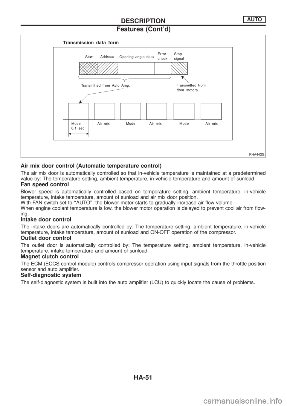
Air mix door control (Automatic temperature control)
The air mix door is automatically controlled so that in-vehicle temperature is maintained at a predetermined
value by: The temperature setting, ambient temperature, in-vehicle temperature and amount of sunload.
Fan speed control
Blower speed is automatically controlled based on temperature setting, ambient temperature, in-vehicle
temperature, intake temperature, amount of sunload and air mix door position.
With FAN switch set to ``AUTO'', the blower motor starts to gradually increase air ¯ow volume.
When engine coolant temperature is low, the blower motor operation is delayed to prevent cool air from ¯ow-
ing.
Intake door control
The intake doors are automatically controlled by: The temperature setting, ambient temperature, in-vehicle
temperature, intake temperature, amount of sunload and ON-OFF operation of the compressor.
Outlet door control
The outlet door is automatically controlled by: The temperature setting, ambient temperature, in-vehicle
temperature, intake temperature and amount of sunload.
Magnet clutch control
The ECM (ECCS control module) controls compressor operation using input signals from the throttle position
sensor and auto ampli®er.
Self-diagnostic system
The self-diagnostic system is built into the auto ampli®er (LCU) to quickly locate the cause of problems.
RHA442G
DESCRIPTIONAUTO
Features (Cont'd)
HA-51
Page 876 of 1226
Component Location
ENGINE COMPARTMENT
RHA697G
TROUBLE DIAGNOSESAUTO
HA-55
Page 884 of 1226
Self-diagnosis
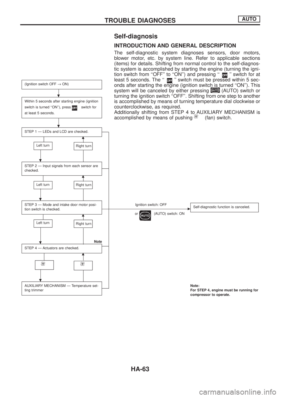
INTRODUCTION AND GENERAL DESCRIPTION
The self-diagnostic system diagnoses sensors, door motors,
blower motor, etc. by system line. Refer to applicable sections
(items) for details. Shifting from normal control to the self-diagnos-
tic system is accomplished by starting the engine (turning the igni-
tion switch from ``OFF'' to ``ON'') and pressing ``
'' switch for at
least 5 seconds. The ``
'' switch must be pressed within 5 sec-
onds after starting the engine (ignition switch is turned ``ON''). This
system will be canceled by either pressing
(AUTO) switch or
turning the ignition switch ``OFF''. Shifting from one step to another
is accomplished by means of turning temperature dial clockwise or
counterclockwise, as required.
Additionally shifting from STEP 4 to AUXILIARY MECHANISM is
accomplished by means of pushing
(fan) switch.
(Ignition switch OFF®ON)
Within 5 seconds after starting engine (ignition
switch is turned ``ON''), press
switch for
at least 5 seconds.
STEP 1 Ð LEDs and LCD are checked.
m
Left turnRight turn
STEP 2 Ð Input signals from each sensor are
checked.
m
Left turnRight turn
STEP 3 Ð Mode and intake door motor posi-
tion switch is checked.Ignition switch: OFFc
or(AUTO) switch: ONSelf-diagnostic function is canceled.m
Left turnRight turn
Note
STEP 4 Ð Actuators are checked.
m
AUXILIARY MECHANISM Ð Temperature set-
ting trimmerNote:
For STEP 4, engine must be running for
compressor to operate.
.
.
.
.
.
.
TROUBLE DIAGNOSESAUTO
HA-63
Page 885 of 1226
STEP-BY-STEP PROCEDURE
Turn ignition switch ON.
Set in self-diagnostic mode. Within 5 sec-
onds after starting engine (ignition switch is
turned ``ON''.), press
switch for at
least 5 seconds.
STEP 1 - LEDs AND LCD ARE CHECKED.
Do all LEDs and LCD illuminate?
Ye s
cNo
Malfunctioning
switch, LED or LCD.
Replace A/C auto amp.
Turn temperature dial clockwise.
Advance to self-diagnosis STEP 2?
Ye s
cNo
Malfunctioning temperature
dial.
Replace A/C auto amp.
Turn temperature dial counterclockwise.
Return to self-diagnosis STEP 1?
Ye s
cNo
Malfunctioning temperature
dial.
Replace A/C auto amp.
Turn temperature dial clockwise.
jA
(Go to next page.)
RHA526G
RHA527G
.
.
.
.
.
.
.
.
TROUBLE DIAGNOSESAUTO
Self-diagnosis (Cont'd)
HA-64
Page 888 of 1226
jC
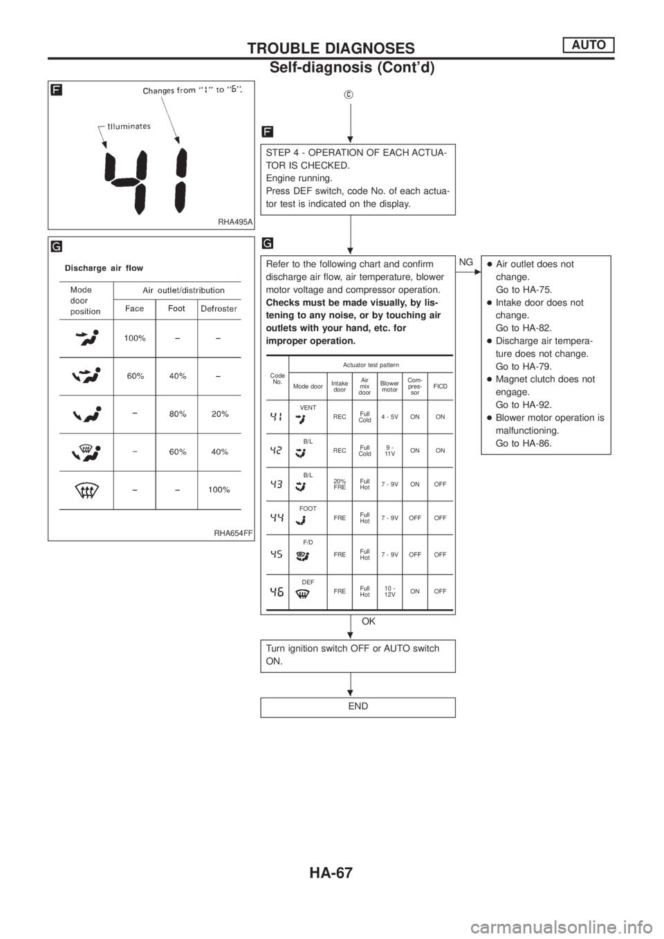
STEP 4 - OPERATION OF EACH ACTUA-
TOR IS CHECKED.
Engine running.
Press DEF switch, code No. of each actua-
tor test is indicated on the display.
Refer to the following chart and con®rm
discharge air ¯ow, air temperature, blower
motor voltage and compressor operation.
Checks must be made visually, by lis-
tening to any noise, or by touching air
outlets with your hand, etc. for
improper operation.
OK
cNG
+Air outlet does not
change.
Go to HA-75.
+Intake door does not
change.
Go to HA-82.
+Discharge air tempera-
ture does not change.
Go to HA-79.
+Magnet clutch does not
engage.
Go to HA-92.
+Blower motor operation is
malfunctioning.
Go to HA-86.
Turn ignition switch OFF or AUTO switch
ON.
END
Code
No.Actuator test pattern
Mode doorIntake
doorAir
mix
doorBlower
motorCom-
pres-
sorFICD
VENTRECFull
Cold4-5V ON ON
B/LRECFull
Cold9-
11 VON ON
B/L20%
FREFull
Hot7-9V ON OFF
FOOTFREFull
Hot7 - 9V OFF OFF
F/D
FREFull
Hot7 - 9V OFF OFF
DEFFREFull
Hot10 -
12VON OFF
RHA495A
RHA654FF
.
.
.
.
TROUBLE DIAGNOSESAUTO
Self-diagnosis (Cont'd)
HA-67
Page 891 of 1226
Operational Check
The purpose of the operational check is to con®rm that the system
operates properly.
CONDITIONS
+Engine running and at normal operating temperature.
PROCEDURE
1. Check memory function
a. Set the temperature 25ÉC.
b. Press OFF switch.
c. Turn the ignition off.
d. Turn the ignition on.
e. Press the AUTO switch.
f. Con®rm that the set temperature remains at previous tempera-
ture.
g. Press OFF switch.
2. Check blower
a. Press fan switch one time.
Blower should operate on low speed.
The fan symbol should have one blade lit
.
b. Press fan switch one more time, and continue checking blower
speed and fan symbol until all speeds are checked.
c. Leave blower on MAX speed
.
3. Check discharge air
a. Press mode switch four times and DEF button.
RHA517G
RHA518G
RHA519G
RHA520G
TROUBLE DIAGNOSESAUTO
HA-70
Page 908 of 1226
SYSTEM DESCRIPTION
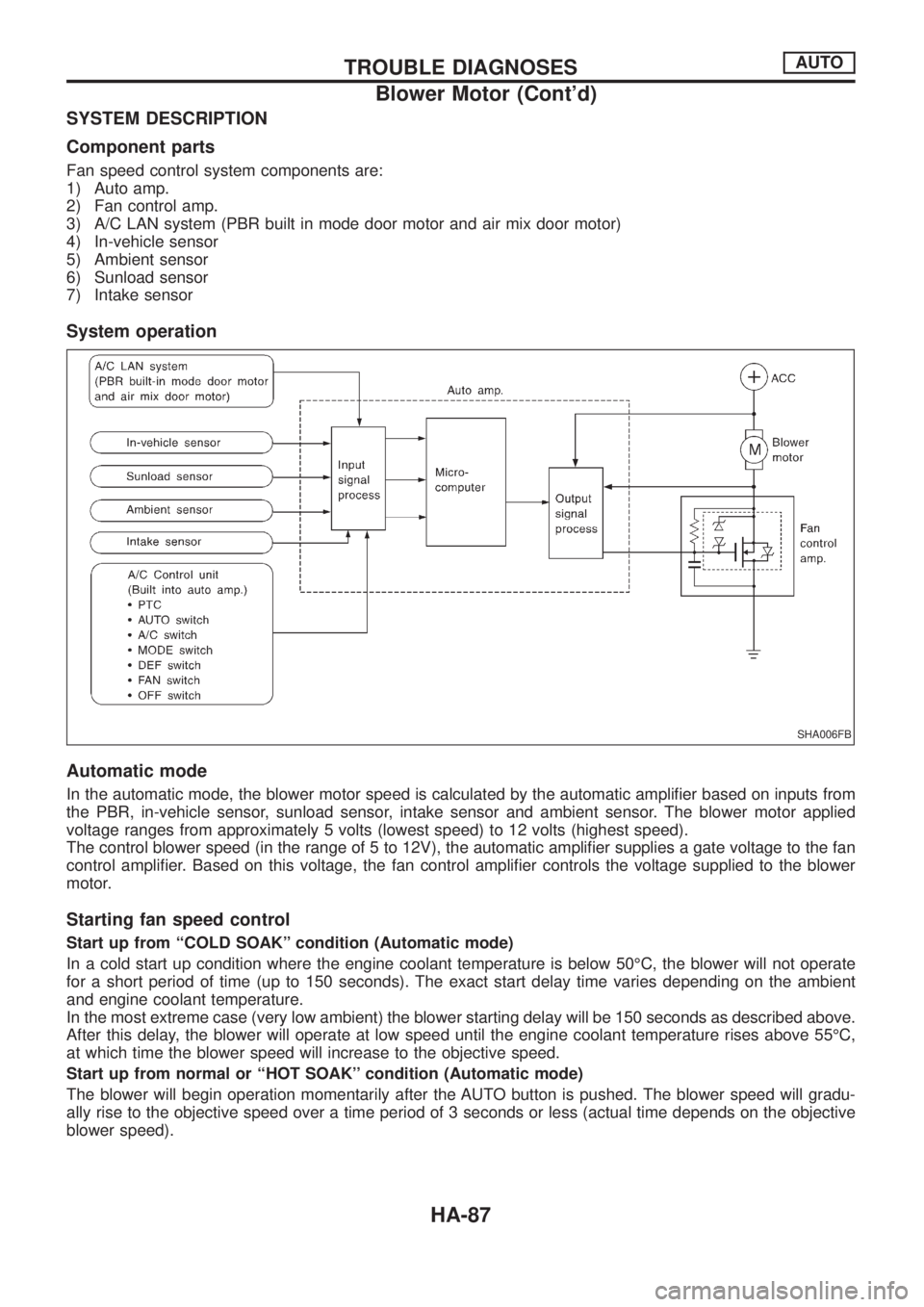
Component parts
Fan speed control system components are:
1) Auto amp.
2) Fan control amp.
3) A/C LAN system (PBR built in mode door motor and air mix door motor)
4) In-vehicle sensor
5) Ambient sensor
6) Sunload sensor
7) Intake sensor
System operation
Automatic mode
In the automatic mode, the blower motor speed is calculated by the automatic ampli®er based on inputs from
the PBR, in-vehicle sensor, sunload sensor, intake sensor and ambient sensor. The blower motor applied
voltage ranges from approximately 5 volts (lowest speed) to 12 volts (highest speed).
The control blower speed (in the range of 5 to 12V), the automatic ampli®er supplies a gate voltage to the fan
control ampli®er. Based on this voltage, the fan control ampli®er controls the voltage supplied to the blower
motor.
Starting fan speed control
Start up from ``COLD SOAK'' condition (Automatic mode)
In a cold start up condition where the engine coolant temperature is below 50ÉC, the blower will not operate
for a short period of time (up to 150 seconds). The exact start delay time varies depending on the ambient
and engine coolant temperature.
In the most extreme case (very low ambient) the blower starting delay will be 150 seconds as described above.
After this delay, the blower will operate at low speed until the engine coolant temperature rises above 55ÉC,
at which time the blower speed will increase to the objective speed.
Start up from normal or ``HOT SOAK'' condition (Automatic mode)
The blower will begin operation momentarily after the AUTO button is pushed. The blower speed will gradu-
ally rise to the objective speed over a time period of 3 seconds or less (actual time depends on the objective
blower speed).
SHA006FB
TROUBLE DIAGNOSESAUTO
Blower Motor (Cont'd)
HA-87
Page 915 of 1226
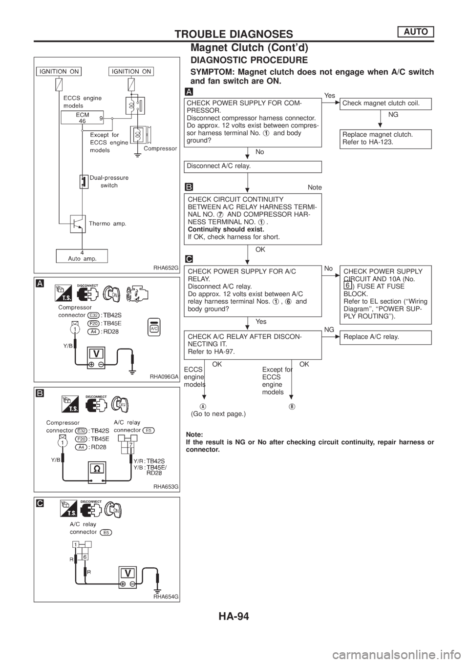
DIAGNOSTIC PROCEDURE
SYMPTOM: Magnet clutch does not engage when A/C switch
and fan switch are ON.
CHECK POWER SUPPLY FOR COM-
PRESSOR.
Disconnect compressor harness connector.
Do approx. 12 volts exist between compres-
sor harness terminal No.j
1and body
ground?
No
cYe s
Check magnet clutch coil.
NG
Replace magnet clutch.
Refer to HA-123.
Disconnect A/C relay.
Note
CHECK CIRCUIT CONTINUITY
BETWEEN A/C RELAY HARNESS TERMI-
NAL NO.j
7AND COMPRESSOR HAR-
NESS TERMINAL NO.j1.
Continuity should exist.
If OK, check harness for short.
OK
CHECK POWER SUPPLY FOR A/C
RELAY.
Disconnect A/C relay.
Do approx. 12 volts exist between A/C
relay harness terminal Nos.j
1,j6and
body ground?
Ye s
cNo
CHECK POWER SUPPLY
CIRCUIT AND 10A (No.
) FUSE AT FUSE
BLOCK.
Refer to EL section (``Wiring
Diagram'', ``POWER SUP-
PLY ROUTING'').
CHECK A/C RELAY AFTER DISCON-
NECTING IT.
Refer to HA-97.
OK OK
ECCS
engine
modelsExcept for
ECCS
engine
models
cNG
Replace A/C relay.
jA(Go to next page.)jB
Note:
If the result is NG or No after checking circuit continuity, repair harness or
connector.
RHA652G
RHA096GA
RHA653G
RHA654G
.
.
.
.
.
..
TROUBLE DIAGNOSESAUTO
Magnet Clutch (Cont'd)
HA-94