Page 816 of 1226
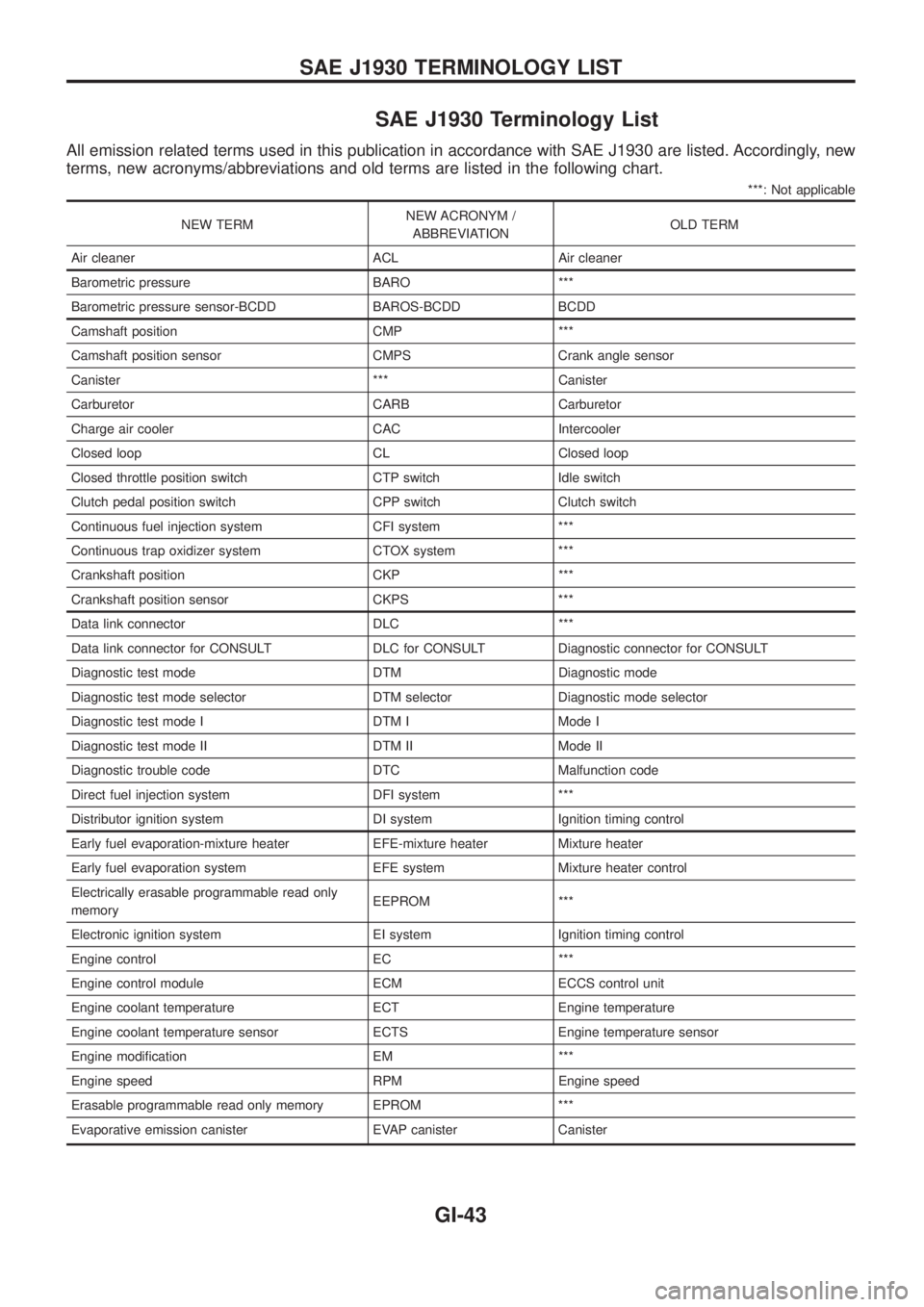
SAE J1930 Terminology List
All emission related terms used in this publication in accordance with SAE J1930 are listed. Accordingly, new
terms, new acronyms/abbreviations and old terms are listed in the following chart.
***: Not applicable
NEW TERMNEW ACRONYM /
ABBREVIATIONOLD TERM
Air cleaner ACL Air cleaner
Barometric pressure BARO ***
Barometric pressure sensor-BCDD BAROS-BCDD BCDD
Camshaft position CMP ***
Camshaft position sensor CMPS Crank angle sensor
Canister *** Canister
Carburetor CARB Carburetor
Charge air cooler CAC Intercooler
Closed loop CL Closed loop
Closed throttle position switch CTP switch Idle switch
Clutch pedal position switch CPP switch Clutch switch
Continuous fuel injection system CFI system ***
Continuous trap oxidizer system CTOX system ***
Crankshaft position CKP ***
Crankshaft position sensor CKPS ***
Data link connector DLC ***
Data link connector for CONSULT DLC for CONSULT Diagnostic connector for CONSULT
Diagnostic test mode DTM Diagnostic mode
Diagnostic test mode selector DTM selector Diagnostic mode selector
Diagnostic test mode I DTM I Mode I
Diagnostic test mode II DTM II Mode II
Diagnostic trouble code DTC Malfunction code
Direct fuel injection system DFI system ***
Distributor ignition system DI system Ignition timing control
Early fuel evaporation-mixture heater EFE-mixture heater Mixture heater
Early fuel evaporation system EFE system Mixture heater control
Electrically erasable programmable read only
memoryEEPROM ***
Electronic ignition system EI system Ignition timing control
Engine control EC ***
Engine control module ECM ECCS control unit
Engine coolant temperature ECT Engine temperature
Engine coolant temperature sensor ECTS Engine temperature sensor
Engine modi®cation EM ***
Engine speed RPM Engine speed
Erasable programmable read only memory EPROM ***
Evaporative emission canister EVAP canister Canister
SAE J1930 TERMINOLOGY LIST
GI-43
Page 817 of 1226
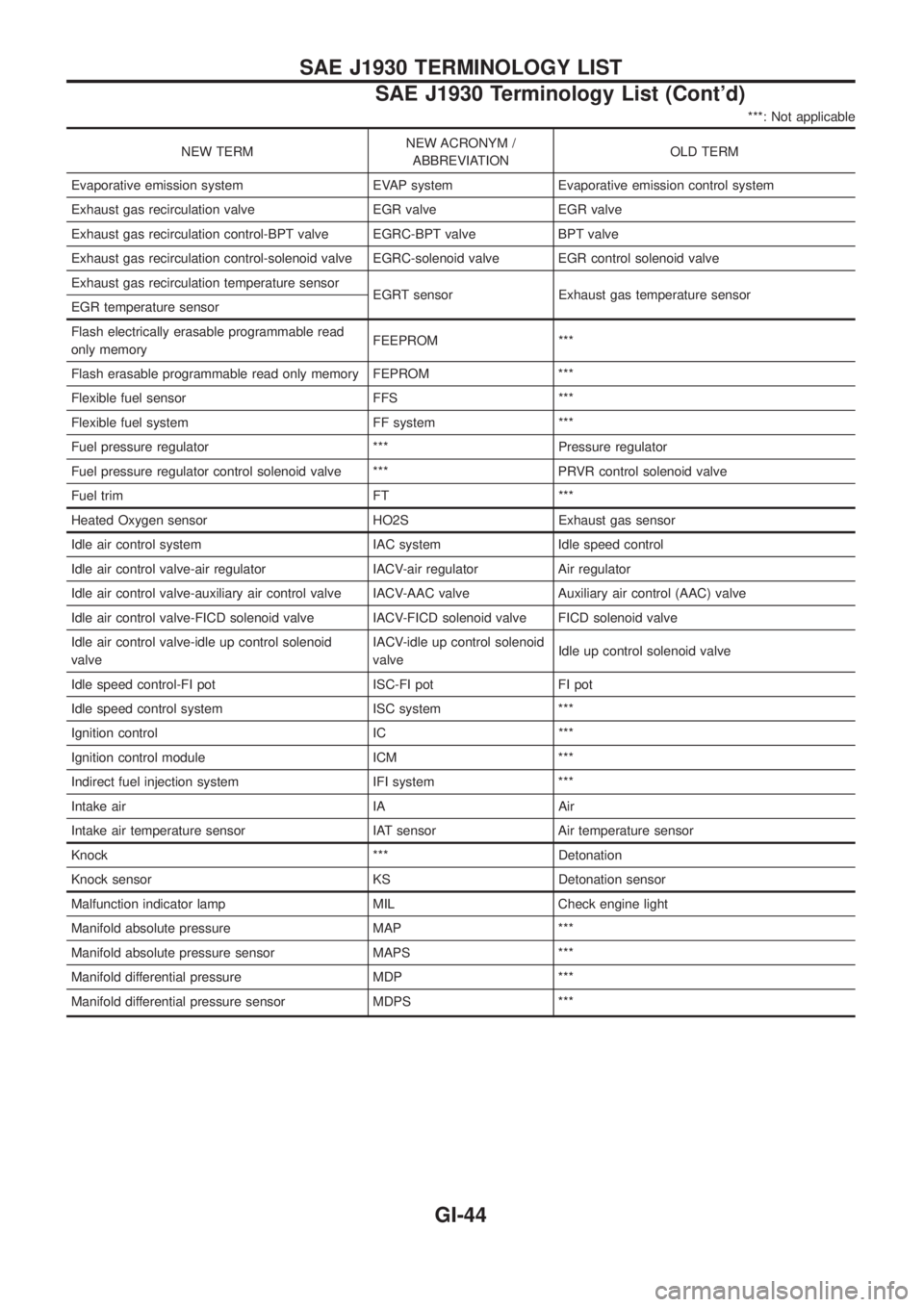
***: Not applicable
NEW TERMNEW ACRONYM /
ABBREVIATIONOLD TERM
Evaporative emission system EVAP system Evaporative emission control system
Exhaust gas recirculation valve EGR valve EGR valve
Exhaust gas recirculation control-BPT valve EGRC-BPT valve BPT valve
Exhaust gas recirculation control-solenoid valve EGRC-solenoid valve EGR control solenoid valve
Exhaust gas recirculation temperature sensor
EGRT sensor Exhaust gas temperature sensor
EGR temperature sensor
Flash electrically erasable programmable read
only memoryFEEPROM ***
Flash erasable programmable read only memory FEPROM ***
Flexible fuel sensor FFS ***
Flexible fuel system FF system ***
Fuel pressure regulator *** Pressure regulator
Fuel pressure regulator control solenoid valve *** PRVR control solenoid valve
Fuel trim FT ***
Heated Oxygen sensor HO2S Exhaust gas sensor
Idle air control system IAC system Idle speed control
Idle air control valve-air regulator IACV-air regulator Air regulator
Idle air control valve-auxiliary air control valve IACV-AAC valve Auxiliary air control (AAC) valve
Idle air control valve-FICD solenoid valve IACV-FICD solenoid valve FICD solenoid valve
Idle air control valve-idle up control solenoid
valveIACV-idle up control solenoid
valveIdle up control solenoid valve
Idle speed control-FI pot ISC-FI pot FI pot
Idle speed control system ISC system ***
Ignition control IC ***
Ignition control module ICM ***
Indirect fuel injection system IFI system ***
Intake air IA Air
Intake air temperature sensor IAT sensor Air temperature sensor
Knock *** Detonation
Knock sensor KS Detonation sensor
Malfunction indicator lamp MIL Check engine light
Manifold absolute pressure MAP ***
Manifold absolute pressure sensor MAPS ***
Manifold differential pressure MDP ***
Manifold differential pressure sensor MDPS ***
SAE J1930 TERMINOLOGY LIST
SAE J1930 Terminology List (Cont'd)
GI-44
Page 827 of 1226
Precautions for Servicing Compressor
+Plug all openings to prevent moisture and foreign matter from entering.
+When the compressor is removed, store it in the same position as it is when mounted on the car.
+When replacing or repairing compressor, follow ``Maintenance of Lubricant Quantity in Compres-
sor'' exactly. Refer to HA-114.
+Keep friction surfaces between clutch and pulley clean. If the surface is contaminated, with
lubricant, wipe it off by using a clean waste cloth moistened with thinner.
+After compressor service operation, turn the compressor shaft by hand more than ®ve turns in
both directions. This will equally distribute lubricant inside the compressor. After the compressor
is installed, let the engine idle and operate the compressor for one hour.
+After replacing the compressor magnet clutch, apply voltage to the new one and check for normal
operation.
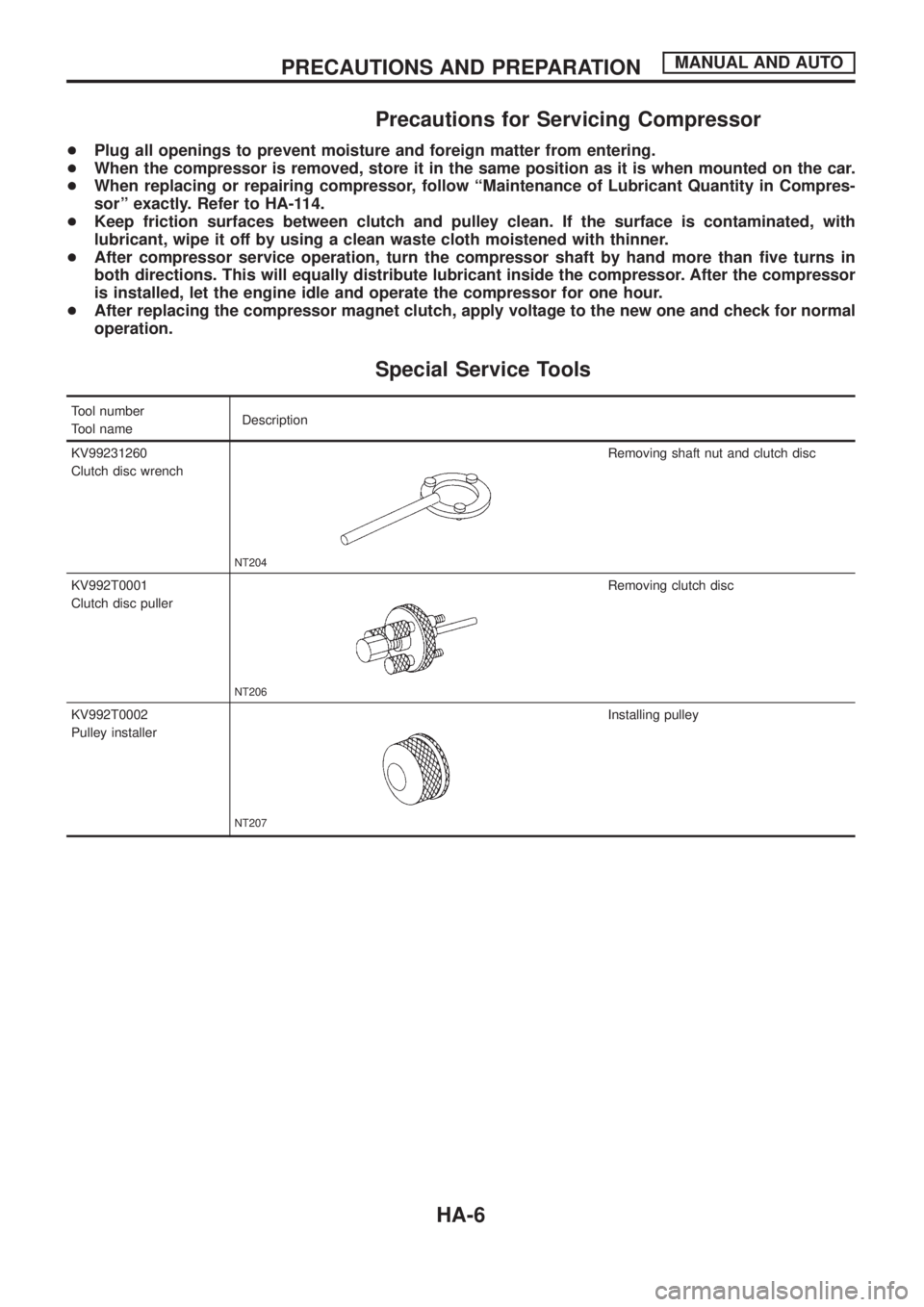
Special Service Tools
Tool number
Tool nameDescription
KV99231260
Clutch disc wrench
NT204
Removing shaft nut and clutch disc
KV992T0001
Clutch disc puller
NT206
Removing clutch disc
KV992T0002
Pulley installer
NT207
Installing pulley
PRECAUTIONS AND PREPARATIONMANUAL AND AUTO
HA-6
Page 837 of 1226
System Description
SWITCH AND THEIR CONTROL FUNCTIONS
Knob/SwitchKnob/Switch position
Air outlet Intake air Compressor
A/C
A/CjÐ Ð ON*
Mode
jVENT Ð Ð
jB/L Ð Ð
jFOOT Ð Ð
jD/F FRE Ð
jDEF FRE ON*
jÐÐÐ
*: Compressor is operated by dual-pressure switch.
Control Operation
FAN CONTROL KNOB
This knob turns the fan ON and OFF, and controls fan speed.
MODE CONTROL KNOB
This knob controls the outlet air ¯ow.
TEMPERATURE CONTROL KNOB
This knob allows adjustment of the temperature of the outlet air.
RECIRCULATION (REC) SWITCH
OFF position: Outside air is drawn into the passenger compartment.
ON position: Interior air is recirculated inside the vehicle. The indicator lamp will also light.
AIR CONDITIONER SWITCH
The air conditioner switch controls the A/C system. When the switch is depressed with the fan ON, the com-
pressor will turn ON. The indicator lamp will also light.
The air conditioner cooling function operates only when the engine is running.
RHA582G
DESCRIPTIONMANUAL
HA-16
Page 838 of 1226
Component Location
ENGINE COMPARTMENT
RHA641G
TROUBLE DIAGNOSESMANUAL
HA-17
Page 843 of 1226
Operational Check
The purpose of the operational check is to con®rm that the system
operates properly.
CONDITIONS
Engine running at normal operating temperature.
PROCEDURE
1. Check blower
a. Turn fan control knob to 1-speed.
Blower should operate on 1-speed.
b. Then turn fan control knob to 2-speed.
c. Continue checking blower speed until all four speeds are
checked.
d. Leave blower on 4-speed.
2. Check discharge air
a. Turn mode control knob.
b. Con®rm that discharge air comes out according to the air dis-
tribution table at left.
Refer to ``Discharge Air Flow'' in ``DESCRIPTION'' (HA-13).
RHA583G
RHA584G
RHA654F
TROUBLE DIAGNOSESMANUAL
HA-22
Page 856 of 1226
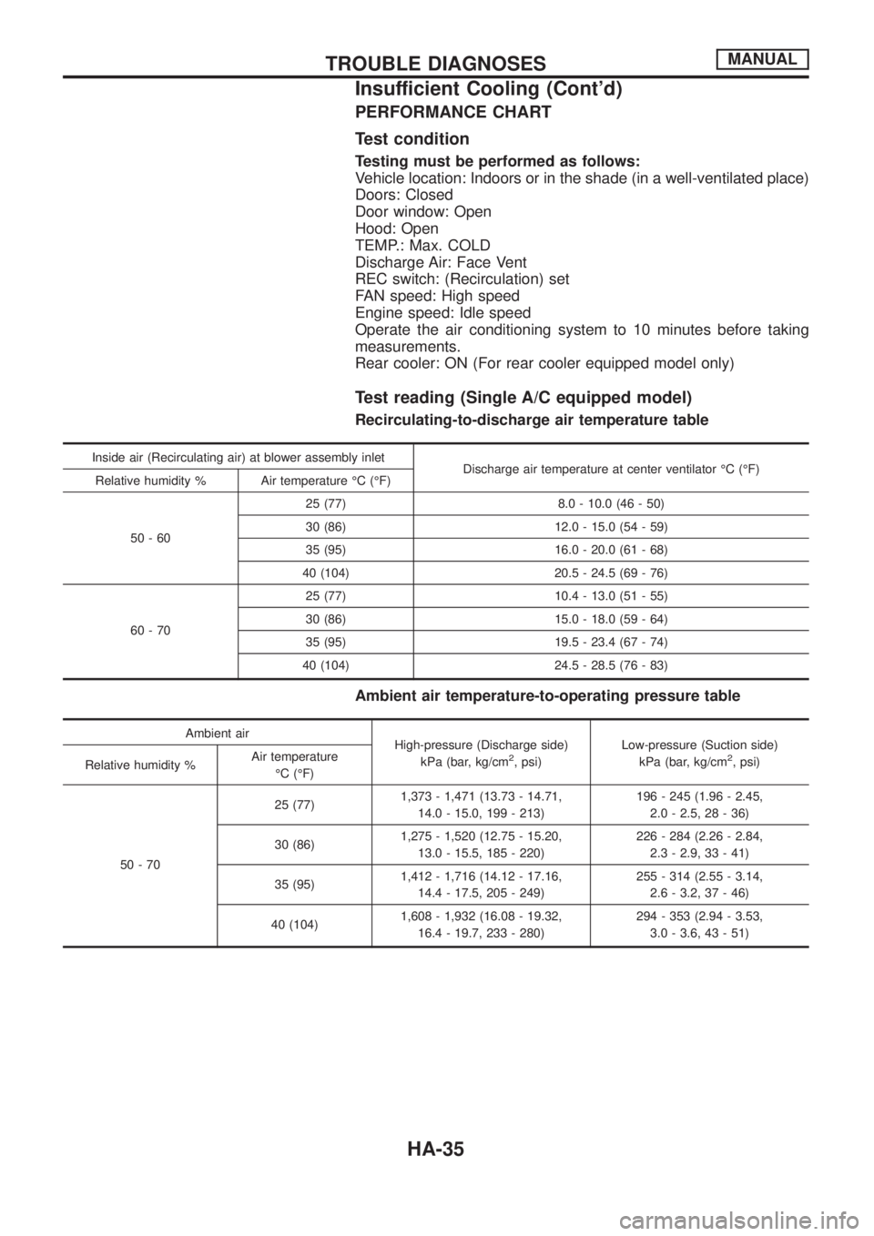
PERFORMANCE CHART
Test condition
Testing must be performed as follows:
Vehicle location: Indoors or in the shade (in a well-ventilated place)
Doors: Closed
Door window: Open
Hood: Open
TEMP.: Max. COLD
Discharge Air: Face Vent
REC switch: (Recirculation) set
FAN speed: High speed
Engine speed: Idle speed
Operate the air conditioning system to 10 minutes before taking
measurements.
Rear cooler: ON (For rear cooler equipped model only)
Test reading (Single A/C equipped model)
Recirculating-to-discharge air temperature table
Inside air (Recirculating air) at blower assembly inlet
Discharge air temperature at center ventilator ÉC (ÉF)
Relative humidity % Air temperature ÉC (ÉF)
50-6025 (77) 8.0 - 10.0 (46 - 50)
30 (86) 12.0 - 15.0 (54 - 59)
35 (95) 16.0 - 20.0 (61 - 68)
40 (104) 20.5 - 24.5 (69 - 76)
60-7025 (77) 10.4 - 13.0 (51 - 55)
30 (86) 15.0 - 18.0 (59 - 64)
35 (95) 19.5 - 23.4 (67 - 74)
40 (104) 24.5 - 28.5 (76 - 83)
Ambient air temperature-to-operating pressure table
Ambient air
High-pressure (Discharge side)
kPa (bar, kg/cm
2, psi)Low-pressure (Suction side)
kPa (bar, kg/cm2, psi)
Relative humidity %Air temperature
ÉC (ÉF)
50-7025 (77)1,373 - 1,471 (13.73 - 14.71,
14.0 - 15.0, 199 - 213)196 - 245 (1.96 - 2.45,
2.0 - 2.5, 28 - 36)
30 (86)1,275 - 1,520 (12.75 - 15.20,
13.0 - 15.5, 185 - 220)226 - 284 (2.26 - 2.84,
2.3 - 2.9, 33 - 41)
35 (95)1,412 - 1,716 (14.12 - 17.16,
14.4 - 17.5, 205 - 249)255 - 314 (2.55 - 3.14,
2.6 - 3.2, 37 - 46)
40 (104)1,608 - 1,932 (16.08 - 19.32,
16.4 - 19.7, 233 - 280)294 - 353 (2.94 - 3.53,
3.0 - 3.6, 43 - 51)
TROUBLE DIAGNOSESMANUAL
Insufficient Cooling (Cont'd)
HA-35
Page 857 of 1226
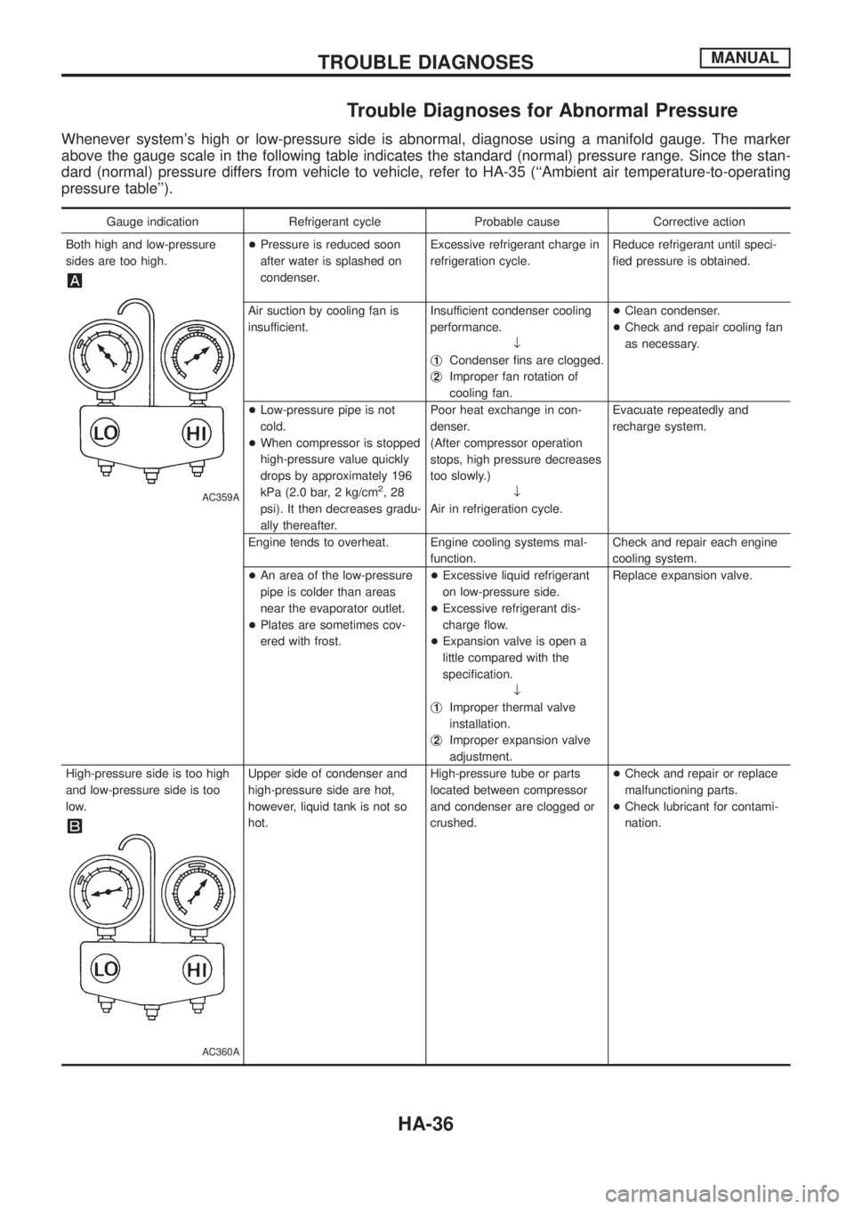
Trouble Diagnoses for Abnormal Pressure
Whenever system's high or low-pressure side is abnormal, diagnose using a manifold gauge. The marker
above the gauge scale in the following table indicates the standard (normal) pressure range. Since the stan-
dard (normal) pressure differs from vehicle to vehicle, refer to HA-35 (``Ambient air temperature-to-operating
pressure table'').
Gauge indication Refrigerant cycle Probable cause Corrective action
Both high and low-pressure
sides are too high.
AC359A
+Pressure is reduced soon
after water is splashed on
condenser.Excessive refrigerant charge in
refrigeration cycle.Reduce refrigerant until speci-
®ed pressure is obtained.
Air suction by cooling fan is
insufficient.Insufficient condenser cooling
performance.
¯
j
1Condenser ®ns are clogged.
j
2Improper fan rotation of
cooling fan.+Clean condenser.
+Check and repair cooling fan
as necessary.
+Low-pressure pipe is not
cold.
+When compressor is stopped
high-pressure value quickly
drops by approximately 196
kPa (2.0 bar, 2 kg/cm
2,28
psi). It then decreases gradu-
ally thereafter.Poor heat exchange in con-
denser.
(After compressor operation
stops, high pressure decreases
too slowly.)
¯
Air in refrigeration cycle.Evacuate repeatedly and
recharge system.
Engine tends to overheat. Engine cooling systems mal-
function.Check and repair each engine
cooling system.
+An area of the low-pressure
pipe is colder than areas
near the evaporator outlet.
+Plates are sometimes cov-
ered with frost.+Excessive liquid refrigerant
on low-pressure side.
+Excessive refrigerant dis-
charge ¯ow.
+Expansion valve is open a
little compared with the
speci®cation.
¯
j
1Improper thermal valve
installation.
j
2Improper expansion valve
adjustment.Replace expansion valve.
High-pressure side is too high
and low-pressure side is too
low.
AC360A
Upper side of condenser and
high-pressure side are hot,
however, liquid tank is not so
hot.High-pressure tube or parts
located between compressor
and condenser are clogged or
crushed.+Check and repair or replace
malfunctioning parts.
+Check lubricant for contami-
nation.
TROUBLE DIAGNOSESMANUAL
HA-36