2006 NISSAN PATROL transmission
[x] Cancel search: transmissionPage 819 of 1226
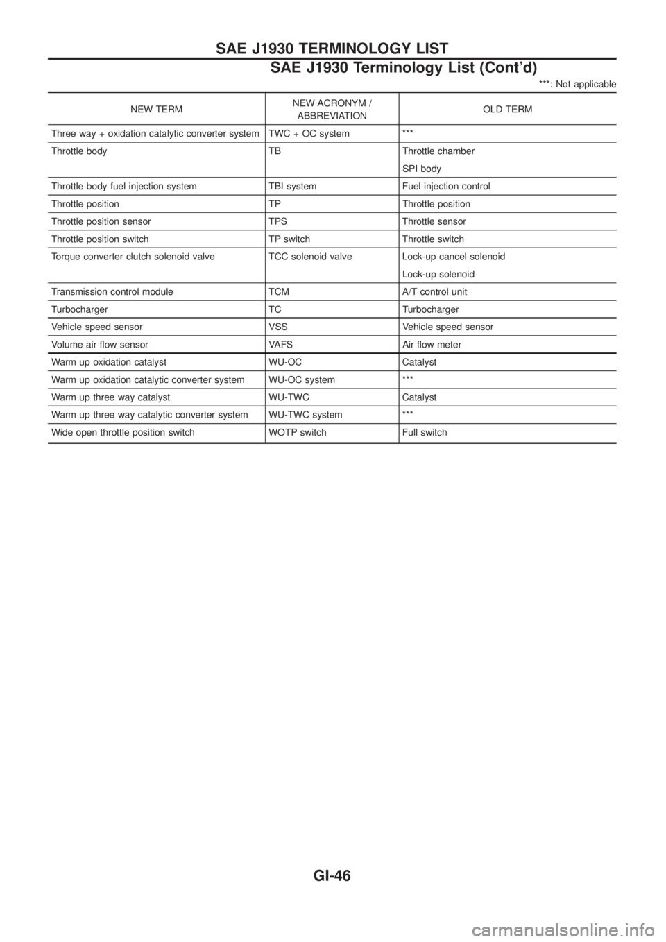
***: Not applicable
NEW TERMNEW ACRONYM /
ABBREVIATIONOLD TERM
Three way + oxidation catalytic converter system TWC + OC system ***
Throttle body TB Throttle chamber
SPI body
Throttle body fuel injection system TBI system Fuel injection control
Throttle position TP Throttle position
Throttle position sensor TPS Throttle sensor
Throttle position switch TP switch Throttle switch
Torque converter clutch solenoid valve TCC solenoid valve Lock-up cancel solenoid
Lock-up solenoid
Transmission control module TCM A/T control unit
Turbocharger TC Turbocharger
Vehicle speed sensor VSS Vehicle speed sensor
Volume air ¯ow sensor VAFS Air ¯ow meter
Warm up oxidation catalyst WU-OC Catalyst
Warm up oxidation catalytic converter system WU-OC system ***
Warm up three way catalyst WU-TWC Catalyst
Warm up three way catalytic converter system WU-TWC system ***
Wide open throttle position switch WOTP switch Full switch
SAE J1930 TERMINOLOGY LIST
SAE J1930 Terminology List (Cont'd)
GI-46
Page 870 of 1226
Introduction
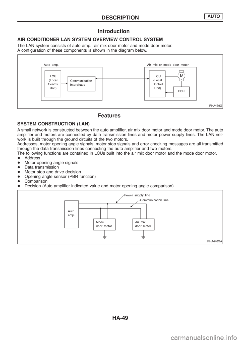
AIR CONDITIONER LAN SYSTEM OVERVIEW CONTROL SYSTEM
The LAN system consists of auto amp., air mix door motor and mode door motor.
A con®guration of these components is shown in the diagram below.
Features
SYSTEM CONSTRUCTION (LAN)
A small network is constructed between the auto ampli®er, air mix door motor and mode door motor. The auto
ampli®er and motors are connected by data transmission lines and motor power supply lines. The LAN net-
work is built through the ground circuits of the two motors.
Addresses, motor opening angle signals, motor stop signals and error checking messages are all transmitted
through the data transmission lines connecting the auto ampli®er and two motors.
The following functions are contained in LCUs built into the air mix door motor and the mode door motor.
+Address
+Motor opening angle signals
+Data transmission
+Motor stop and drive decision
+Opening angle sensor (PBR function)
+Comparison
+Decision (Auto ampli®er indicated value and motor opening angle comparison)
RHA439G
RHA440GA
DESCRIPTIONAUTO
HA-49
Page 871 of 1226
Operation
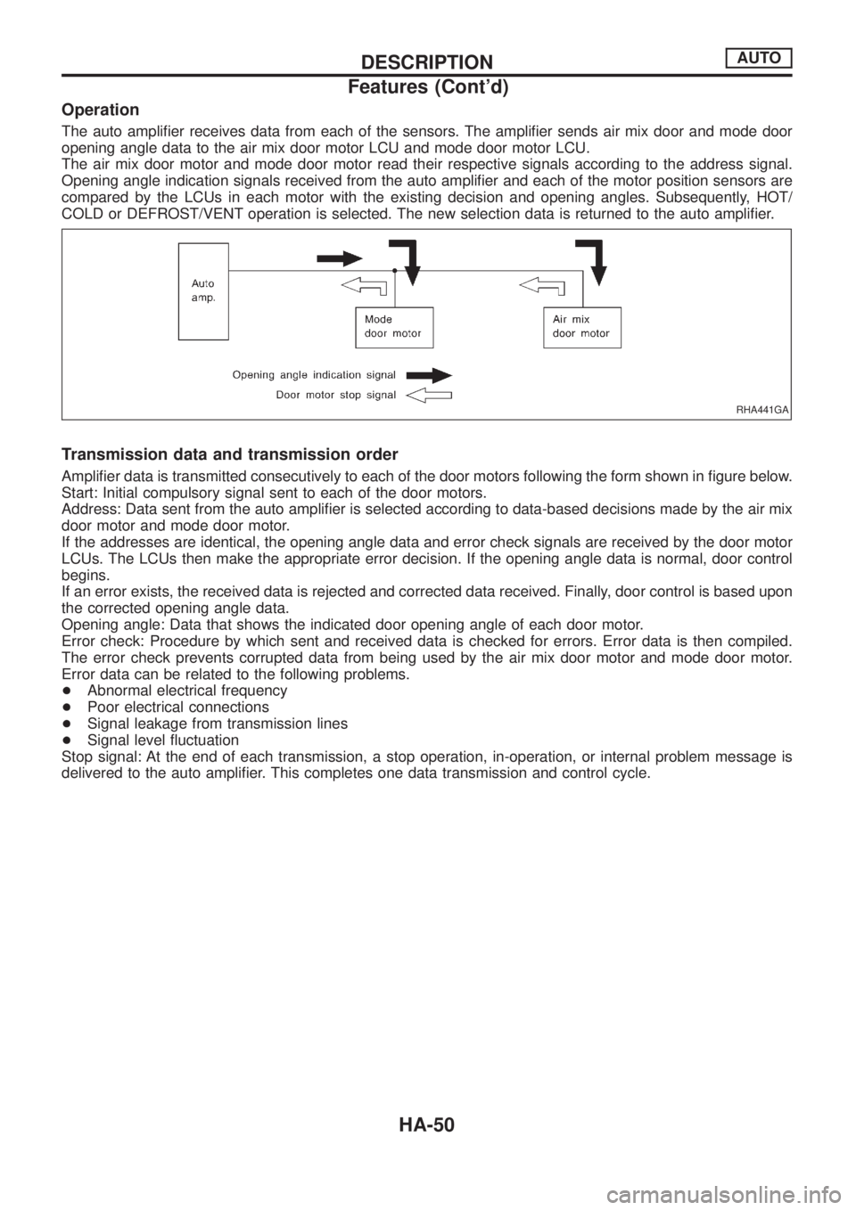
The auto ampli®er receives data from each of the sensors. The ampli®er sends air mix door and mode door
opening angle data to the air mix door motor LCU and mode door motor LCU.
The air mix door motor and mode door motor read their respective signals according to the address signal.
Opening angle indication signals received from the auto ampli®er and each of the motor position sensors are
compared by the LCUs in each motor with the existing decision and opening angles. Subsequently, HOT/
COLD or DEFROST/VENT operation is selected. The new selection data is returned to the auto ampli®er.
Transmission data and transmission order
Ampli®er data is transmitted consecutively to each of the door motors following the form shown in ®gure below.
Start: Initial compulsory signal sent to each of the door motors.
Address: Data sent from the auto ampli®er is selected according to data-based decisions made by the air mix
door motor and mode door motor.
If the addresses are identical, the opening angle data and error check signals are received by the door motor
LCUs. The LCUs then make the appropriate error decision. If the opening angle data is normal, door control
begins.
If an error exists, the received data is rejected and corrected data received. Finally, door control is based upon
the corrected opening angle data.
Opening angle: Data that shows the indicated door opening angle of each door motor.
Error check: Procedure by which sent and received data is checked for errors. Error data is then compiled.
The error check prevents corrupted data from being used by the air mix door motor and mode door motor.
Error data can be related to the following problems.
+Abnormal electrical frequency
+Poor electrical connections
+Signal leakage from transmission lines
+Signal level ¯uctuation
Stop signal: At the end of each transmission, a stop operation, in-operation, or internal problem message is
delivered to the auto ampli®er. This completes one data transmission and control cycle.
RHA441GA
DESCRIPTIONAUTO
Features (Cont'd)
HA-50
Page 952 of 1226
M
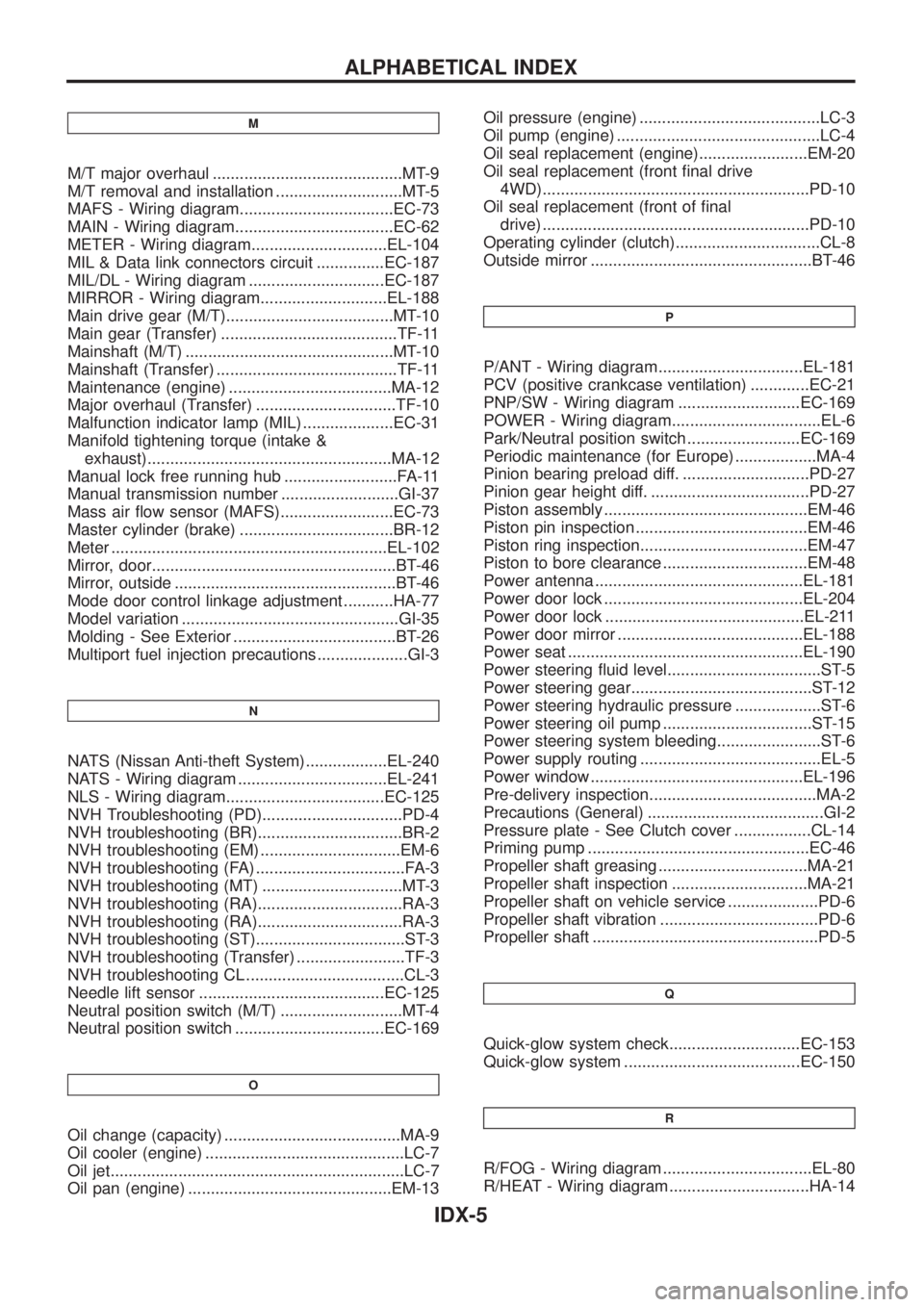
M/T major overhaul ..........................................MT-9
M/T removal and installation ............................MT-5
MAFS - Wiring diagram..................................EC-73
MAIN - Wiring diagram...................................EC-62
METER - Wiring diagram..............................EL-104
MIL & Data link connectors circuit ...............EC-187
MIL/DL - Wiring diagram ..............................EC-187
MIRROR - Wiring diagram............................EL-188
Main drive gear (M/T).....................................MT-10
Main gear (Transfer) .......................................TF-11
Mainshaft (M/T) ..............................................MT-10
Mainshaft (Transfer) ........................................TF-11
Maintenance (engine) ....................................MA-12
Major overhaul (Transfer) ...............................TF-10
Malfunction indicator lamp (MIL) ....................EC-31
Manifold tightening torque (intake &
exhaust)......................................................MA-12
Manual lock free running hub .........................FA-11
Manual transmission number ..........................GI-37
Mass air ¯ow sensor (MAFS).........................EC-73
Master cylinder (brake) ..................................BR-12
Meter .............................................................EL-102
Mirror, door......................................................BT-46
Mirror, outside .................................................BT-46
Mode door control linkage adjustment ...........HA-77
Model variation ................................................GI-35
Molding - See Exterior ....................................BT-26
Multiport fuel injection precautions ....................GI-3
N
NATS (Nissan Anti-theft System)..................EL-240
NATS - Wiring diagram .................................EL-241
NLS - Wiring diagram...................................EC-125
NVH Troubleshooting (PD)...............................PD-4
NVH troubleshooting (BR)................................BR-2
NVH troubleshooting (EM) ...............................EM-6
NVH troubleshooting (FA) .................................FA-3
NVH troubleshooting (MT) ...............................MT-3
NVH troubleshooting (RA)................................RA-3
NVH troubleshooting (RA)................................RA-3
NVH troubleshooting (ST).................................ST-3
NVH troubleshooting (Transfer) ........................TF-3
NVH troubleshooting CL ...................................CL-3
Needle lift sensor .........................................EC-125
Neutral position switch (M/T) ...........................MT-4
Neutral position switch .................................EC-169
O
Oil change (capacity) .......................................MA-9
Oil cooler (engine) ............................................LC-7
Oil jet.................................................................LC-7
Oil pan (engine) .............................................EM-13Oil pressure (engine) ........................................LC-3
Oil pump (engine) .............................................LC-4
Oil seal replacement (engine)........................EM-20
Oil seal replacement (front ®nal drive
4WD)...........................................................PD-10
Oil seal replacement (front of ®nal
drive) ...........................................................PD-10
Operating cylinder (clutch)................................CL-8
Outside mirror .................................................BT-46
P
P/ANT - Wiring diagram................................EL-181
PCV (positive crankcase ventilation) .............EC-21
PNP/SW - Wiring diagram ...........................EC-169
POWER - Wiring diagram.................................EL-6
Park/Neutral position switch .........................EC-169
Periodic maintenance (for Europe) ..................MA-4
Pinion bearing preload diff. ............................PD-27
Pinion gear height diff. ...................................PD-27
Piston assembly .............................................EM-46
Piston pin inspection ......................................EM-46
Piston ring inspection.....................................EM-47
Piston to bore clearance ................................EM-48
Power antenna ..............................................EL-181
Power door lock ............................................EL-204
Power door lock ............................................EL-211
Power door mirror .........................................EL-188
Power seat ....................................................EL-190
Power steering ¯uid level..................................ST-5
Power steering gear........................................ST-12
Power steering hydraulic pressure ...................ST-6
Power steering oil pump .................................ST-15
Power steering system bleeding.......................ST-6
Power supply routing ........................................EL-5
Power window ...............................................EL-196
Pre-delivery inspection.....................................MA-2
Precautions (General) .......................................GI-2
Pressure plate - See Clutch cover .................CL-14
Priming pump .................................................EC-46
Propeller shaft greasing .................................MA-21
Propeller shaft inspection ..............................MA-21
Propeller shaft on vehicle service ....................PD-6
Propeller shaft vibration ...................................PD-6
Propeller shaft ..................................................PD-5
Q
Quick-glow system check.............................EC-153
Quick-glow system .......................................EC-150
R
R/FOG - Wiring diagram .................................EL-80
R/HEAT - Wiring diagram ...............................HA-14
ALPHABETICAL INDEX
IDX-5
Page 954 of 1226
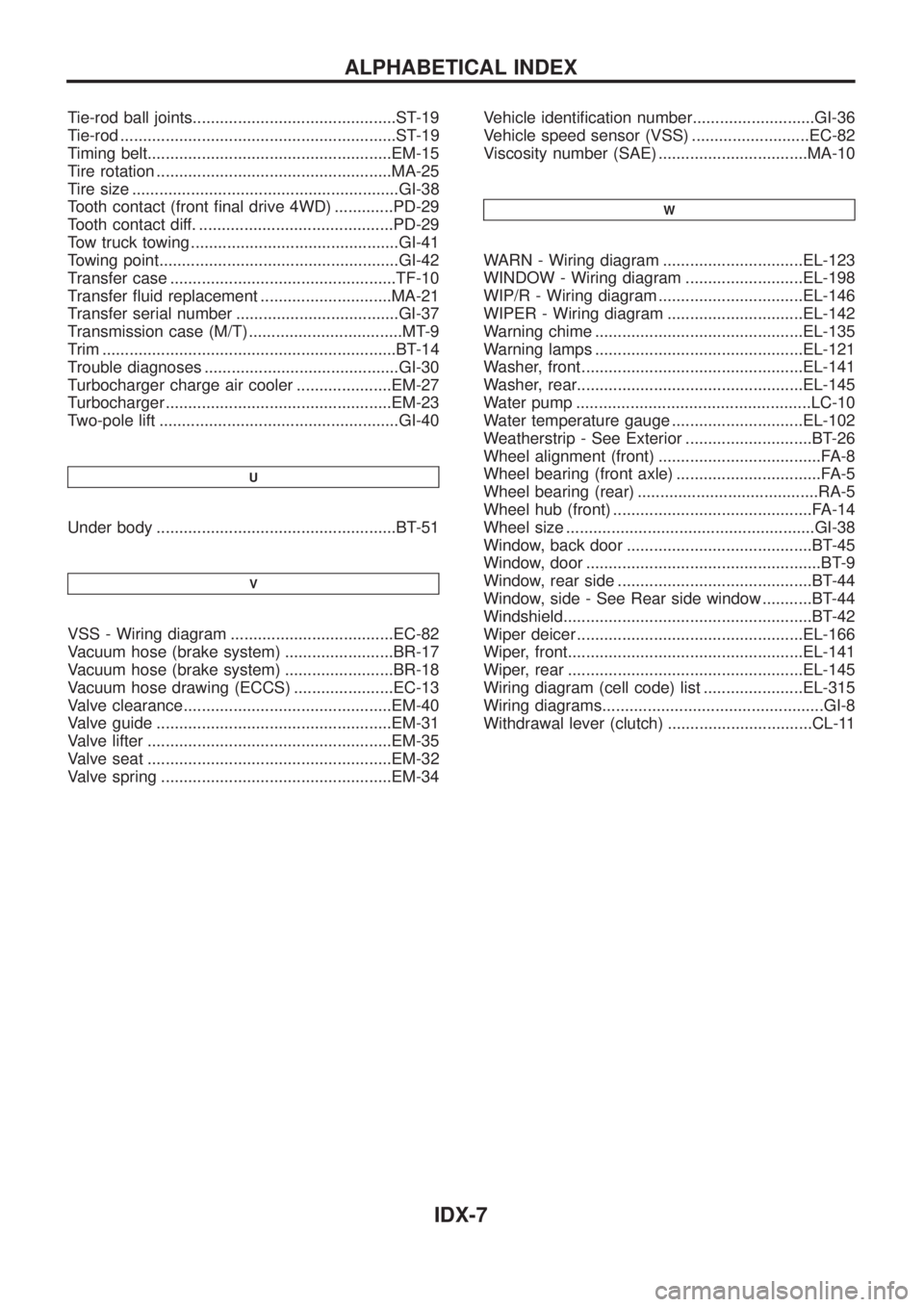
Tie-rod ball joints.............................................ST-19
Tie-rod .............................................................ST-19
Timing belt......................................................EM-15
Tire rotation ....................................................MA-25
Tire size ...........................................................GI-38
Tooth contact (front ®nal drive 4WD) .............PD-29
Tooth contact diff. ...........................................PD-29
Tow truck towing ..............................................GI-41
Towing point.....................................................GI-42
Transfer case ..................................................TF-10
Transfer ¯uid replacement .............................MA-21
Transfer serial number ....................................GI-37
Transmission case (M/T) ..................................MT-9
Trim .................................................................BT-14
Trouble diagnoses ...........................................GI-30
Turbocharger charge air cooler .....................EM-27
Turbocharger ..................................................EM-23
Two-pole lift .....................................................GI-40
U
Under body .....................................................BT-51
V
VSS - Wiring diagram ....................................EC-82
Vacuum hose (brake system) ........................BR-17
Vacuum hose (brake system) ........................BR-18
Vacuum hose drawing (ECCS) ......................EC-13
Valve clearance..............................................EM-40
Valve guide ....................................................EM-31
Valve lifter ......................................................EM-35
Valve seat ......................................................EM-32
Valve spring ...................................................EM-34Vehicle identi®cation number...........................GI-36
Vehicle speed sensor (VSS) ..........................EC-82
Viscosity number (SAE) .................................MA-10
W
WARN - Wiring diagram ...............................EL-123
WINDOW - Wiring diagram ..........................EL-198
WIP/R - Wiring diagram ................................EL-146
WIPER - Wiring diagram ..............................EL-142
Warning chime ..............................................EL-135
Warning lamps ..............................................EL-121
Washer, front .................................................EL-141
Washer, rear..................................................EL-145
Water pump ....................................................LC-10
Water temperature gauge .............................EL-102
Weatherstrip - See Exterior ............................BT-26
Wheel alignment (front) ....................................FA-8
Wheel bearing (front axle) ................................FA-5
Wheel bearing (rear) ........................................RA-5
Wheel hub (front) ............................................FA-14
Wheel size .......................................................GI-38
Window, back door .........................................BT-45
Window, door ....................................................BT-9
Window, rear side ...........................................BT-44
Window, side - See Rear side window ...........BT-44
Windshield.......................................................BT-42
Wiper deicer ..................................................EL-166
Wiper, front....................................................EL-141
Wiper, rear ....................................................EL-145
Wiring diagram (cell code) list ......................EL-315
Wiring diagrams.................................................GI-8
Withdrawal lever (clutch) ................................CL-11
ALPHABETICAL INDEX
IDX-7
Page 979 of 1226
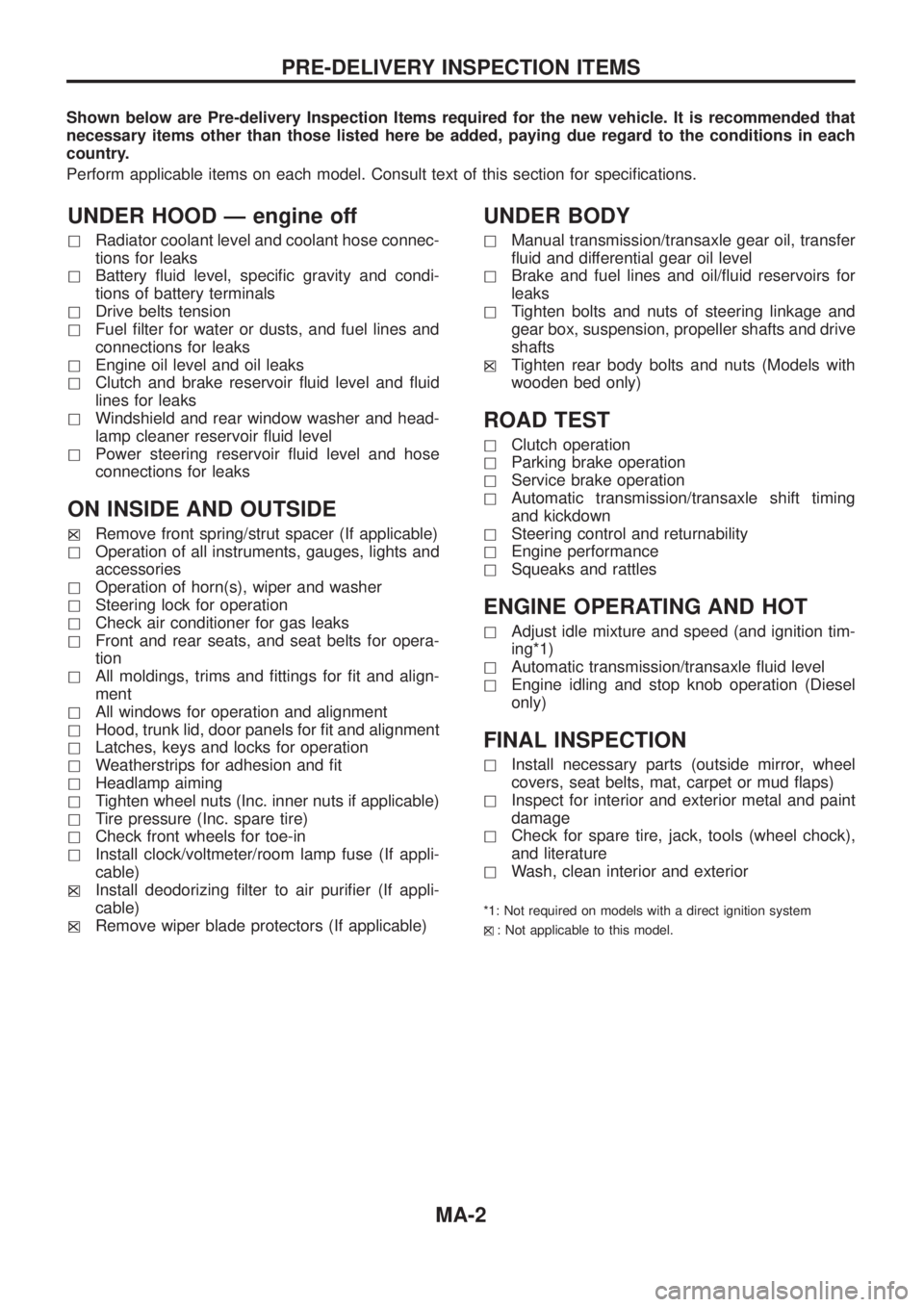
Shown below are Pre-delivery Inspection Items required for the new vehicle. It is recommended that
necessary items other than those listed here be added, paying due regard to the conditions in each
country.
Perform applicable items on each model. Consult text of this section for speci®cations.
UNDER HOOD Ð engine off
hRadiator coolant level and coolant hose connec-
tions for leaks
hBattery ¯uid level, speci®c gravity and condi-
tions of battery terminals
hDrive belts tension
hFuel ®lter for water or dusts, and fuel lines and
connections for leaks
hEngine oil level and oil leaks
hClutch and brake reservoir ¯uid level and ¯uid
lines for leaks
hWindshield and rear window washer and head-
lamp cleaner reservoir ¯uid level
hPower steering reservoir ¯uid level and hose
connections for leaks
ON INSIDE AND OUTSIDE
hXRemove front spring/strut spacer (If applicable)
hOperation of all instruments, gauges, lights and
accessories
hOperation of horn(s), wiper and washer
hSteering lock for operation
hCheck air conditioner for gas leaks
hFront and rear seats, and seat belts for opera-
tion
hAll moldings, trims and ®ttings for ®t and align-
ment
hAll windows for operation and alignment
hHood, trunk lid, door panels for ®t and alignment
hLatches, keys and locks for operation
hWeatherstrips for adhesion and ®t
hHeadlamp aiming
hTighten wheel nuts (Inc. inner nuts if applicable)
hTire pressure (Inc. spare tire)
hCheck front wheels for toe-in
hInstall clock/voltmeter/room lamp fuse (If appli-
cable)
h
XInstall deodorizing ®lter to air puri®er (If appli-
cable)
h
XRemove wiper blade protectors (If applicable)
UNDER BODY
hManual transmission/transaxle gear oil, transfer
¯uid and differential gear oil level
hBrake and fuel lines and oil/¯uid reservoirs for
leaks
hTighten bolts and nuts of steering linkage and
gear box, suspension, propeller shafts and drive
shafts
h
XTighten rear body bolts and nuts (Models with
wooden bed only)
ROAD TEST
hClutch operation
hParking brake operation
hService brake operation
hAutomatic transmission/transaxle shift timing
and kickdown
hSteering control and returnability
hEngine performance
hSqueaks and rattles
ENGINE OPERATING AND HOT
hAdjust idle mixture and speed (and ignition tim-
ing*1)
hAutomatic transmission/transaxle ¯uid level
hEngine idling and stop knob operation (Diesel
only)
FINAL INSPECTION
hInstall necessary parts (outside mirror, wheel
covers, seat belts, mat, carpet or mud ¯aps)
hInspect for interior and exterior metal and paint
damage
hCheck for spare tire, jack, tools (wheel chock),
and literature
hWash, clean interior and exterior
*1: Not required on models with a direct ignition system
h
X: Not applicable to this model.
PRE-DELIVERY INSPECTION ITEMS
MA-2
Page 983 of 1226
![NISSAN PATROL 2006 Service Manual Chassis and Body Services
Annual driving distance below 30,000 km (18,000 miles)
Abbreviations: R = Replace, I = Inspect, and correct or replace as necessary, L = Lubricate,T=Tighten.
[ ]: At the spec NISSAN PATROL 2006 Service Manual Chassis and Body Services
Annual driving distance below 30,000 km (18,000 miles)
Abbreviations: R = Replace, I = Inspect, and correct or replace as necessary, L = Lubricate,T=Tighten.
[ ]: At the spec](/manual-img/5/57368/w960_57368-982.png)
Chassis and Body Services
Annual driving distance below 30,000 km (18,000 miles)
Abbreviations: R = Replace, I = Inspect, and correct or replace as necessary, L = Lubricate,T=Tighten.
[ ]: At the speci®ed mileage only
MAINTENANCE OPERATIONMAINTENANCE INTERVAL
Reference
page Perform either at number of kilometers (miles) or months,
whichever comes ®rst.km x 1,000 10 20 30 40 50 60 70 80 90
(Miles x 1,000) (6) (12) (18) (24) (30) (36) (42) (48) (54)
Months 6 12 18 24 30 36 42 48 54
CHASSIS AND BODY Underhood and under vehicle
Brake & clutch ¯uid (For level & leaks).I I I I MA-23, 20
Brake ¯uid.R R MA-24
Brake booster vacuum hoses, connections & check valve I I MA-24
Power steering ¯uid & lines (For level & leaks) I I I I MA-26
Brake & clutch systemsI I I I MA-24, 20
Manual transmission oil (For leaks) I I I I MA-20
Manual transmission oil[R] MA-20
Transfer ¯uidI I R I MA-21
Limited slip differential (LSD) gear oil (For level & leaks).*1 I I R I MA-22
Steering gear & linkage, axle & suspension parts, propeller shaft & exhaust system.I I I I MA-26, 20 *2
Greasing points of propeller shaftLLLLMA-21
Drive shafts & steering damper.IIII *3
Body mounting bolts & nutsTTTT *4
Outside and Inside
Wheel alignment (If necessary, rotate & balance wheels) I I I I MA-25, *5
Brake pads, discs & other brake components.I I I I MA-24
Front wheel bearing grease I R I R MA-22
Axle joint in knuckle ¯angeL L MA-23
Free running hub greaseI I I I MA-23
Headlamp aimingIIII *6
Foot brake, parking brake & clutch (For free play, stroke & operation) I I I I *7
Ventilation air ®lterRRR*8
Body corrosionAnnually MA-28
Air bag systemSee NOTE (1) *9
NOTE: (1) Inspect after 10 years, then every 2 years.
(2) Maintenance items with ``.'' should be performed more frequently according to ``Maintenance Under Severe Driv-
ing Conditions''.
*1: Including differential gear with differential lock
*2: ``Front Axle and Front Suspension Parts'' in FA section, ``Rear Axle and Rear Suspension Parts'' in RA section
*3: ``FRONT AXLE Ð Drive Shaft'' in FA section
*4: ``CAB BODY'' in BT section
*5: ``Front Wheel Alignment'' in FA section
*6: ``Aiming Adjustment'' in EL section
*7: ``Brake Pedal and Bracket'' in BR section, ``Adjusting Clutch Pedal'' in CL section
*8: ``Ventilation air ®lter'' in HA section
*9: ``Maintenance Items'' in RS section
PERIODIC MAINTENANCE
MA-6
Page 984 of 1226
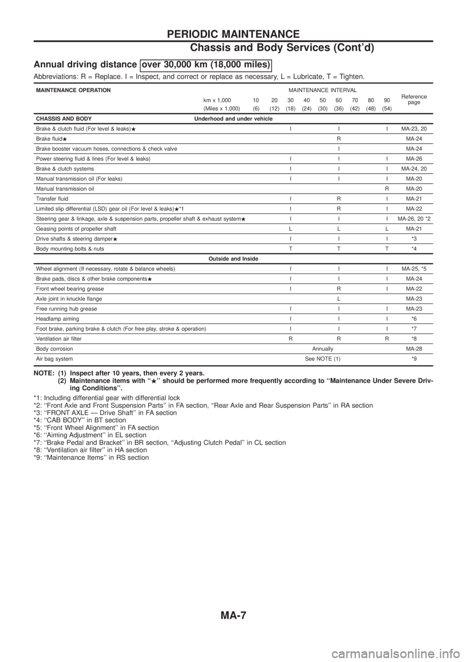
Annual driving distance over 30,000 km (18,000 miles)
Abbreviations: R = Replace. I = Inspect, and correct or replace as necessary, L = Lubricate,T=Tighten.
MAINTENANCE OPERATIONMAINTENANCE INTERVAL
Reference
page km x 1,000 10 20 30 40 50 60 70 80 90
(Miles x 1,000) (6) (12) (18) (24) (30) (36) (42) (48) (54)
CHASSIS AND BODY Underhood and under vehicle
Brake & clutch ¯uid (For level & leaks).I I I MA-23, 20
Brake ¯uid.R MA-24
Brake booster vacuum hoses, connections & check valve I MA-24
Power steering ¯uid & lines (For level & leaks) I I I MA-26
Brake & clutch systemsI I I MA-24, 20
Manual transmission oil (For leaks) I I I MA-20
Manual transmission oilR MA-20
Transfer ¯uidI R I MA-21
Limited slip differential (LSD) gear oil (For level & leaks).*1 I R I MA-22
Steering gear & linkage, axle & suspension parts, propeller shaft & exhaust system.I I I MA-26, 20 *2
Geasing points of propeller shaft L L L MA-21
Drive shafts & steering damper.III*3
Body mounting bolts & nutsTTT*4
Outside and Inside
Wheel alignment (If necessary, rotate & balance wheels) I I I MA-25, *5
Brake pads, discs & other brake components.I I I MA-24
Front wheel bearing greaseI R I MA-22
Axle joint in knuckle ¯angeL MA-23
Free running hub greaseI I I MA-23
Headlamp aimingIII*6
Foot brake, parking brake & clutch (For free play, stroke & operation) I I I *7
Ventilation air ®lterRRR*8
Body corrosionAnnually MA-28
Air bag systemSee NOTE (1) *9
NOTE: (1) Inspect after 10 years, then every 2 years.
(2) Maintenance items with ``.'' should be performed more frequently according to ``Maintenance Under Severe Driv-
ing Conditions''.
*1: Including differential gear with differential lock
*2: ``Front Axle and Front Suspension Parts'' in FA section, ``Rear Axle and Rear Suspension Parts'' in RA section
*3: ``FRONT AXLE Ð Drive Shaft'' in FA section
*4: ``CAB BODY'' in BT section
*5: ``Front Wheel Alignment'' in FA section
*6: ``Aiming Adjustment'' in EL section
*7: ``Brake Pedal and Bracket'' in BR section, ``Adjusting Clutch Pedal'' in CL section
*8: ``Ventilation air ®lter'' in HA section
*9: ``Maintenance Items'' in RS section
PERIODIC MAINTENANCE
Chassis and Body Services (Cont'd)
MA-7