2006 NISSAN PATROL steering
[x] Cancel search: steeringPage 736 of 1226
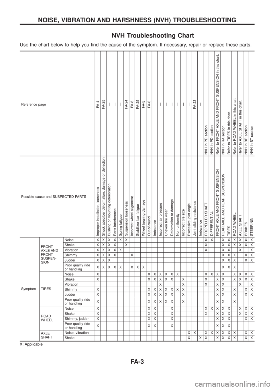
NVH Troubleshooting Chart
Use the chart below to help you ®nd the cause of the symptom. If necessary, repair or replace these parts.
Reference pageFA-4
FA-25
Ð
Ð
Ð
FA-24
FA-8
FA-25
FA-5
FA-8
Ð
Ð
Ð
Ð
Ð
Ð
Ð
FA-23
Ð
NVH in PD section
NVH in PD section
Refer to FRONT AXLE AND FRONT SUSPENSION in this chart.
NVH in RA section
Refer to TIRES in this chart.
Refer to ROAD WHEEL in this chart.
Refer to AXLE SHAFT in this chart.
NVH in BR section
NVH in ST section
Possible cause and SUSPECTED PARTS
Improper installation, looseness
Shock absorber deformation, damage or de¯ection
Bushing or mounting deterioration
Parts interference
Spring fatigue
Suspension looseness
Incorrect wheel alignment
Stabilizer bar fatigue
Wheel bearing damage
Out-of-round
Imbalance
Incorrect air pressure
Uneven tire wear
Deformation or damage
Non-uniformity
Incorrect tire size
Excessive joint angle
Joint sliding resistance
Imbalance
PROPELLER SHAFT
DIFFERENTIAL
FRONT AXLE AND FRONT SUSPENSION
REAR AXLE AND REAR SUSPENSION
TIRES
ROAD WHEEL
AXLE SHAFT
BRAKES
STEERING
SymptomFRONT
AXLE AND
FRONT
SUSPEN-
SIONNoiseXXXXXX XX XXXXXX
ShakeXXXX X X XXXXXX
VibrationXXXXX X XX X X
ShimmyXXXX X XXX XX
Judder X X XXXX XX
Poor quality ride
or handlingXXXXX XXX XXX
TIRESNoise XXXXXXX XXXX XXXX
Shake XXXXXX X X XX XXXX
Vibration X X X X X X X
Shimmy XXXXXXXX XX X XX
Judder XXXXXX X XX X XX
Poor quality ride
or handlingX XXXXX X XX X
ROAD
WHEELNoise X X X XXXXXX XXX
Shake X X X X X X X X X X X
Shimmy, judder X X X X X X X X X
Poor quality ride
or handlingX XX X XXX
AXLE
SHAFTNoise, vibration X XXXXXXX XX
ShakeX XX XXXX XX
X: Applicable
NOISE, VIBRATION AND HARSHNESS (NVH) TROUBLESHOOTING
FA-3
Page 741 of 1226
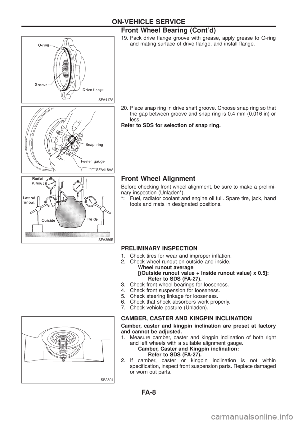
19. Pack drive ¯ange groove with grease, apply grease to O-ring
and mating surface of drive ¯ange, and install ¯ange.
20. Place snap ring in drive shaft groove. Choose snap ring so that
the gap between groove and snap ring is 0.4 mm (0.016 in) or
less.
Refer to SDS for selection of snap ring.
Front Wheel Alignment
Before checking front wheel alignment, be sure to make a prelimi-
nary inspection (Unladen*).
*: Fuel, radiator coolant and engine oil full. Spare tire, jack, hand
tools and mats in designated positions.
PRELIMINARY INSPECTION
1. Check tires for wear and improper in¯ation.
2. Check wheel runout on outside and inside.
Wheel runout average
[(Outside runout value + Inside runout value) x 0.5]:
Refer to SDS (FA-27).
3. Check front wheel bearings for looseness.
4. Check front suspension for looseness.
5. Check steering linkage for looseness.
6. Check that shock absorbers work properly.
7. Check vehicle posture (Unladen).
CAMBER, CASTER AND KINGPIN INCLINATION
Camber, caster and kingpin inclination are preset at factory
and cannot be adjusted.
1. Measure camber, caster and kingpin inclination of both right
and left wheels with a suitable alignment gauge.
Camber, Caster and Kingpin inclination:
Refer to SDS (FA-27).
2. If camber, caster or kingpin inclination is not within
speci®cation, inspect front suspension parts. Replace damaged
or worn out parts.
SFA417A
SFA418AA
SFA356B
SFA894
ON-VEHICLE SERVICE
Front Wheel Bearing (Cont'd)
FA-8
Page 742 of 1226
TOE-IN
Measure toe-in using the following procedure.
WARNING:
+Always perform the following procedure on a ¯at surface.
+Make sure that no person is in front of the vehicle before
pushing it.
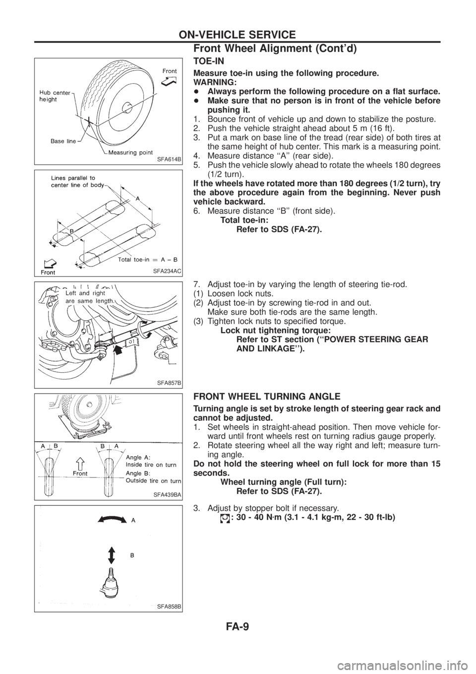
1. Bounce front of vehicle up and down to stabilize the posture.
2. Push the vehicle straight ahead about 5 m (16 ft).
3. Put a mark on base line of the tread (rear side) of both tires at
the same height of hub center. This mark is a measuring point.
4. Measure distance ``A'' (rear side).
5. Push the vehicle slowly ahead to rotate the wheels 180 degrees
(1/2 turn).
If the wheels have rotated more than 180 degrees (1/2 turn), try
the above procedure again from the beginning. Never push
vehicle backward.
6. Measure distance ``B'' (front side).
Total toe-in:
Refer to SDS (FA-27).
7. Adjust toe-in by varying the length of steering tie-rod.
(1) Loosen lock nuts.
(2) Adjust toe-in by screwing tie-rod in and out.
Make sure both tie-rods are the same length.
(3) Tighten lock nuts to speci®ed torque.
Lock nut tightening torque:
Refer to ST section (``POWER STEERING GEAR
AND LINKAGE'').
FRONT WHEEL TURNING ANGLE
Turning angle is set by stroke length of steering gear rack and
cannot be adjusted.
1. Set wheels in straight-ahead position. Then move vehicle for-
ward until front wheels rest on turning radius gauge properly.
2. Rotate steering wheel all the way right and left; measure turn-
ing angle.
Do not hold the steering wheel on full lock for more than 15
seconds.
Wheel turning angle (Full turn):
Refer to SDS (FA-27).
3. Adjust by stopper bolt if necessary.
:30-40Nzm (3.1 - 4.1 kg-m, 22 - 30 ft-lb)
SFA614B
SFA234AC
SFA857B
SFA439BA
SFA858B
ON-VEHICLE SERVICE
Front Wheel Alignment (Cont'd)
FA-9
Page 754 of 1226
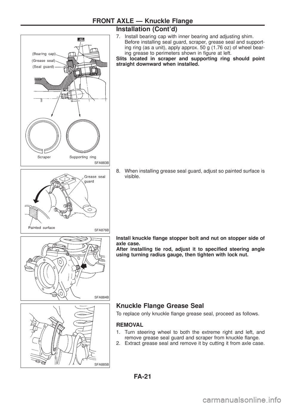
7. Install bearing cap with inner bearing and adjusting shim.
Before installing seal guard, scraper, grease seal and support-
ing ring (as a unit), apply approx. 50 g (1.76 oz) of wheel bear-
ing grease to perimeters shown in ®gure at left.
Slits located in scraper and supporting ring should point
straight downward when installed.
8. When installing grease seal guard, adjust so painted surface is
visible.
Install knuckle ¯ange stopper bolt and nut on stopper side of
axle case.
After installing tie rod, adjust it to speci®ed steering angle
using turning radius gauge, then tighten with lock nut.
Knuckle Flange Grease Seal
To replace only knuckle ¯ange grease seal, proceed as follows.
REMOVAL
1. Turn steering wheel to both the extreme right and left, and
remove grease seal guard and scraper from knuckle ¯ange.
2. Extract grease seal and remove it by cutting it from axle case.
SFA883B
SFA876B
SFA884B
SFA885B
FRONT AXLE Ð Knuckle Flange
Installation (Cont'd)
FA-21
Page 755 of 1226
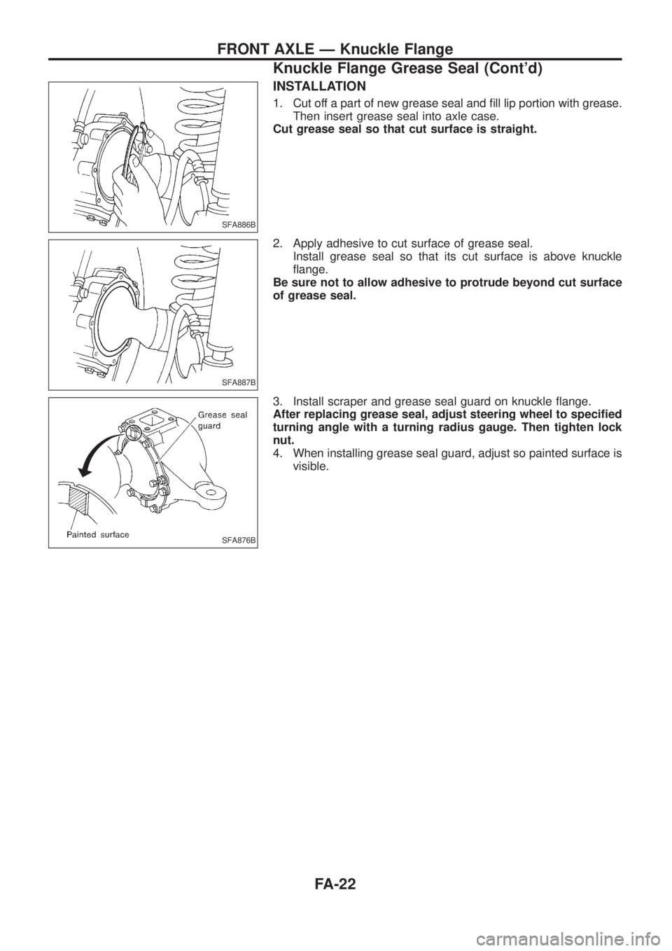
INSTALLATION
1. Cut off a part of new grease seal and ®ll lip portion with grease.
Then insert grease seal into axle case.
Cut grease seal so that cut surface is straight.
2. Apply adhesive to cut surface of grease seal.
Install grease seal so that its cut surface is above knuckle
¯ange.
Be sure not to allow adhesive to protrude beyond cut surface
of grease seal.
3. Install scraper and grease seal guard on knuckle ¯ange.
After replacing grease seal, adjust steering wheel to speci®ed
turning angle with a turning radius gauge. Then tighten lock
nut.
4. When installing grease seal guard, adjust so painted surface is
visible.
SFA886B
SFA887B
SFA876B
FRONT AXLE Ð Knuckle Flange
Knuckle Flange Grease Seal (Cont'd)
FA-22
Page 760 of 1226
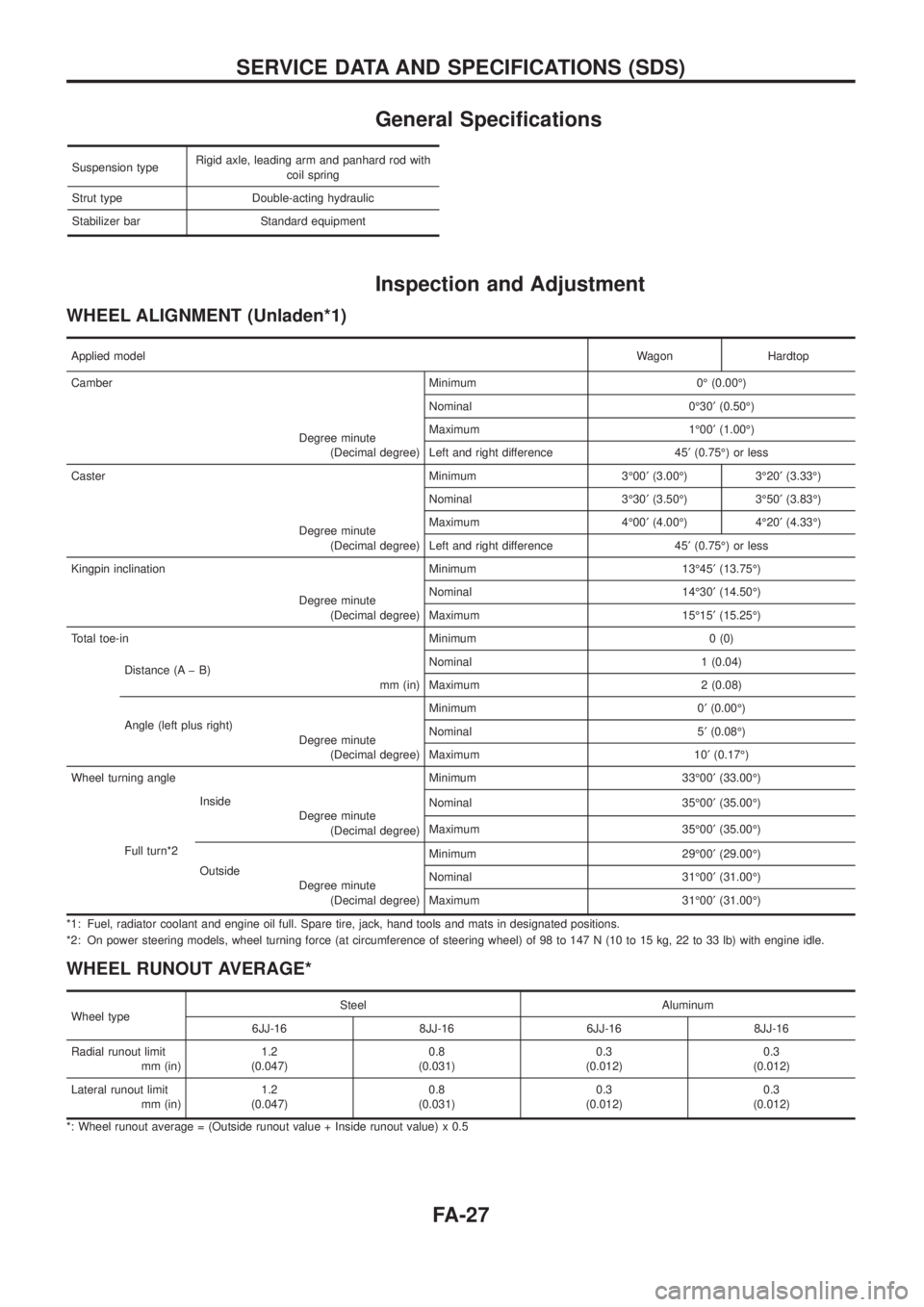
General Speci®cations
Suspension typeRigid axle, leading arm and panhard rod with
coil spring
Strut type Double-acting hydraulic
Stabilizer bar Standard equipment
Inspection and Adjustment
WHEEL ALIGNMENT (Unladen*1)
Applied modelWagon Hardtop
Camber Minimum 0É (0.00É)
Degree minute
(Decimal degree)Nominal 0É30¢(0.50É)
Maximum 1É00¢(1.00É)
Left and right difference 45¢(0.75É) or less
Caster Minimum 3É00¢(3.00É) 3É20¢(3.33É)
Degree minute
(Decimal degree)Nominal 3É30¢(3.50É) 3É50¢(3.83É)
Maximum 4É00¢(4.00É) 4É20¢(4.33É)
Left and right difference 45¢(0.75É) or less
Kingpin inclination Minimum 13É45¢(13.75É)
Degree minute
(Decimal degree)Nominal 14É30¢(14.50É)
Maximum 15É15¢(15.25É)
Total toe-in Minimum 0 (0)
Distance (A þ B)
mm (in)Nominal 1 (0.04)
Maximum 2 (0.08)
Angle (left plus right)
Degree minute
(Decimal degree)Minimum 0¢(0.00É)
Nominal 5¢(0.08É)
Maximum 10¢(0.17É)
Wheel turning angle Minimum 33É00¢(33.00É)
Full turn*2Inside
Degree minute
(Decimal degree)Nominal 35É00¢(35.00É)
Maximum 35É00¢(35.00É)
Outside
Degree minute
(Decimal degree)Minimum 29É00¢(29.00É)
Nominal 31É00¢(31.00É)
Maximum 31É00¢(31.00É)
*1: Fuel, radiator coolant and engine oil full. Spare tire, jack, hand tools and mats in designated positions.
*2: On power steering models, wheel turning force (at circumference of steering wheel) of 98 to 147 N (10 to 15 kg, 22 to 33 lb) with engine idle.
WHEEL RUNOUT AVERAGE*
Wheel typeSteel Aluminum
6JJ-16 8JJ-16 6JJ-16 8JJ-16
Radial runout limit
mm (in)1.2
(0.047)0.8
(0.031)0.3
(0.012)0.3
(0.012)
Lateral runout limit
mm (in)1.2
(0.047)0.8
(0.031)0.3
(0.012)0.3
(0.012)
*: Wheel runout average = (Outside runout value + Inside runout value) x 0.5
SERVICE DATA AND SPECIFICATIONS (SDS)
FA-27
Page 774 of 1226
Observe the following precautions to ensure safe and proper
servicing. These precautions are not described in each indi-
vidual section.
Precaution for Supplemental Restraint System
(SRS) ``AIR BAG'' and ``SEAT BELT
PRE-TENSIONER''
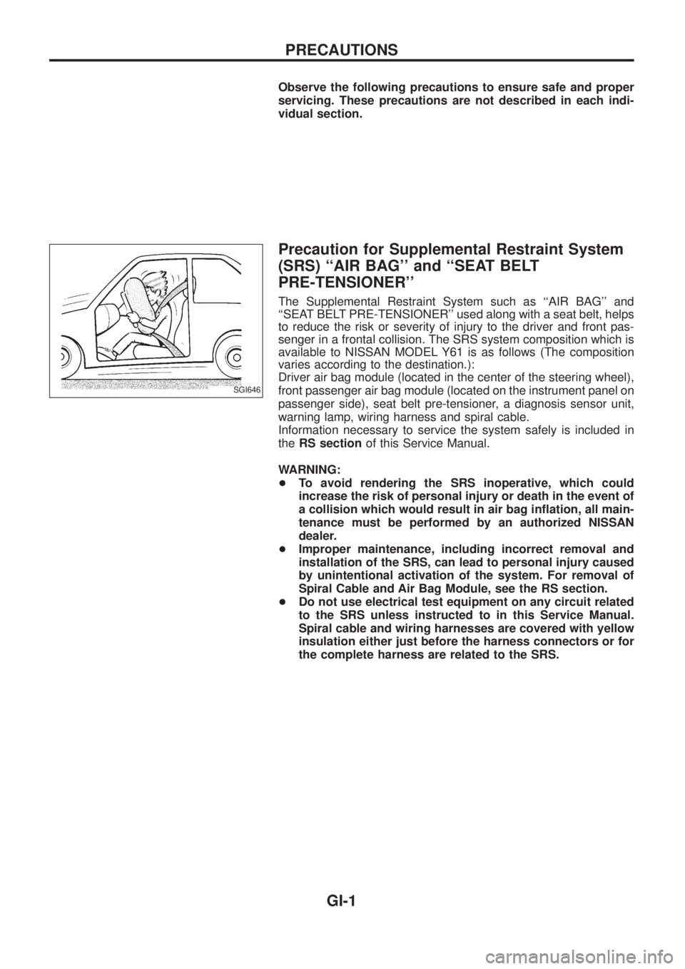
The Supplemental Restraint System such as ``AIR BAG'' and
``SEAT BELT PRE-TENSIONER'' used along with a seat belt, helps
to reduce the risk or severity of injury to the driver and front pas-
senger in a frontal collision. The SRS system composition which is
available to NISSAN MODEL Y61 is as follows (The composition
varies according to the destination.):
Driver air bag module (located in the center of the steering wheel),
front passenger air bag module (located on the instrument panel on
passenger side), seat belt pre-tensioner, a diagnosis sensor unit,
warning lamp, wiring harness and spiral cable.
Information necessary to service the system safely is included in
theRS sectionof this Service Manual.
WARNING:
+To avoid rendering the SRS inoperative, which could
increase the risk of personal injury or death in the event of
a collision which would result in air bag in¯ation, all main-
tenance must be performed by an authorized NISSAN
dealer.
+Improper maintenance, including incorrect removal and
installation of the SRS, can lead to personal injury caused
by unintentional activation of the system. For removal of
Spiral Cable and Air Bag Module, see the RS section.
+Do not use electrical test equipment on any circuit related
to the SRS unless instructed to in this Service Manual.
Spiral cable and wiring harnesses are covered with yellow
insulation either just before the harness connectors or for
the complete harness are related to the SRS.
SGI646
PRECAUTIONS
GI-1
Page 780 of 1226
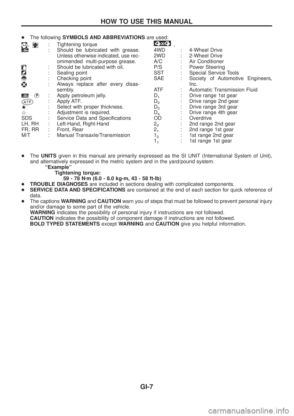
+The followingSYMBOLS AND ABBREVIATIONSare used:
,: Tightening torque
: Should be lubricated with grease.
Unless otherwise indicated, use rec-
ommended multi-purpose grease.
: Should be lubricated with oil.
: Sealing point
: Checking point
: Always replace after every disas-
sembly.
jP: Apply petroleum jelly.
: Apply ATF.
.: Select with proper thickness.
>: Adjustment is required.
SDS : Service Data and Speci®cations
LH, RH : Left-Hand, Right-Hand
FR, RR : Front, Rear
M/T : Manual Transaxle/Transmission
,
4WD : 4-Wheel Drive
2WD : 2-Wheel Drive
A/C : Air Conditioner
P/S : Power Steering
SST : Special Service Tools
SAE : Society of Automotive Engineers,
Inc.
ATF : Automatic Transmission Fluid
D
1: Drive range 1st gear
D
2: Drive range 2nd gear
D
3: Drive range 3rd gear
D
4: Drive range 4th gear
OD : Overdrive
2
2: 2nd range 2nd gear
2
1: 2nd range 1st gear
1
2: 1st range 2nd gear
1
1: 1st range 1st gear
+TheUNITSgiven in this manual are primarily expressed as the SI UNIT (International System of Unit),
and alternatively expressed in the metric system and in the yard/pound system.
``Example''
Tightening torque:
59-78Nzm (6.0 - 8.0 kg-m, 43 - 58 ft-lb)
+TROUBLE DIAGNOSESare included in sections dealing with complicated components.
+SERVICE DATA AND SPECIFICATIONSare contained at the end of each section for quick reference of
data.
+The captionsWARNINGandCAUTIONwarn you of steps that must be followed to prevent personal injury
and/or damage to some part of the vehicle.
WARNINGindicates the possibility of personal injury if instructions are not followed.
CAUTIONindicates the possibility of component damage if instructions are not followed.
BOLD TYPED STATEMENTSexceptWARNINGandCAUTIONgive you helpful information.
HOW TO USE THIS MANUAL
GI-7