2006 NISSAN PATROL electrical circuit
[x] Cancel search: electrical circuitPage 430 of 1226
Trouble Diagnoses
Symptom Possible cause Repair order
Turn signal and hazard warning
lamps do not operate.1. Hazard switch
2. Combination ¯asher unit
3. Open in combination ¯asher unit
circuit1. Check hazard switch.
2. Refer to combination ¯asher unit check.
3. Check wiring to combination ¯asher unit for open cir-
cuit.
Turn signal lamps do not operate
but hazard warning lamps operate.1. 7.5A fuse
2. Hazard switch
3. Turn signal switch
4. Open in turn signal switch circuit1. Check 7.5A fuse [No.
11, located in fuse block
(J/B)]. Turn ignition switch ON and verify battery
positive voltage is present at terminalj
2of hazard
switch.
2. Check hazard switch.
3. Check turn signal switch.
4. Check harness between combination ¯asher unit and
turn signal switch for open circuit.
Hazard warning lamps do not oper-
ate but turn signal lamps operate.1. 15A fuse
2. Hazard switch
3. Open in hazard switch circuit1. Check 10A fuse (No.
48, located in fuse and fusible
link box). Verify battery positive voltage is present at
terminalj
3of hazard switch.
2. Check hazard switch.
3. Check harness between combination ¯asher unit and
hazard switch for open circuit.
Front turn signal lamp LH or RH
does not operate.1. Bulb
2. Grounds
E25andE40
1. Check bulb.
2. Check grounds
E25andE40.
Rear turn signal lamp LH or RH
does not operate.1. Bulb
2. Grounds
B23andD83or
B112andD106
1. Check bulb.
2. Check grounds
B23andD83orB112andD106.
LH and RH turn indicators do not
operate.1. Ground 1. Check grounds
M30andM98.
LH or RH turn indicator does not
operate.1. Bulb 1. Check bulb in combination meter.
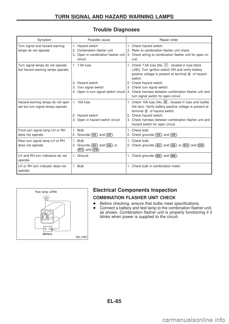
Electrical Components Inspection
COMBINATION FLASHER UNIT CHECK
+Before checking, ensure that bulbs meet speci®cations.
+Connect a battery and test lamp to the combination ¯asher unit,
as shown. Combination ¯asher unit is properly functioning if it
blinks when power is supplied to the circuit.
SEL122E
TURN SIGNAL AND HAZARD WARNING LAMPS
EL-85
Page 459 of 1226
INSPECTION/THERMAL TRANSMITTER
CHECK THERMAL TRANSMITTER.
Refer to ``THERMAL TRANSMITTER
CHECK'' (EL-115).
OK
cNG
Repair or replace.
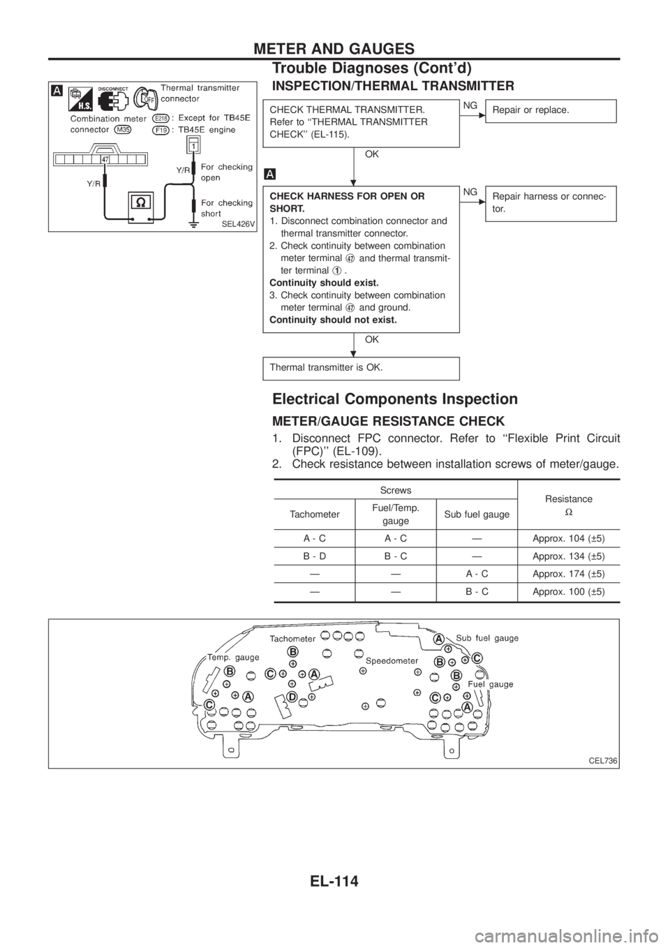
CHECK HARNESS FOR OPEN OR
SHORT.
1. Disconnect combination connector and
thermal transmitter connector.
2. Check continuity between combination
meter terminalj
47and thermal transmit-
ter terminalj
1.
Continuity should exist.
3. Check continuity between combination
meter terminalj
47and ground.
Continuity should not exist.
OK
cNG
Repair harness or connec-
tor.
Thermal transmitter is OK.
Electrical Components Inspection
METER/GAUGE RESISTANCE CHECK
1. Disconnect FPC connector. Refer to ``Flexible Print Circuit
(FPC)'' (EL-109).
2. Check resistance between installation screws of meter/gauge.
Screws
Resistance
W
TachometerFuel/Temp.
gaugeSub fuel gauge
A - C A - C Ð Approx. 104 ( 5)
B - D B - C Ð Approx. 134 ( 5)
Ð Ð A - C Approx. 174 ( 5)
Ð Ð B - C Approx. 100 ( 5)
SEL426V
CEL736
.
.
METER AND GAUGES
Trouble Diagnoses (Cont'd)
EL-114
Page 479 of 1226
Electrical Components Inspection
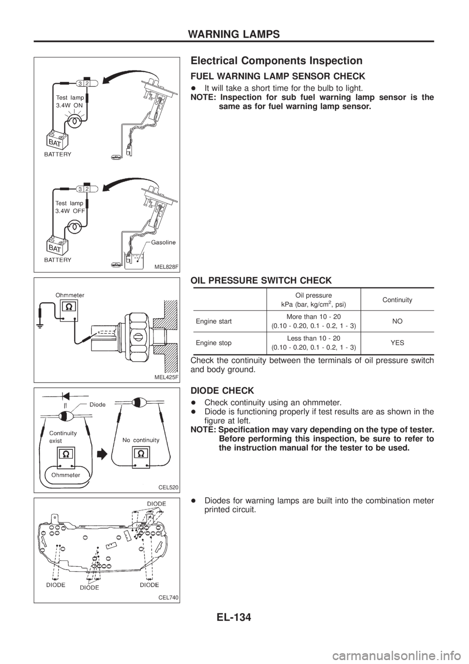
FUEL WARNING LAMP SENSOR CHECK
+It will take a short time for the bulb to light.
NOTE: Inspection for sub fuel warning lamp sensor is the
same as for fuel warning lamp sensor.
OIL PRESSURE SWITCH CHECK
Oil pressure
kPa (bar, kg/cm2, psi)Continuity
Engine startMore than 10 - 20
(0.10 - 0.20, 0.1 - 0.2,1-3)NO
Engine stopLess than 10 - 20
(0.10 - 0.20, 0.1 - 0.2,1-3)YES
Check the continuity between the terminals of oil pressure switch
and body ground.
DIODE CHECK
+Check continuity using an ohmmeter.
+Diode is functioning properly if test results are as shown in the
®gure at left.
NOTE: Speci®cation may vary depending on the type of tester.
Before performing this inspection, be sure to refer to
the instruction manual for the tester to be used.
+Diodes for warning lamps are built into the combination meter
printed circuit.
MEL828F
MEL425F
CEL520
CEL740
WARNING LAMPS
EL-134
Page 484 of 1226
DIAGNOSTIC PROCEDURE 2
(Key switch input signal check)
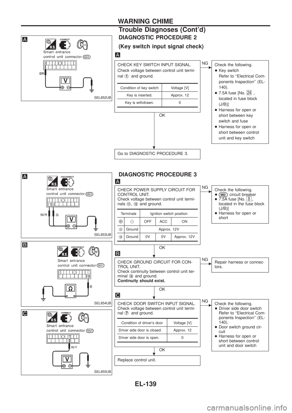
CHECK KEY SWITCH INPUT SIGNAL.
Check voltage between control unit termi-
nalj
1and ground.
OK
cNG
Check the following.
+Key switch
Refer to ``Electrical Com-
ponents Inspection'' (EL-
140).
+7.5A fuse [No.
24,
located in fuse block
(J/B)]
+Harness for open or
short between key
switch and fuse
+Harness for open or
short between control
unit and key switch
Go to DIAGNOSTIC PROCEDURE 3.
Condition of key switch Voltage [V]
Key is inserted. Approx. 12
Key is withdrawn. 0
DIAGNOSTIC PROCEDURE 3
CHECK POWER SUPPLY CIRCUIT FOR
CONTROL UNIT.
Check voltage between control unit termi-
nalsj
11,j12and ground.
OK
cNG
Check the following.
+
M92circuit breaker
+7.5A fuse [No.8,
located in the fuse block
(J/B)]
+Harness for open or
short
CHECK GROUND CIRCUIT FOR CON-
TROL UNIT.
Check continuity between control unit ter-
minalj
18and ground.
Continuity should exist.
OK
cNG
Repair harness or connec-
tors.
CHECK DOOR SWITCH INPUT SIGNAL.
Check voltage between control unit termi-
nalj
7and ground.
OK
cNG
Check the following.
+Driver side door switch
Refer to ``Electrical Com-
ponents Inspection'' (EL-
140).
+Door switch ground cir-
cuit
+Harness for open or
short between control
unit and door switch
Replace control unit.
Terminals Ignition switch position
Å@OFF ACC ON
j
11Ground Approx. 12V
j
12Ground 0V 0V Approx. 12V
Condition of driver's door Voltage [V]
Driver side door is closed. Approx. 12
Driver side door is open. 0
SEL852UB
SEL853UB
SEL854UB
SEL855UB
.
.
.
.
WARNING CHIME
Trouble Diagnoses (Cont'd)
EL-139
Page 499 of 1226
Electrical Components Inspection
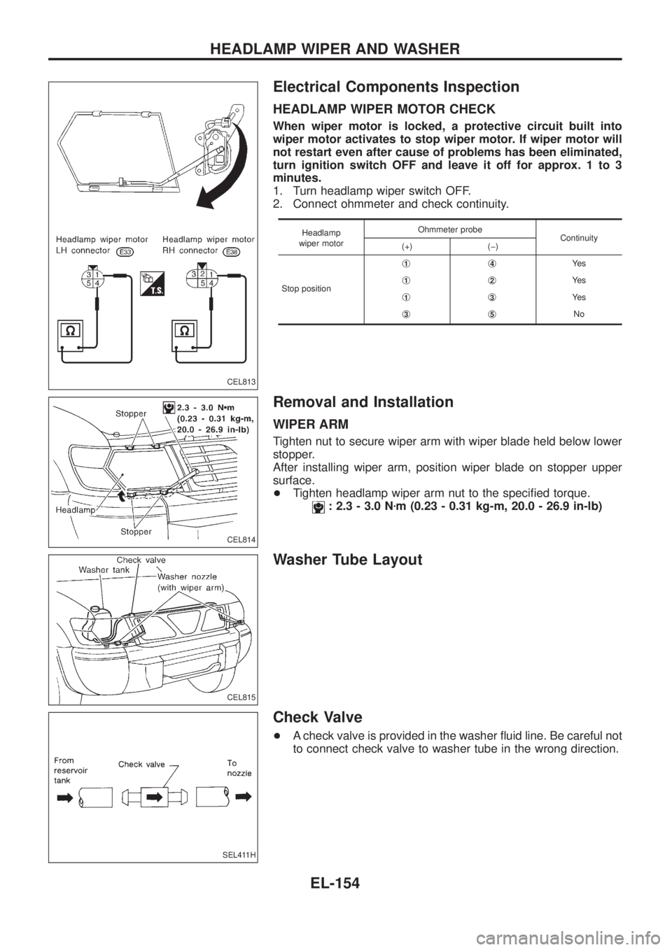
HEADLAMP WIPER MOTOR CHECK
When wiper motor is locked, a protective circuit built into
wiper motor activates to stop wiper motor. If wiper motor will
not restart even after cause of problems has been eliminated,
turn ignition switch OFF and leave it off for approx. 1 to 3
minutes.
1. Turn headlamp wiper switch OFF.
2. Connect ohmmeter and check continuity.
Headlamp
wiper motorOhmmeter probe
Continuity
(+) (þ)
Stop positionj
1j4Ye s
j
1j2Ye s
j
1j3Ye s
j
3j5No
Removal and Installation
WIPER ARM
Tighten nut to secure wiper arm with wiper blade held below lower
stopper.
After installing wiper arm, position wiper blade on stopper upper
surface.
+Tighten headlamp wiper arm nut to the speci®ed torque.
: 2.3 - 3.0 Nzm (0.23 - 0.31 kg-m, 20.0 - 26.9 in-lb)
Washer Tube Layout
Check Valve
+A check valve is provided in the washer ¯uid line. Be careful not
to connect check valve to washer tube in the wrong direction.
CEL813
CEL814
CEL815
SEL411H
HEADLAMP WIPER AND WASHER
EL-154
Page 509 of 1226
Electrical Components Inspection
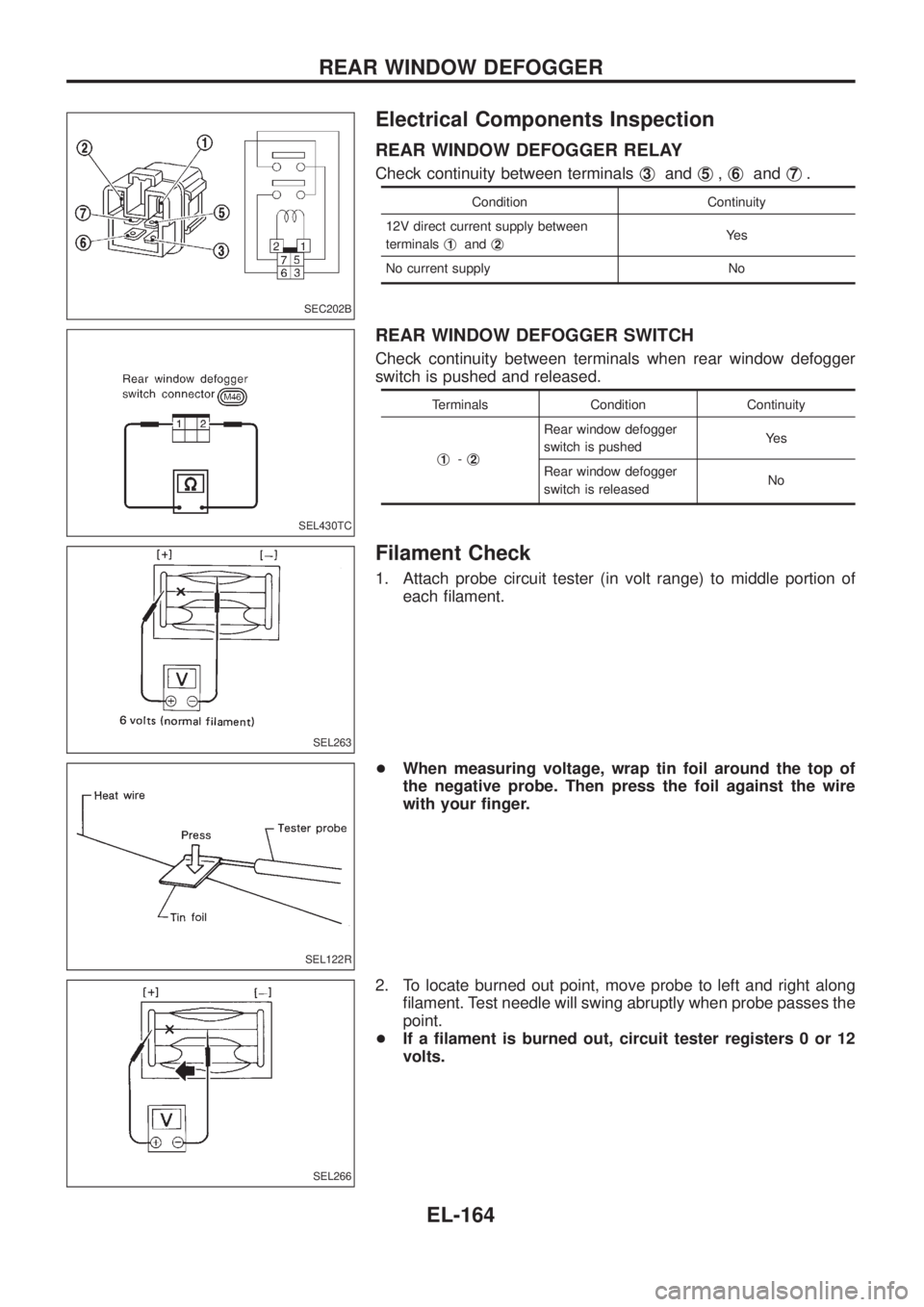
REAR WINDOW DEFOGGER RELAY
Check continuity between terminalsj3andj5,j6andj7.
Condition Continuity
12V direct current supply between
terminalsj
1andj2Ye s
No current supply No
REAR WINDOW DEFOGGER SWITCH
Check continuity between terminals when rear window defogger
switch is pushed and released.
Terminals Condition Continuity
j
1-j2
Rear window defogger
switch is pushedYe s
Rear window defogger
switch is releasedNo
Filament Check
1. Attach probe circuit tester (in volt range) to middle portion of
each ®lament.
+When measuring voltage, wrap tin foil around the top of
the negative probe. Then press the foil against the wire
with your ®nger.
2. To locate burned out point, move probe to left and right along
®lament. Test needle will swing abruptly when probe passes the
point.
+If a ®lament is burned out, circuit tester registers 0 or 12
volts.
SEC202B
SEL430TC
SEL263
SEL122R
SEL266
REAR WINDOW DEFOGGER
EL-164
Page 773 of 1226
GENERAL INFORMATION
SECTION
GI
CONTENTS
PRECAUTIONS...............................................................1
Precaution for Supplemental Restraint System
(SRS) ``AIR BAG'' and ``SEAT BELT
PRE-TENSIONER'' ......................................................1
General Precautions ....................................................2
Precautions for Multiport Fuel Injection System
or ECCS Engine ..........................................................3
Precautions for Three Way Catalyst
(If so equipped)............................................................4
Precautions for Engine Oils .........................................4
Precautions for Fuel ....................................................5
Precautions for Air Conditioning ..................................5
HOW TO USE THIS MANUAL........................................6
HOW TO READ WIRING DIAGRAMS............................8
Sample/Wiring Diagram Ð EXAMPL Ð......................8
Description .................................................................10
HOW TO CHECK TERMINAL.......................................17
How to Probe Connectors .........................................17
How to Check Enlarged Contact Spring of
Terminal .....................................................................18
Waterproof Connector Inspection ..............................19
Terminal Lock Inspection ...........................................19
HOW TO PERFORM EFFICIENT DIAGNOSIS FOR
AN ELECTRICAL INCIDENT........................................20Work Flow ..................................................................20
Incident Simulation Tests ...........................................21
Circuit Inspection .......................................................24
HOW TO FOLLOW FLOW CHART IN TROUBLE
DIAGNOSES..................................................................30
How to Follow This Flow Chart .................................31
CONSULT CHECKING SYSTEM..................................33
Function and System Application ..............................33
Lithium Battery Replacement ....................................33
Checking Equipment..................................................33
Loading Procedure ....................................................34
CONSULT Data Link Connector (DLC) Circuit..........34
IDENTIFICATION INFORMATION.................................35
Model Variation ..........................................................35
Identi®cation Number .................................................36
Dimensions ................................................................38
Wheels & Tires ..........................................................38
LIFTING POINTS AND TOW TRUCK TOWING...........39
Screw Jack ................................................................39
Garage Jack and Safety Stand .................................39
2-pole Lift ...................................................................40
Tow Truck Towing ......................................................41
SAE J1930 TERMINOLOGY LIST................................43
SAE J1930 Terminology List .....................................43
GI
Page 774 of 1226
Observe the following precautions to ensure safe and proper
servicing. These precautions are not described in each indi-
vidual section.
Precaution for Supplemental Restraint System
(SRS) ``AIR BAG'' and ``SEAT BELT
PRE-TENSIONER''
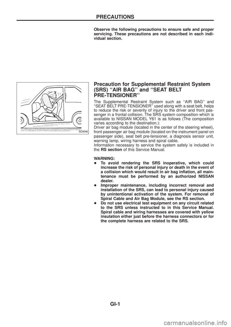
The Supplemental Restraint System such as ``AIR BAG'' and
``SEAT BELT PRE-TENSIONER'' used along with a seat belt, helps
to reduce the risk or severity of injury to the driver and front pas-
senger in a frontal collision. The SRS system composition which is
available to NISSAN MODEL Y61 is as follows (The composition
varies according to the destination.):
Driver air bag module (located in the center of the steering wheel),
front passenger air bag module (located on the instrument panel on
passenger side), seat belt pre-tensioner, a diagnosis sensor unit,
warning lamp, wiring harness and spiral cable.
Information necessary to service the system safely is included in
theRS sectionof this Service Manual.
WARNING:
+To avoid rendering the SRS inoperative, which could
increase the risk of personal injury or death in the event of
a collision which would result in air bag in¯ation, all main-
tenance must be performed by an authorized NISSAN
dealer.
+Improper maintenance, including incorrect removal and
installation of the SRS, can lead to personal injury caused
by unintentional activation of the system. For removal of
Spiral Cable and Air Bag Module, see the RS section.
+Do not use electrical test equipment on any circuit related
to the SRS unless instructed to in this Service Manual.
Spiral cable and wiring harnesses are covered with yellow
insulation either just before the harness connectors or for
the complete harness are related to the SRS.
SGI646
PRECAUTIONS
GI-1