2006 NISSAN PATROL electrical circuit
[x] Cancel search: electrical circuitPage 822 of 1226
Supplemental Restraint System (SRS) ``AIR
BAG'' and ``SEAT BELT PRE-TENSIONER''
The Supplemental Restraint System such as ``AIR BAG'' and ``SEAT BELT PRE-TENSIONER'' used along with
a seat belt, helps to reduce the risk or severity of injury to the driver and front passenger in a frontal collision.
The SRS system composition which is available to NISSAN MODEL Y61 is as follows (The composition var-
ies according to the destination.):
Driver air bag module (located in the center of the steering wheel), front passenger air bag module (located
on the instrument panel on passenger side), seat belt pre-tensioner, a diagnosis sensor unit, warning lamp,
wiring harness and spiral cable.
Information necessary to service the system safely is included in theRS sectionof this Service Manual.
WARNING:
+To avoid rendering the SRS inoperative, which could increase the risk of personal injury or death
in the event of a collision which would result in air bag in¯ation, all maintenance must be performed
by an authorized NISSAN dealer.
+Improper maintenance, including incorrect removal and installation of the SRS, can lead to per-
sonal injury caused by unintentional activation of the system. For removal of Spiral Cable and Air
Bag Module, see the RS section.
+Do not use electrical test equipment on any circuit related to the SRS unless instructed to in this
Service Manual. Spiral cable and wiring harnesses covered with yellow insulation either just before
the harness connectors or for the complete harness are related to the SRS.
Precautions for Working with HFC-134a
(R-134a)
WARNING:
+CFC-12 (R-12) refrigerant and HFC-134a (R-134a) refrigerant are not compatible. These refriger-
ants must never be mixed, even in the smallest amounts. If the refrigerants are mixed, compres-
sor failure is likely to occur.
+Use only speci®ed lubricant for the HFC-134a (R-134a) A/C system and HFC-134a (R-134a) com-
ponents. If lubricant other than that speci®ed is used, compressor failure is likely to occur.
+The speci®ed HFC-134a (R-134a) lubricant rapidly absorbs moisture from the atmosphere. The
following handling precautions must be observed:
a: When removing refrigerant components from a vehicle, immediately cap (seal) the component
to minimize the entry of moisture from the atmosphere.
b: When installing refrigerant components to a vehicle, do not remove the caps (unseal) until
just before connecting the components. Connect all refrigerant loop components as quickly
as possible to minimize the entry of moisture into system.
c: Only use the speci®ed lubricant from a sealed container. Immediately reseal containers of
lubricant. Without proper sealing, lubricant will become moisture saturated and should not
be used.
d: Avoid breathing A/C refrigerant and lubricant vapor or mist. Exposure may irritate eyes, nose
and throat. Use only approved recovery/recycling equipment to discharge HFC-134a (R-134a)
refrigerant. If accidental system discharge occurs, ventilate work area before resuming ser-
vice. Additional health and safety information may be obtained from refrigerant and lubricant
manufacturers.
e: Do not allow lubricant (Nissan A/C System Oil Type S) to come in contact with styrofoam
parts. Damage may result.
PRECAUTIONS AND PREPARATIONMANUAL AND AUTO
HA-1
Page 848 of 1226
jA
Note
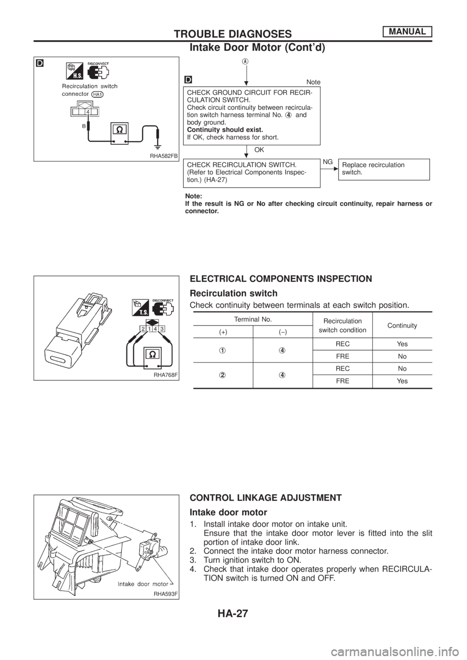
CHECK GROUND CIRCUIT FOR RECIR-
CULATION SWITCH.
Check circuit continuity between recircula-
tion switch harness terminal No.j
4and
body ground.
Continuity should exist.
If OK, check harness for short.
OK
CHECK RECIRCULATION SWITCH.
(Refer to Electrical Components Inspec-
tion.) (HA-27)
cNG
Replace recirculation
switch.
Note:
If the result is NG or No after checking circuit continuity, repair harness or
connector.
ELECTRICAL COMPONENTS INSPECTION
Recirculation switch
Check continuity between terminals at each switch position.
Terminal No.
Recirculation
switch conditionContinuity
(+) (þ)
j
1j4REC Yes
FRE No
j
2j4REC No
FRE Yes
CONTROL LINKAGE ADJUSTMENT
Intake door motor
1. Install intake door motor on intake unit.
Ensure that the intake door motor lever is ®tted into the slit
portion of intake door link.
2. Connect the intake door motor harness connector.
3. Turn ignition switch to ON.
4. Check that intake door operates properly when RECIRCULA-
TION switch is turned ON and OFF.
RHA582FB
RHA768F
RHA593F
.
.
TROUBLE DIAGNOSESMANUAL
Intake Door Motor (Cont'd)
HA-27
Page 850 of 1226
INCIDENTFlow chart
No.
1 Fan fails to rotate.
2 Fan does not rotate at 1-speed.
3 Fan does not rotate at 2-speed.
4 Fan does not rotate at 3-speed.
5 Fan does not rotate at 4-speed.
DIAGNOSTIC PROCEDURE
SYMPTOM: Blower motor does not rotate.
+Perform PRELIMINARY CHECK 1 before referring to the
following ¯ow chart.
Check if blower motor rotates properly
at each fan speed.
Conduct checks as per ¯ow chart at
left.
cjE
cjD
cjC
cjB
(Go to next page.)
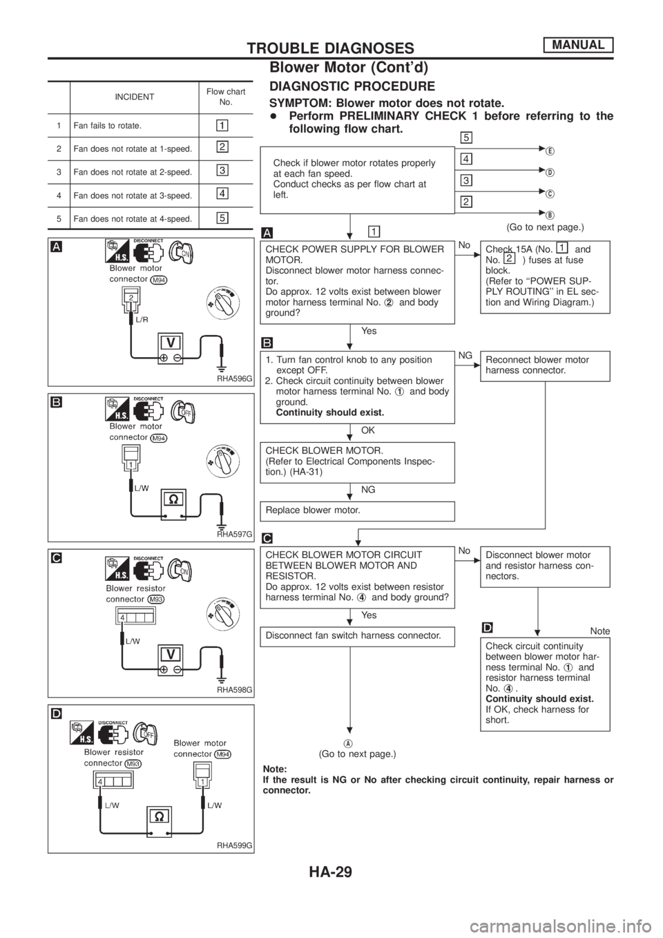
CHECK POWER SUPPLY FOR BLOWER
MOTOR.
Disconnect blower motor harness connec-
tor.
Do approx. 12 volts exist between blower
motor harness terminal No.j
2and body
ground?
Ye s
cNo
Check 15A (No.and
No.) fuses at fuse
block.
(Refer to ``POWER SUP-
PLY ROUTING'' in EL sec-
tion and Wiring Diagram.)
1. Turn fan control knob to any position
except OFF.
2. Check circuit continuity between blower
motor harness terminal No.j
1and body
ground.
Continuity should exist.
OK
cNG
Reconnect blower motor
harness connector.
CHECK BLOWER MOTOR.
(Refer to Electrical Components Inspec-
tion.) (HA-31)
NG
Replace blower motor.
.
CHECK BLOWER MOTOR CIRCUIT
BETWEEN BLOWER MOTOR AND
RESISTOR.
Do approx. 12 volts exist between resistor
harness terminal No.j
4and body ground?
Ye s
cNo
Disconnect blower motor
and resistor harness con-
nectors.
Disconnect fan switch harness connector.Note
Check circuit continuity
between blower motor har-
ness terminal No.j
1and
resistor harness terminal
No.j
4.
Continuity should exist.
If OK, check harness for
short.
jA(Go to next page.)
Note:
If the result is NG or No after checking circuit continuity, repair harness or
connector.
RHA596G
RHA597G
RHA598G
RHA599G
.
.
.
.
..
.
TROUBLE DIAGNOSESMANUAL
Blower Motor (Cont'd)
HA-29
Page 851 of 1226
jA
Note
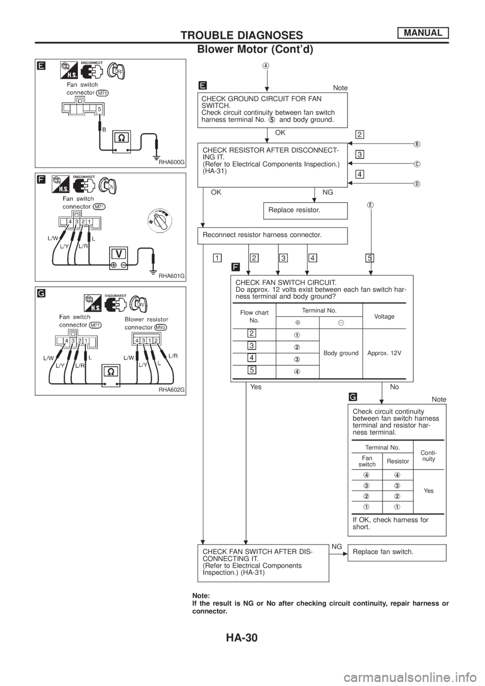
CHECK GROUND CIRCUIT FOR FAN
SWITCH.
Check circuit continuity between fan switch
harness terminal No.j
5and body ground.
OK
CHECK RESISTOR AFTER DISCONNECT-
ING IT.
(Refer to Electrical Components Inspection.)
(HA-31)
OK NG
bjB
bjC
bjD
Replace resistor.jE
Reconnect resistor harness connector.
...
CHECK FAN SWITCH CIRCUIT.
Do approx. 12 volts exist between each fan switch har-
ness terminal and body ground?
Ye s N o
.
Note
Check circuit continuity
between fan switch harness
terminal and resistor har-
ness terminal.
If OK, check harness for
short.
CHECK FAN SWITCH AFTER DIS-
CONNECTING IT.
(Refer to Electrical Components
Inspection.) (HA-31)cNG
Replace fan switch.
Note:
If the result is NG or No after checking circuit continuity, repair harness or
connector.
Flow chart
No.Terminal No.
Voltage
Å@
j1
Body ground Approx. 12Vj2
j3
j4
Terminal No.
Conti-
nuity Fan
switchResistor
j
4j4
Ye s j3j3
j2j2
j1j1
RHA600G
RHA601G
RHA602G
.
.
.
.
.
.
.
TROUBLE DIAGNOSESMANUAL
Blower Motor (Cont'd)
HA-30
Page 950 of 1226

Combination meter........................................EL-102
Combination switch .........................................EL-57
Combustion chamber replacement ................EM-32
Compass .......................................................EL-116
Compression pressure ...................................EM-10
Compressor special service tool ......................HA-6
Connecting rod...............................................EM-47
Connecting rod...............................................EM-51
Connector inspection .......................................GI-17
Console box - See Instrument panel ..............BT-11
Control lever (Transfer) .....................................TF-9
Control sleeve position sensor .......................EC-86
Coolant mixture ratio ......................................MA-11
Coolant replacement ......................................MA-14
Cooling circuit (engine) .....................................LC-9
Cooling fan control .......................................EC-112
Cooling fan motor .........................................EC-120
Cooling fan relay ..........................................EC-120
Cooling fan......................................................LC-15
Counter gear (M/T).........................................MT-10
Counter gear (Transfer) ..................................TF-11
Coupling sleeve (M/T) ....................................MT-10
Crankcase emission control system -
See Positive crankcase ventilation.............EC-21
Crankcase ventilation system - See
Positive crankcase ventilation ....................EC-21
Crankshaft position sensor (TDC)................EC-143
Crankshaft ......................................................EM-50
Cylinder block ..........................................EM-45, 48
Cylinder head .................................................EM-28
D
D/LOCK - Wiring diagram .............................EL-205
DEF - Wiring diagram ...................................EL-159
DEICER - Wiring diagram.............................EL-167
DTRL - Wiring diagram ...................................EL-67
Data link connector for Consult......................EC-36
Daytime light system.......................................EL-65
Diagnosis sensor unit .....................................RS-12
Diagnostic trouble code (DTC) for
ECCS OBD system ....................................EC-30
Differential carrier assembly...........................PD-31
Differential carrier disassembly ......................PD-14
Differential gear oil replacement ....................MA-22
Dimensions ......................................................GI-38
Dome light - See Interior lamp .......................EL-93
Door glass .........................................................BT-9
Door lock ...........................................................BT-9
Door mirror ......................................................BT-46
Door trim .........................................................BT-18
Door, front .........................................................BT-9
Door, rear ........................................................BT-10
Drive belt inspection ......................................MA-12
Drive chain (Transfer) .....................................TF-11
Drive pinion diff. inspection ............................PD-19
Drive pinion height .........................................PD-27
Drive shaft (front) ............................................FA-23
Dual pressure switch ......................................HA-11Dual pressure switch ......................................HA-97
E
ECCS basic inspection...................................EC-46
ECCS circuit diagram .....................................EC-11
ECCS component parts location ......................EC-8
ECCS on board diagnostic system ................EC-30
ECCS symptom matrix chart..........................EC-48
ECCS system diagram and chart ..................EC-12
ECCS-D control module .........................EC-54, 110
ECM input/output signal .................................EC-54
ECTS - Wiring diagram ..................................EC-78
EGR control (EGRC) - solenoid valve .........EC-155
EGR control valve ........................................EC-161
EGRC/V - Wiring diagram ............................EC-155
Electric governor ....................................EC-95, 148
Electric sunroof .............................................EL-186
Electrical diagnoses.........................................GI-20
Electrical unit.................................................EL-321
Electrical units location .................................EL-269
Electronic fuel injection pump ........................EC-27
Engine compartment .......................................BT-49
Engine coolant temperature sensor
(ECTS) ........................................................EC-78
Engine oil ®lter replacement ..........................MA-14
Engine oil precautions .......................................GI-4
Engine oil replacement ..................................MA-13
Engine outer component parts ........................EM-8
Engine removal ..............................................EM-43
Engine room - See Engine
compartment ...............................................BT-49
Engine serial number ......................................GI-37
Exhaust system inspection ............................MA-20
Exhaust system ................................................FE-3
Exterior ............................................................BT-26
F
FCUT - Wiring diagram ................................EC-129
FTS - Wiring diagram ...................................EC-134
Fan control amp. ............................................HA-88
Final drive disassembly ..................................PD-14
Final drive removal and installation................PD-11
Finisher, interior - See Trim ............................BT-14
Floor trim .........................................................BT-14
Flow charts ......................................................GI-30
Fluids................................................................MA-9
Flywheel (clutch).......................................CL-13, 14
Flywheel runout..............................................EM-52
Fog lamp, rear ................................................EL-80
Fork rod (M/T) ................................................MT-12
Front axle ........................................................FA-10
Front bumper ....................................................BT-4
Front case (Transfer) ......................................TF-10
Front disc brake .............................................BR-20
Front door .........................................................BT-9
ALPHABETICAL INDEX
IDX-3
Page 951 of 1226

Front drive shaft (Transfer) .............................TF-11
Front ®nal drive disassembly (4WD) ..............PD-14
Front ®nal drive removal and installa-
tion (4WD)...................................................PD-11
Front passenger air bag.............................RS-8, 14
Front seat belt ..................................................RS-2
Front seat ........................................................BT-32
Front suspension ............................................FA-24
Front washer .................................................EL-141
Front wiper ....................................................EL-141
Fuel cut control (at no load & high
engine speed) .............................................EC-20
Fuel cut solenoid valve ................................EC-129
Fuel ®ller lid.......................................................BT-6
Fuel ®lter replacement ...................................MA-16
Fuel gauge ....................................................EL-102
Fuel injection system......................................EC-15
Fuel line inspection ........................................MA-17
Fuel precautions ................................................GI-5
Fuel temperature sensor ..............................EC-134
Fuse block.....................................................EL-319
Fuse ................................................................EL-14
Fusible link ......................................................EL-14
G
GLOW - Wiring diagram...............................EC-150
GOVNR - Wiring diagram ..............................EC-95
Garage jack and safety stand .........................GI-39
Gauges..........................................................EL-102
Gear components (M/T) .................................MT-10
Glass .................................................................BT-9
Glow plug .............................................EC-150, 154
Glow relay ............................................EC-150, 154
Grease .............................................................MA-9
Ground distribution..........................................EL-15
H
H/AIM - Wiring diagram ..................................EL-71
H/LAMP - Wiring diagram ...............................EL-61
HEAT UP - Wiring diagram ..........................EC-182
HFC134a (R134a) system service
procedure ..................................................HA-112
HLC - Wiring diagram ...................................EL-153
HORN - Wiring diagram................................EL-155
Harness connector inspection .........................GI-17
Harness connector ............................................EL-2
Harness layout ..............................................EL-275
Headlamp aiming control ................................EL-70
Headlamp leveler - See Headlamp
aiming control ..............................................EL-70
Headlamp wiper ............................................EL-153
Headlamp ........................................................EL-61
Headlining - See Roof trim .............................BT-20
Heat up switch..............................................EC-182
Heated seat.....................................................BT-34Hood..................................................................BT-4
Horn ..............................................................EL-155
How to erase DTC for ECCS OBD
system ........................................................EC-30
I
IATS - Wiring diagram ..................................EC-121
IC/FAN - Wiring diagram ..............................EC-177
ILL - Wiring diagram .......................................EL-87
INT/L - Wiring diagram..................................EL-101
Identi®cation plate............................................GI-37
Idle speed inspection .....................................MA-19
Idle speed .......................................................EC-46
Illumination ......................................................EL-86
In vehicle sensor ..........................................HA-105
Injection nozzle inspection .............................MA-18
Injection nozzle...............................................EC-22
Injection timing control valve ........................EC-100
Instrument panel .............................................BT-11
Intake door control linkage adjustment ..........HA-84
Intake door motor ...........................................HA-25
Intake sensor ................................................HA-111
Interior lamp ....................................................EL-93
Interior .............................................................BT-14
J
Jacking points ..................................................GI-39
Joint connector (J/C).....................................EL-322
Journal bearing assembly (propeller
shaft) .............................................................PD-8
Journal bearing disassembly (propeller
shaft) .............................................................PD-7
Junction box (J/B) .........................................EL-319
L
LSV (Load sensing valve) ................................BR-6
Lifting points ....................................................GI-40
Limited slip diff. adjustment............................PD-23
Limited slip diff. assembly ..............................PD-24
Limited slip diff. disassembly .........................PD-21
Limited slip diff. inspection .............................PD-21
Location of electrical units ............................EL-269
Lock, door .........................................................BT-9
Lubricant (R134a) A/C ..................................HA-114
Lubricants.........................................................MA-9
Lubrication circuit (engine) ...............................LC-3
Lubrication-locks, hinges and hood
latches ........................................................MA-27
Luggage compartment trim .............................BT-14
Luggage room lamp ........................................EL-93
ALPHABETICAL INDEX
IDX-4
Page 978 of 1226
Supplemental Restraint System (SRS) ``AIR
BAG'' and ``SEAT BELT PRE-TENSIONER''
The Supplemental Restraint System such as ``AIR BAG'' and ``SEAT BELT PRE-TENSIONER'' used along with
a seat belt, helps to reduce the risk or severity of injury to the driver and front passenger in a frontal collision.
The SRS composition which is available to NISSAN MODEL Y61 is as follows (The composition varies
according to the destination.):
Driver air bag module (located in the center of the steering wheel), front passenger air bag module (located
on the instrument panel on passenger side), seat belt pre-tensioner, a diagnosis sensor unit, warning lamp,
wiring harness and spiral cable.
WARNING:
+To avoid rendering the SRS inoperative, which could increase the risk of personal injury or death
in the event of a collision which would result in air bag in¯ation, all maintenance must be performed
by an authorized NISSAN dealer.
+Improper maintenance, including incorrect removal and installation of the SRS, can lead to per-
sonal injury caused by unintentional activation of the system.
+Do not use electrical test equipment on any circuit related to the SRS unless instructed to in this
Service Manual. Spiral cable and wiring harnesses covered with yellow insulation either just before
the harness connectors or for the complete harness are related to the SRS.
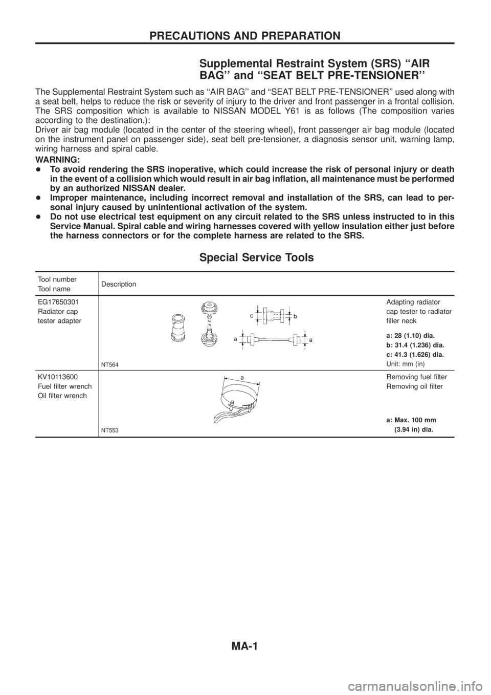
Special Service Tools
Tool number
Tool nameDescription
EG17650301
Radiator cap
tester adapter
NT564
Adapting radiator
cap tester to radiator
®ller neck
a: 28 (1.10) dia.
b: 31.4 (1.236) dia.
c: 41.3 (1.626) dia.
Unit: mm (in)
KV10113600
Fuel ®lter wrench
Oil ®lter wrench
NT553
Removing fuel ®lter
Removing oil ®lter
a: Max. 100 mm
(3.94 in) dia.
PRECAUTIONS AND PREPARATION
MA-1
Page 1122 of 1226
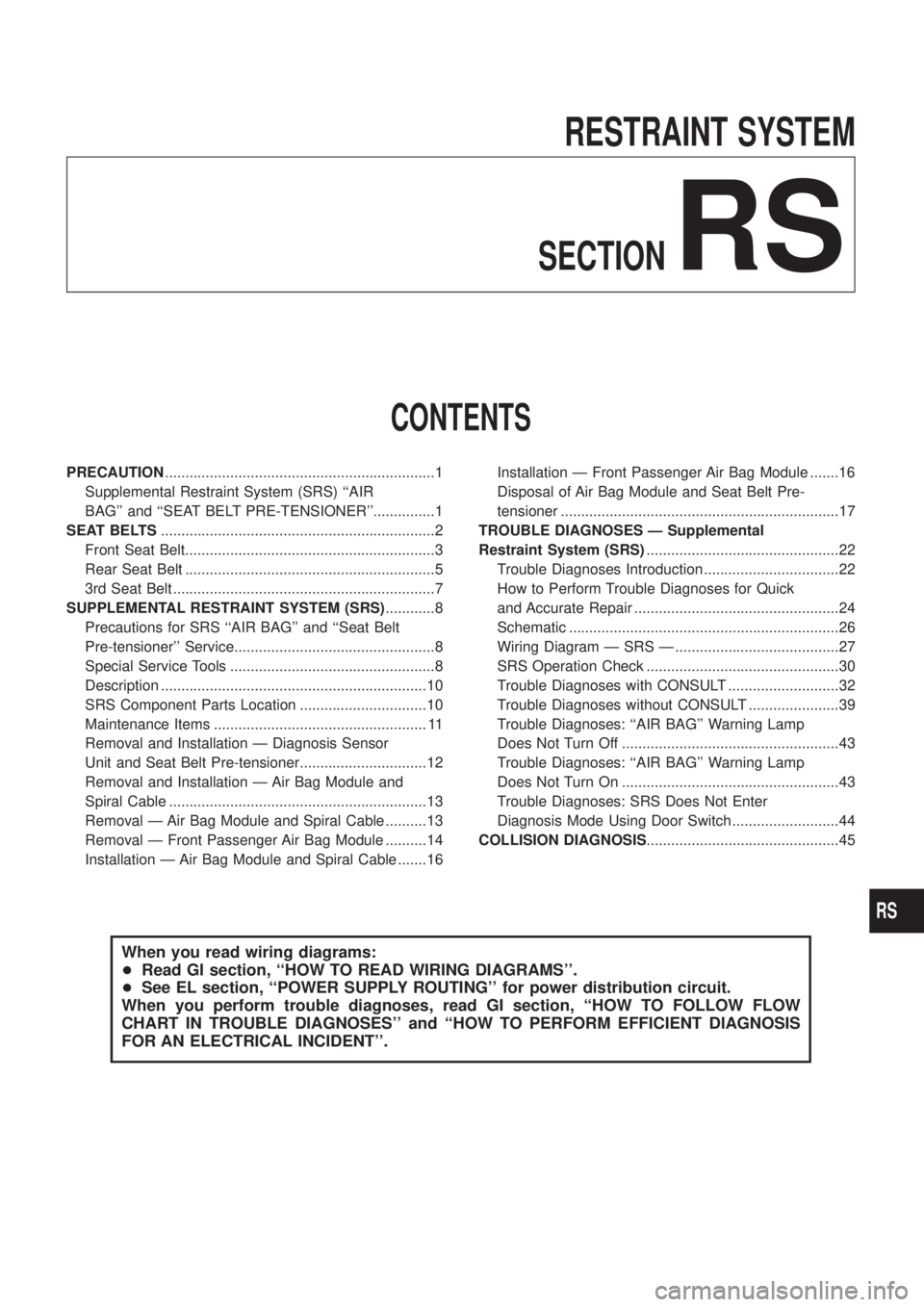
RESTRAINT SYSTEM
SECTION
RS
CONTENTS
PRECAUTION..................................................................1
Supplemental Restraint System (SRS) ``AIR
BAG'' and ``SEAT BELT PRE-TENSIONER''...............1
SEAT BELTS...................................................................2
Front Seat Belt.............................................................3
Rear Seat Belt .............................................................5
3rd Seat Belt ................................................................7
SUPPLEMENTAL RESTRAINT SYSTEM (SRS)............8
Precautions for SRS ``AIR BAG'' and ``Seat Belt
Pre-tensioner'' Service.................................................8
Special Service Tools ..................................................8
Description .................................................................10
SRS Component Parts Location ...............................10
Maintenance Items .................................................... 11
Removal and Installation Ð Diagnosis Sensor
Unit and Seat Belt Pre-tensioner...............................12
Removal and Installation Ð Air Bag Module and
Spiral Cable ...............................................................13
Removal Ð Air Bag Module and Spiral Cable ..........13
Removal Ð Front Passenger Air Bag Module ..........14
Installation Ð Air Bag Module and Spiral Cable .......16Installation Ð Front Passenger Air Bag Module .......16
Disposal of Air Bag Module and Seat Belt Pre-
tensioner ....................................................................17
TROUBLE DIAGNOSES Ð Supplemental
Restraint System (SRS)...............................................22
Trouble Diagnoses Introduction.................................22
How to Perform Trouble Diagnoses for Quick
and Accurate Repair ..................................................24
Schematic ..................................................................26
Wiring Diagram Ð SRS Ð ........................................27
SRS Operation Check ...............................................30
Trouble Diagnoses with CONSULT ...........................32
Trouble Diagnoses without CONSULT ......................39
Trouble Diagnoses: ``AIR BAG'' Warning Lamp
Does Not Turn Off .....................................................43
Trouble Diagnoses: ``AIR BAG'' Warning Lamp
Does Not Turn On .....................................................43
Trouble Diagnoses: SRS Does Not Enter
Diagnosis Mode Using Door Switch ..........................44
COLLISION DIAGNOSIS...............................................45
When you read wiring diagrams:
+Read GI section, ``HOW TO READ WIRING DIAGRAMS''.
+See EL section, ``POWER SUPPLY ROUTING'' for power distribution circuit.
When you perform trouble diagnoses, read GI section, ``HOW TO FOLLOW FLOW
CHART IN TROUBLE DIAGNOSES'' and ``HOW TO PERFORM EFFICIENT DIAGNOSIS
FOR AN ELECTRICAL INCIDENT''.
RS