Page 1116 of 1226
Trouble Diagnoses
DIAGNOSTIC PROCEDURE 1
(POWER SUPPLY AND GROUND CIRCUIT CHECK)
CHECK POWER SUPPLY CIRCUIT FOR
STABILIZER CONTROL UNIT.
1. Turn ignition switch ON.
2. Check voltage between control unit
connector terminals
V4,V5and
ground.
Battery voltage should exist.
OK
cNG
Check the following.
+7.5A fuse
24, 10A fuse
28
+Harness connectorM44
+Harness for open or
short between control
unit and fuse
If NG, repair fuse, harness
or connectors.
CHECK GROUND CIRCUIT FOR STABI-
LIZER CONTROL UNIT.
1. Disconnect control unit connector.
2. Check continuity between control unit
connector terminal
V10and ground.
Continuity should exist.
OK
cNG
Check the following.
+Harness connector
M44
+Harness for open or
short between control
unit and ground
If NG, repair harness or
connectors.
Power supply and ground circuit is OK.
SRA838A
SRA839A
.
.
STABILIZER RELEASE DEVICE
RA-20
Page 1118 of 1226

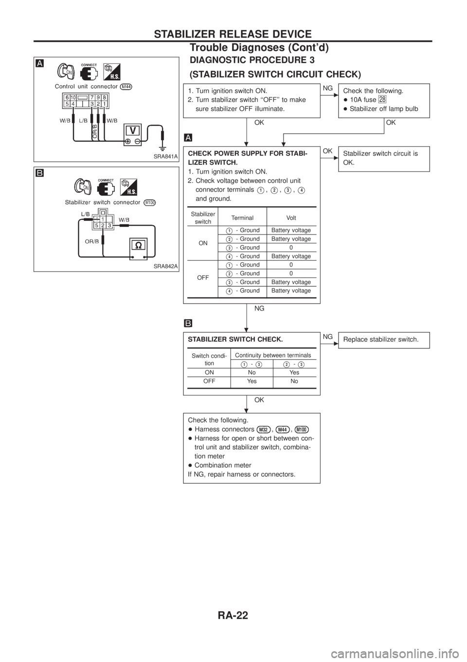
DIAGNOSTIC PROCEDURE 3
(STABILIZER SWITCH CIRCUIT CHECK)
1. Turn ignition switch ON.
2. Turn stabilizer switch ``OFF'' to make
sure stabilizer OFF illuminate.
OK
cNG
Check the following.
+10A fuse
28
+Stabilizer off lamp bulb
OK
.
CHECK POWER SUPPLY FOR STABI-
LIZER SWITCH.
1. Turn ignition switch ON.
2. Check voltage between control unit
connector terminals
V1,V2,V3,V4
and ground.
NG
cOK
Stabilizer switch circuit is
OK.
STABILIZER SWITCH CHECK.
OK
cNG
Replace stabilizer switch.
Check the following.
+Harness connectors
M32,M44,M100
+Harness for open or short between con-
trol unit and stabilizer switch, combina-
tion meter
+Combination meter
If NG, repair harness or connectors.
Stabilizer
switchTerminal Volt
ON
V1- Ground Battery voltage
V2- Ground Battery voltage
V3- Ground 0
V4- Ground Battery voltage
OFF
V1- Ground 0
V2- Ground 0
V3- Ground Battery voltage
V4- Ground Battery voltage
Switch condi-
tionContinuity between terminals
V1-V3V2-V3
ON No Yes
OFF Yes No
SRA841A
SRA842A
.
.
.
STABILIZER RELEASE DEVICE
Trouble Diagnoses (Cont'd)
RA-22
Page 1146 of 1226
![NISSAN PATROL 2006 Service Manual HOW TO ERASE SELF-DIAGNOSIS RESULTS
With CONSULT
+``SELF-DIAG [CURRENT]
A current Self-diagnosis result is displayed on the CONSULT screen in real time. After the malfunction is
repaired completely, NISSAN PATROL 2006 Service Manual HOW TO ERASE SELF-DIAGNOSIS RESULTS
With CONSULT
+``SELF-DIAG [CURRENT]
A current Self-diagnosis result is displayed on the CONSULT screen in real time. After the malfunction is
repaired completely,](/manual-img/5/57368/w960_57368-1145.png)
HOW TO ERASE SELF-DIAGNOSIS RESULTS
With CONSULT
+``SELF-DIAG [CURRENT]''
A current Self-diagnosis result is displayed on the CONSULT screen in real time. After the malfunction is
repaired completely, no malfunction is detected on ``SELF-DIAG [CURRENT]''.
+``SELF-DIAG [PAST]''
Return to the ``SELF-DIAG [CURRENT]'' CONSULT screen by
pushing ``BACK'' key of CONSULT and select ``SELF-DIAG
[CURRENT]'' in ``SELECT DIAG MODE''. Touch ``ERASE'' in
``SELF-DIAG [CURRENT]'' mode.
NOTE:
If the memory of the malfunction in ``SELF-DIAG [PAST]'' is not
erased, the User mode shows the system malfunction by the
operation of the warning lamp even if the malfunction is
repaired completely.
+``TROUBLE DIAG RECORD''
The memory of ``TROUBLE DIAG RECORD'' cannot be erased.
Without CONSULT
After a malfunction is repaired, return to User mode from Diagnosis mode by switching the ignition ``OFF'' for
at least 1 second, then back ``ON''. At that time, the problem code is cleared.
How to Perform Trouble Diagnoses for Quick
and Accurate Repair
A good understanding of the malfunction conditions can make troubleshooting faster and more accurate.
In general, each customer feels differently about a problem. It is important to fully understand the symptoms
or conditions for a customer complaint.
INFORMATION FROM CUSTOMER
WHAT ............ Vehicle model
WHEN ........... Date, Frequencies
WHERE ......... Road conditions
HOW .............. Operating conditions, Symptoms
PRELIMINARY CHECK
Check that the following parts are in good order.
+Battery [Refer to EL section (``BATTERY'').]
+Fuse [Refer to EL section (``Fuse'', ``POWER SUPPLY ROUTING'').]
+System component-to-harness connections
SRS357
TROUBLE DIAGNOSES Ð Supplemental Restraint System (SRS)
Trouble Diagnoses Introduction (Cont'd)
RS-24
Page 1152 of 1226

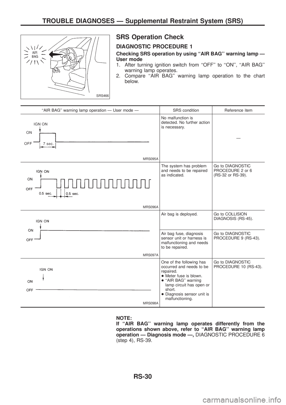
SRS Operation Check
DIAGNOSTIC PROCEDURE 1
Checking SRS operation by using ``AIR BAG'' warning lamp Ð
User mode
1. After turning ignition switch from ``OFF'' to ``ON'', ``AIR BAG''
warning lamp operates.
2. Compare ``AIR BAG'' warning lamp operation to the chart
below.
``AIR BAG'' warning lamp operation Ð User mode Ð SRS condition Reference item
MRS095A
No malfunction is
detected. No further action
is necessary.
Ð
MRS096A
The system has problem
and needs to be repaired
as indicated.Go to DIAGNOSTIC
PROCEDURE 2 or 6
(RS-32 or RS-39).
MRS097A
Air bag is deployed. Go to COLLISION
DIAGNOSIS (RS-45).
Air bag fuse, diagnosis
sensor unit or harness is
malfunctioning and needs
to be repaired.Go to DIAGNOSTIC
PROCEDURE 9 (RS-43).
MRS098A
One of the following has
occurred and needs to be
repaired.
+Meter fuse is blown.
+``AIR BAG'' warning
lamp circuit has open or
short.
+Diagnosis sensor unit is
malfunctioning.Go to DIAGNOSTIC
PROCEDURE 10 (RS-43).
NOTE:
If ``AIR BAG'' warning lamp operates differently from the
operations shown above, refer to ``AIR BAG'' warning lamp
operation Ð Diagnosis mode Ð,DIAGNOSTIC PROCEDURE 6
(step 4), RS-39.
SRS466
TROUBLE DIAGNOSES Ð Supplemental Restraint System (SRS)
RS-30
Page 1164 of 1226

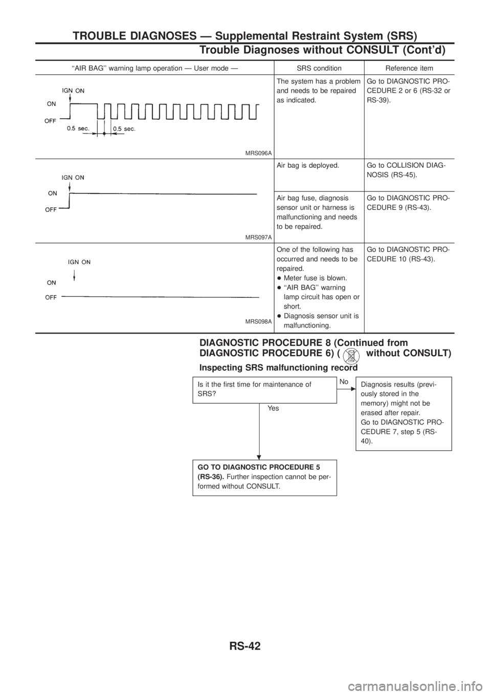
``AIR BAG'' warning lamp operation Ð User mode Ð SRS condition Reference item
MRS096A
The system has a problem
and needs to be repaired
as indicated.Go to DIAGNOSTIC PRO-
CEDURE 2 or 6 (RS-32 or
RS-39).
MRS097A
Air bag is deployed. Go to COLLISION DIAG-
NOSIS (RS-45).
Air bag fuse, diagnosis
sensor unit or harness is
malfunctioning and needs
to be repaired.Go to DIAGNOSTIC PRO-
CEDURE 9 (RS-43).
MRS098A
One of the following has
occurred and needs to be
repaired.
+Meter fuse is blown.
+``AIR BAG'' warning
lamp circuit has open or
short.
+Diagnosis sensor unit is
malfunctioning.Go to DIAGNOSTIC PRO-
CEDURE 10 (RS-43).
DIAGNOSTIC PROCEDURE 8 (Continued from
DIAGNOSTIC PROCEDURE 6) (
without CONSULT)
Inspecting SRS malfunctioning record
Is it the ®rst time for maintenance of
SRS?
Ye s
cNo
Diagnosis results (previ-
ously stored in the
memory) might not be
erased after repair.
Go to DIAGNOSTIC PRO-
CEDURE 7, step 5 (RS-
40).
GO TO DIAGNOSTIC PROCEDURE 5
(RS-36).Further inspection cannot be per-
formed without CONSULT.
.
TROUBLE DIAGNOSES Ð Supplemental Restraint System (SRS)
Trouble Diagnoses without CONSULT (Cont'd)
RS-42
Page 1165 of 1226

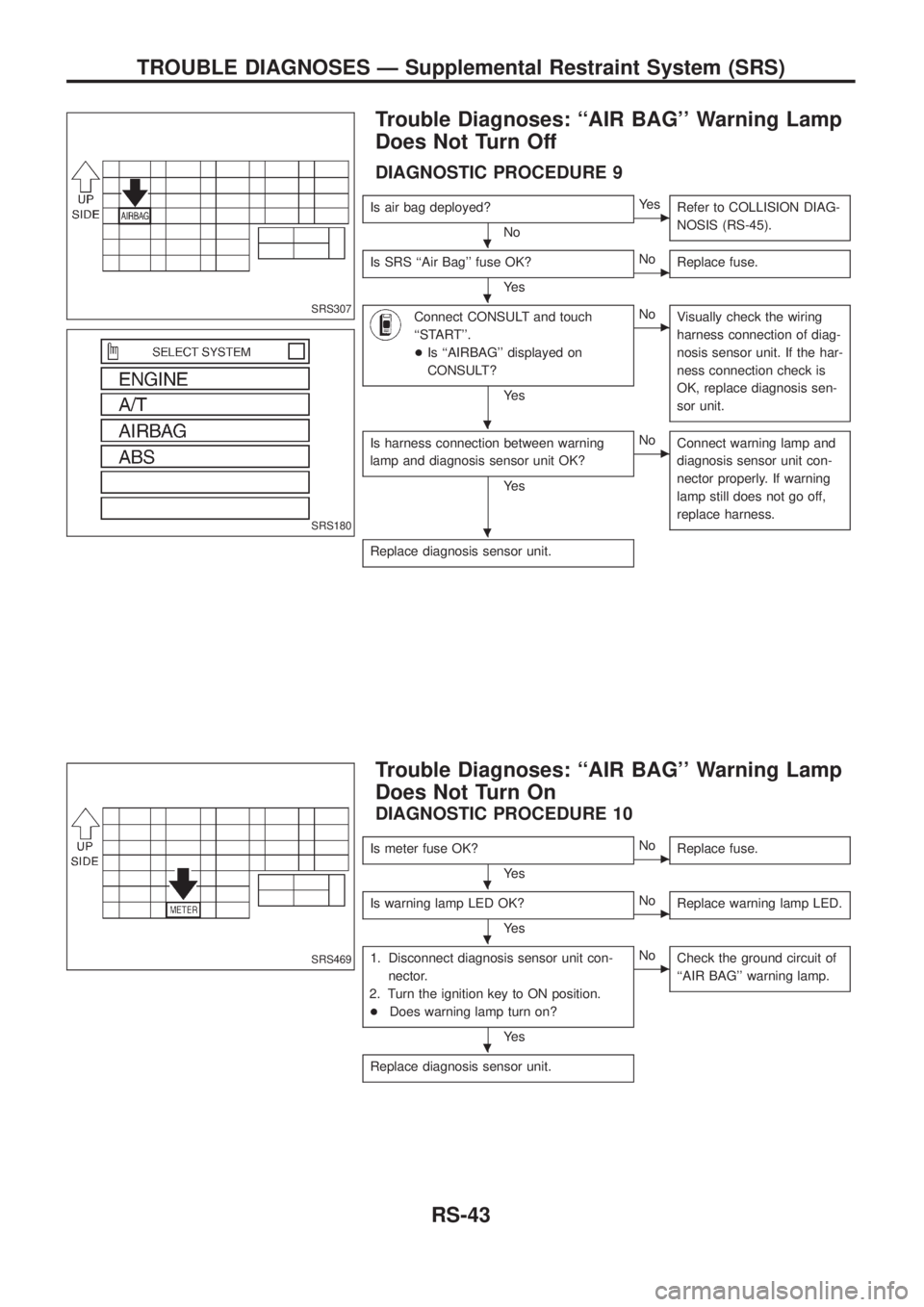
Trouble Diagnoses: ``AIR BAG'' Warning Lamp
Does Not Turn Off
DIAGNOSTIC PROCEDURE 9
Is air bag deployed?
NocYe s
Refer to COLLISION DIAG-
NOSIS (RS-45).
Is SRS ``Air Bag'' fuse OK?
Ye scNo
Replace fuse.
Connect CONSULT and touch
``START''.
+Is ``AIRBAG'' displayed on
CONSULT?
Ye s
cNo
Visually check the wiring
harness connection of diag-
nosis sensor unit. If the har-
ness connection check is
OK, replace diagnosis sen-
sor unit.
Is harness connection between warning
lamp and diagnosis sensor unit OK?
Ye s
cNo
Connect warning lamp and
diagnosis sensor unit con-
nector properly. If warning
lamp still does not go off,
replace harness.
Replace diagnosis sensor unit.
Trouble Diagnoses: ``AIR BAG'' Warning Lamp
Does Not Turn On
DIAGNOSTIC PROCEDURE 10
Is meter fuse OK?
Ye scNo
Replace fuse.
Is warning lamp LED OK?
Ye scNo
Replace warning lamp LED.
1. Disconnect diagnosis sensor unit con-
nector.
2. Turn the ignition key to ON position.
+Does warning lamp turn on?
Ye s
cNo
Check the ground circuit of
``AIR BAG'' warning lamp.
Replace diagnosis sensor unit.
SRS307
SRS180
SRS469
.
.
.
.
.
.
.
TROUBLE DIAGNOSES Ð Supplemental Restraint System (SRS)
RS-43