2006 NISSAN PATROL fuse
[x] Cancel search: fusePage 906 of 1226
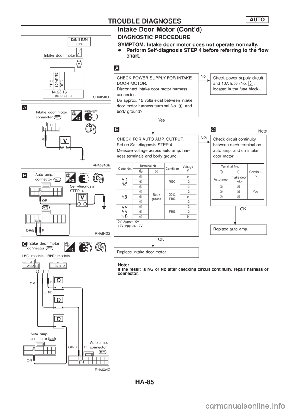
DIAGNOSTIC PROCEDURE
SYMPTOM: Intake door motor does not operate normally.
+Perform Self-diagnosis STEP 4 before referring to the ¯ow
chart.
CHECK POWER SUPPLY FOR INTAKE
DOOR MOTOR.
Disconnect intake door motor harness
connector.
Do approx. 12 volts exist between intake
door motor harness terminal No.j
1and
body ground?
Ye s
cNo
Check power supply circuit
and 10A fuse (No.
6,
located in the fuse block).
Note
CHECK FOR AUTO AMP. OUTPUT.
Set up Self-diagnosis STEP 4.
Measure voltage across auto amp. har-
ness terminals and body ground.
OK
cNG
Check circuit continuity
between each terminal on
auto amp. and on intake
door motor.
OK
Replace auto amp.
Replace intake door motor.
Note:If the result is NG or No after checking circuit continuity, repair harness or
connector.
Code No.Terminal No.
ConditionVoltage
VÅ@
j13
Body
groundREC0
j
2312
j
1412j1320%
FRE12
j230
j
1412j13
FRE12
j2312
j
140
0V: Approx. 0V
12V: Approx. 12V
Terminal No.
Continu-
ityÅ@
Auto amp.Intake door
motor
j
13j13
Ye s j23j23j14j14
SHA858EB
RHA081GB
RHA642G
RHA634G
.
.
.
TROUBLE DIAGNOSESAUTO
Intake Door Motor (Cont'd)
HA-85
Page 910 of 1226
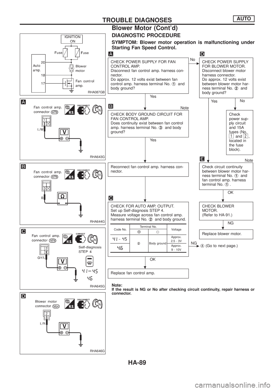
DIAGNOSTIC PROCEDURE
SYMPTOM: Blower motor operation is malfunctioning under
Starting Fan Speed Control.
CHECK POWER SUPPLY FOR FAN
CONTROL AMP.
Disconnect fan control amp. harness con-
nector.
Do approx. 12 volts exist between fan
control amp. harness terminal No.j
1and
body ground?
Ye s
cNo
CHECK POWER SUPPLY
FOR BLOWER MOTOR.
Disconnect blower motor
harness connector.
Do approx. 12 volts exist
between blower motor har-
ness terminal No.j
2and
body ground?
No
.
Ye s
Note
CHECK BODY GROUND CIRCUIT FOR
FAN CONTROL AMP.
Does continuity exist between fan control
amp. harness terminal No.j
3and body
ground?
Ye sCheck
power sup-
ply circuit
and 15A
fuses (No.1and2,
located in
the fuse
block).
Note
Reconnect fan control amp. harness con-
nector.
Check circuit continuity
between blower motor har-
ness terminal No.j
1and
fan control amp. harness
terminal No.j
1.
OK
CHECK FOR AUTO AMP. OUTPUT.
Set up Self-diagnosis STEP 4.
Measure voltage across fan control amp.
harness terminal No.j
2and body ground.
OKCHECK BLOWER
MOTOR.
(Refer to HA-91.)
NG
Replace blower motor.
cNG
jA(Go to next page.)
Replace fan control amp.
Note:If the result is NG or No after checking circuit continuity, repair harness or
connector.
Code No.Terminal No.
VoltageÅ@
þj2Body groundApprox.
2.5-3VApprox.
9 - 10V
RHA087GB
RHA643G
RHA644G
RHA645G
RHA646G
..
.
..
.
.
TROUBLE DIAGNOSESAUTO
Blower Motor (Cont'd)
HA-89
Page 911 of 1226
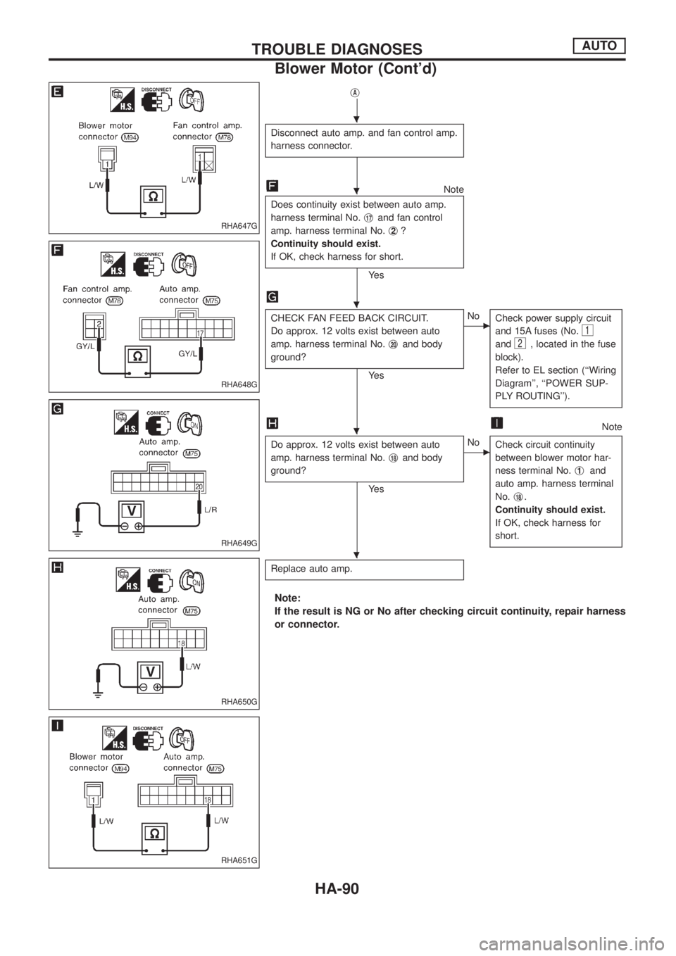
jA
Disconnect auto amp. and fan control amp.
harness connector.
Note
Does continuity exist between auto amp.
harness terminal No.j
17and fan control
amp. harness terminal No.j
2?
Continuity should exist.
If OK, check harness for short.
Ye s
CHECK FAN FEED BACK CIRCUIT.
Do approx. 12 volts exist between auto
amp. harness terminal No.j
20and body
ground?
Ye s
cNo
Check power supply circuit
and 15A fuses (No.
1
and2, located in the fuse
block).
Refer to EL section (``Wiring
Diagram'', ``POWER SUP-
PLY ROUTING'').
Note
Do approx. 12 volts exist between auto
amp. harness terminal No.j
18and body
ground?
Ye s
cNo
Check circuit continuity
between blower motor har-
ness terminal No.j
1and
auto amp. harness terminal
No.j
18.
Continuity should exist.
If OK, check harness for
short.
Replace auto amp.
Note:
If the result is NG or No after checking circuit continuity, repair harness
or connector.
RHA647G
RHA648G
RHA649G
RHA650G
RHA651G
.
.
.
.
.
TROUBLE DIAGNOSESAUTO
Blower Motor (Cont'd)
HA-90
Page 915 of 1226
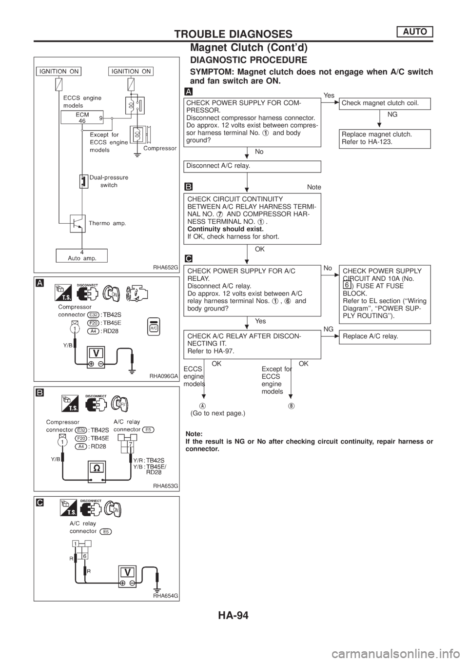
DIAGNOSTIC PROCEDURE
SYMPTOM: Magnet clutch does not engage when A/C switch
and fan switch are ON.
CHECK POWER SUPPLY FOR COM-
PRESSOR.
Disconnect compressor harness connector.
Do approx. 12 volts exist between compres-
sor harness terminal No.j
1and body
ground?
No
cYe s
Check magnet clutch coil.
NG
Replace magnet clutch.
Refer to HA-123.
Disconnect A/C relay.
Note
CHECK CIRCUIT CONTINUITY
BETWEEN A/C RELAY HARNESS TERMI-
NAL NO.j
7AND COMPRESSOR HAR-
NESS TERMINAL NO.j1.
Continuity should exist.
If OK, check harness for short.
OK
CHECK POWER SUPPLY FOR A/C
RELAY.
Disconnect A/C relay.
Do approx. 12 volts exist between A/C
relay harness terminal Nos.j
1,j6and
body ground?
Ye s
cNo
CHECK POWER SUPPLY
CIRCUIT AND 10A (No.
) FUSE AT FUSE
BLOCK.
Refer to EL section (``Wiring
Diagram'', ``POWER SUP-
PLY ROUTING'').
CHECK A/C RELAY AFTER DISCON-
NECTING IT.
Refer to HA-97.
OK OK
ECCS
engine
modelsExcept for
ECCS
engine
models
cNG
Replace A/C relay.
jA(Go to next page.)jB
Note:
If the result is NG or No after checking circuit continuity, repair harness or
connector.
RHA652G
RHA096GA
RHA653G
RHA654G
.
.
.
.
.
..
TROUBLE DIAGNOSESAUTO
Magnet Clutch (Cont'd)
HA-94
Page 917 of 1226
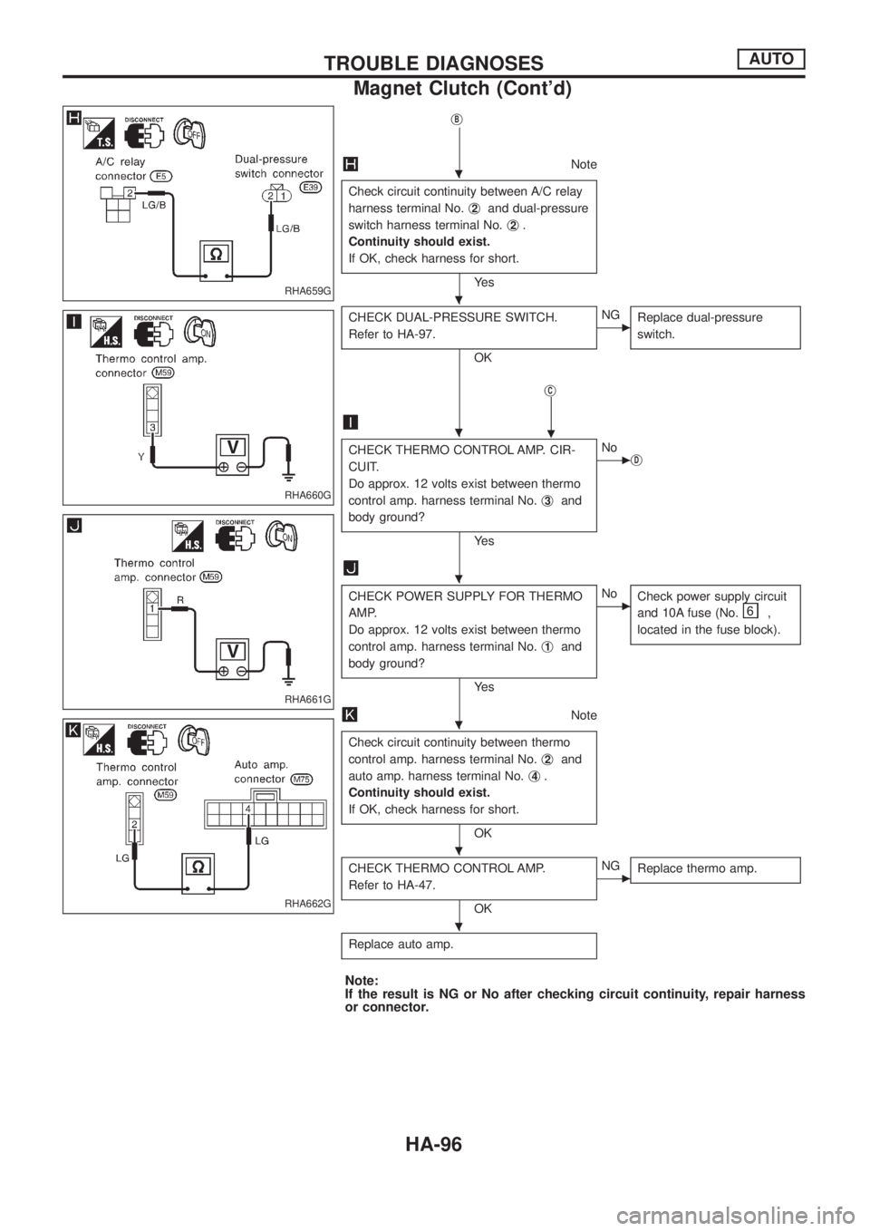
jB
Note
Check circuit continuity between A/C relay
harness terminal No.j
2and dual-pressure
switch harness terminal No.j
2.
Continuity should exist.
If OK, check harness for short.
Ye s
CHECK DUAL-PRESSURE SWITCH.
Refer to HA-97.
OK
cNG
Replace dual-pressure
switch.
jC
.
CHECK THERMO CONTROL AMP. CIR-
CUIT.
Do approx. 12 volts exist between thermo
control amp. harness terminal No.j
3and
body ground?
Ye s
cNo
jD
CHECK POWER SUPPLY FOR THERMO
AMP.
Do approx. 12 volts exist between thermo
control amp. harness terminal No.j
1and
body ground?
Ye s
cNo
Check power supply circuit
and 10A fuse (No.
,
located in the fuse block).
Note
Check circuit continuity between thermo
control amp. harness terminal No.j
2and
auto amp. harness terminal No.j
4.
Continuity should exist.
If OK, check harness for short.
OK
CHECK THERMO CONTROL AMP.
Refer to HA-47.
OK
cNG
Replace thermo amp.
Replace auto amp.
Note:
If the result is NG or No after checking circuit continuity, repair harness
or connector.
RHA659G
RHA660G
RHA661G
RHA662G
.
.
.
.
.
.
.
TROUBLE DIAGNOSESAUTO
Magnet Clutch (Cont'd)
HA-96
Page 951 of 1226

Front drive shaft (Transfer) .............................TF-11
Front ®nal drive disassembly (4WD) ..............PD-14
Front ®nal drive removal and installa-
tion (4WD)...................................................PD-11
Front passenger air bag.............................RS-8, 14
Front seat belt ..................................................RS-2
Front seat ........................................................BT-32
Front suspension ............................................FA-24
Front washer .................................................EL-141
Front wiper ....................................................EL-141
Fuel cut control (at no load & high
engine speed) .............................................EC-20
Fuel cut solenoid valve ................................EC-129
Fuel ®ller lid.......................................................BT-6
Fuel ®lter replacement ...................................MA-16
Fuel gauge ....................................................EL-102
Fuel injection system......................................EC-15
Fuel line inspection ........................................MA-17
Fuel precautions ................................................GI-5
Fuel temperature sensor ..............................EC-134
Fuse block.....................................................EL-319
Fuse ................................................................EL-14
Fusible link ......................................................EL-14
G
GLOW - Wiring diagram...............................EC-150
GOVNR - Wiring diagram ..............................EC-95
Garage jack and safety stand .........................GI-39
Gauges..........................................................EL-102
Gear components (M/T) .................................MT-10
Glass .................................................................BT-9
Glow plug .............................................EC-150, 154
Glow relay ............................................EC-150, 154
Grease .............................................................MA-9
Ground distribution..........................................EL-15
H
H/AIM - Wiring diagram ..................................EL-71
H/LAMP - Wiring diagram ...............................EL-61
HEAT UP - Wiring diagram ..........................EC-182
HFC134a (R134a) system service
procedure ..................................................HA-112
HLC - Wiring diagram ...................................EL-153
HORN - Wiring diagram................................EL-155
Harness connector inspection .........................GI-17
Harness connector ............................................EL-2
Harness layout ..............................................EL-275
Headlamp aiming control ................................EL-70
Headlamp leveler - See Headlamp
aiming control ..............................................EL-70
Headlamp wiper ............................................EL-153
Headlamp ........................................................EL-61
Headlining - See Roof trim .............................BT-20
Heat up switch..............................................EC-182
Heated seat.....................................................BT-34Hood..................................................................BT-4
Horn ..............................................................EL-155
How to erase DTC for ECCS OBD
system ........................................................EC-30
I
IATS - Wiring diagram ..................................EC-121
IC/FAN - Wiring diagram ..............................EC-177
ILL - Wiring diagram .......................................EL-87
INT/L - Wiring diagram..................................EL-101
Identi®cation plate............................................GI-37
Idle speed inspection .....................................MA-19
Idle speed .......................................................EC-46
Illumination ......................................................EL-86
In vehicle sensor ..........................................HA-105
Injection nozzle inspection .............................MA-18
Injection nozzle...............................................EC-22
Injection timing control valve ........................EC-100
Instrument panel .............................................BT-11
Intake door control linkage adjustment ..........HA-84
Intake door motor ...........................................HA-25
Intake sensor ................................................HA-111
Interior lamp ....................................................EL-93
Interior .............................................................BT-14
J
Jacking points ..................................................GI-39
Joint connector (J/C).....................................EL-322
Journal bearing assembly (propeller
shaft) .............................................................PD-8
Journal bearing disassembly (propeller
shaft) .............................................................PD-7
Junction box (J/B) .........................................EL-319
L
LSV (Load sensing valve) ................................BR-6
Lifting points ....................................................GI-40
Limited slip diff. adjustment............................PD-23
Limited slip diff. assembly ..............................PD-24
Limited slip diff. disassembly .........................PD-21
Limited slip diff. inspection .............................PD-21
Location of electrical units ............................EL-269
Lock, door .........................................................BT-9
Lubricant (R134a) A/C ..................................HA-114
Lubricants.........................................................MA-9
Lubrication circuit (engine) ...............................LC-3
Lubrication-locks, hinges and hood
latches ........................................................MA-27
Luggage compartment trim .............................BT-14
Luggage room lamp ........................................EL-93
ALPHABETICAL INDEX
IDX-4
Page 979 of 1226
Shown below are Pre-delivery Inspection Items required for the new vehicle. It is recommended that
necessary items other than those listed here be added, paying due regard to the conditions in each
country.
Perform applicable items on each model. Consult text of this section for speci®cations.
UNDER HOOD Ð engine off
hRadiator coolant level and coolant hose connec-
tions for leaks
hBattery ¯uid level, speci®c gravity and condi-
tions of battery terminals
hDrive belts tension
hFuel ®lter for water or dusts, and fuel lines and
connections for leaks
hEngine oil level and oil leaks
hClutch and brake reservoir ¯uid level and ¯uid
lines for leaks
hWindshield and rear window washer and head-
lamp cleaner reservoir ¯uid level
hPower steering reservoir ¯uid level and hose
connections for leaks
ON INSIDE AND OUTSIDE
hXRemove front spring/strut spacer (If applicable)
hOperation of all instruments, gauges, lights and
accessories
hOperation of horn(s), wiper and washer
hSteering lock for operation
hCheck air conditioner for gas leaks
hFront and rear seats, and seat belts for opera-
tion
hAll moldings, trims and ®ttings for ®t and align-
ment
hAll windows for operation and alignment
hHood, trunk lid, door panels for ®t and alignment
hLatches, keys and locks for operation
hWeatherstrips for adhesion and ®t
hHeadlamp aiming
hTighten wheel nuts (Inc. inner nuts if applicable)
hTire pressure (Inc. spare tire)
hCheck front wheels for toe-in
hInstall clock/voltmeter/room lamp fuse (If appli-
cable)
h
XInstall deodorizing ®lter to air puri®er (If appli-
cable)
h
XRemove wiper blade protectors (If applicable)
UNDER BODY
hManual transmission/transaxle gear oil, transfer
¯uid and differential gear oil level
hBrake and fuel lines and oil/¯uid reservoirs for
leaks
hTighten bolts and nuts of steering linkage and
gear box, suspension, propeller shafts and drive
shafts
h
XTighten rear body bolts and nuts (Models with
wooden bed only)
ROAD TEST
hClutch operation
hParking brake operation
hService brake operation
hAutomatic transmission/transaxle shift timing
and kickdown
hSteering control and returnability
hEngine performance
hSqueaks and rattles
ENGINE OPERATING AND HOT
hAdjust idle mixture and speed (and ignition tim-
ing*1)
hAutomatic transmission/transaxle ¯uid level
hEngine idling and stop knob operation (Diesel
only)
FINAL INSPECTION
hInstall necessary parts (outside mirror, wheel
covers, seat belts, mat, carpet or mud ¯aps)
hInspect for interior and exterior metal and paint
damage
hCheck for spare tire, jack, tools (wheel chock),
and literature
hWash, clean interior and exterior
*1: Not required on models with a direct ignition system
h
X: Not applicable to this model.
PRE-DELIVERY INSPECTION ITEMS
MA-2
Page 1059 of 1226
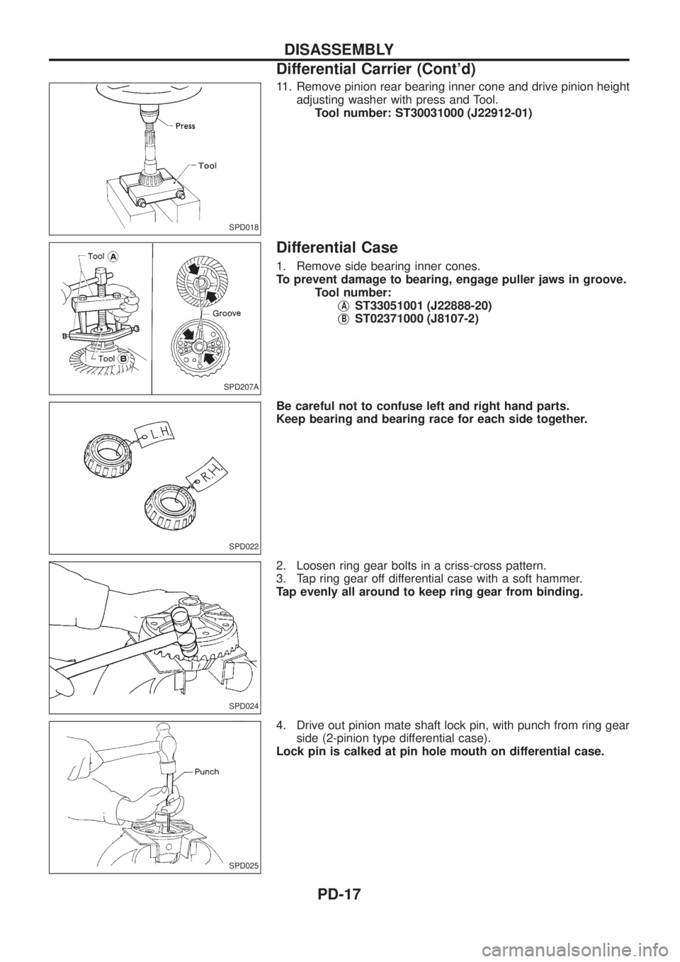
11. Remove pinion rear bearing inner cone and drive pinion heightadjusting washer with press and Tool.Toolnumber:ST30031000 (J22912-01)
Differential Case
1. Remove side bearing inner cones.
To prevent damage to bearing, engage puller jaws in groove. Tool number:j
AST33051001 (J22888-20)
j
BST02371000 (J8107-2)
Be careful not to confuse left and right hand parts.
Keep bearing and bearing race for each side together.
2. Loosen ring gear bolts in a criss-cross pattern.
3. Tap ring gear off differential case with a soft hammer.
Tap evenly all around to keep ring gear from binding.
4. Drive out pinion mate shaft lock pin, with punch from ring gear side (2-pinion type differential case).
Lock pin is calked at pin hole mouth on differential case.
SPD018
SPD207A
SPD022
SPD024
SPD025
DISASSEMBLY
Differential Carrier (Cont'd)
PD-17