2006 NISSAN PATROL fuse
[x] Cancel search: fusePage 798 of 1226
Voltage check method
To help in understanding the diagnosis of open circuits please refer to the previous schematic.
In any powered circuit, an open can be found by methodically checking the system for the presence of volt-
age. This is done by switching the DMM to the voltage function.
1. Connect one probe of the DMM to a known good ground.
2. Begin probing at one end of the circuit and work your way to the other end.
3. With SW1 open, probe at SW1 to check for voltage.
voltage; open is further down the circuit than SW1.
no voltage; open is between fuse block and SW1 (point A).
4. Close SW1 and probe at relay.
voltage; open is further down the circuit than the relay.
no voltage; open is between SW1 and relay (point B).
5. Close the relay and probe at the solenoid.
voltage; open is further down the circuit than the solenoid.
no voltage; open is between relay and solenoid (point C).
Any powered circuit can be diagnosed using the approach in the above example.
TESTING FOR ``SHORTS'' IN THE CIRCUIT
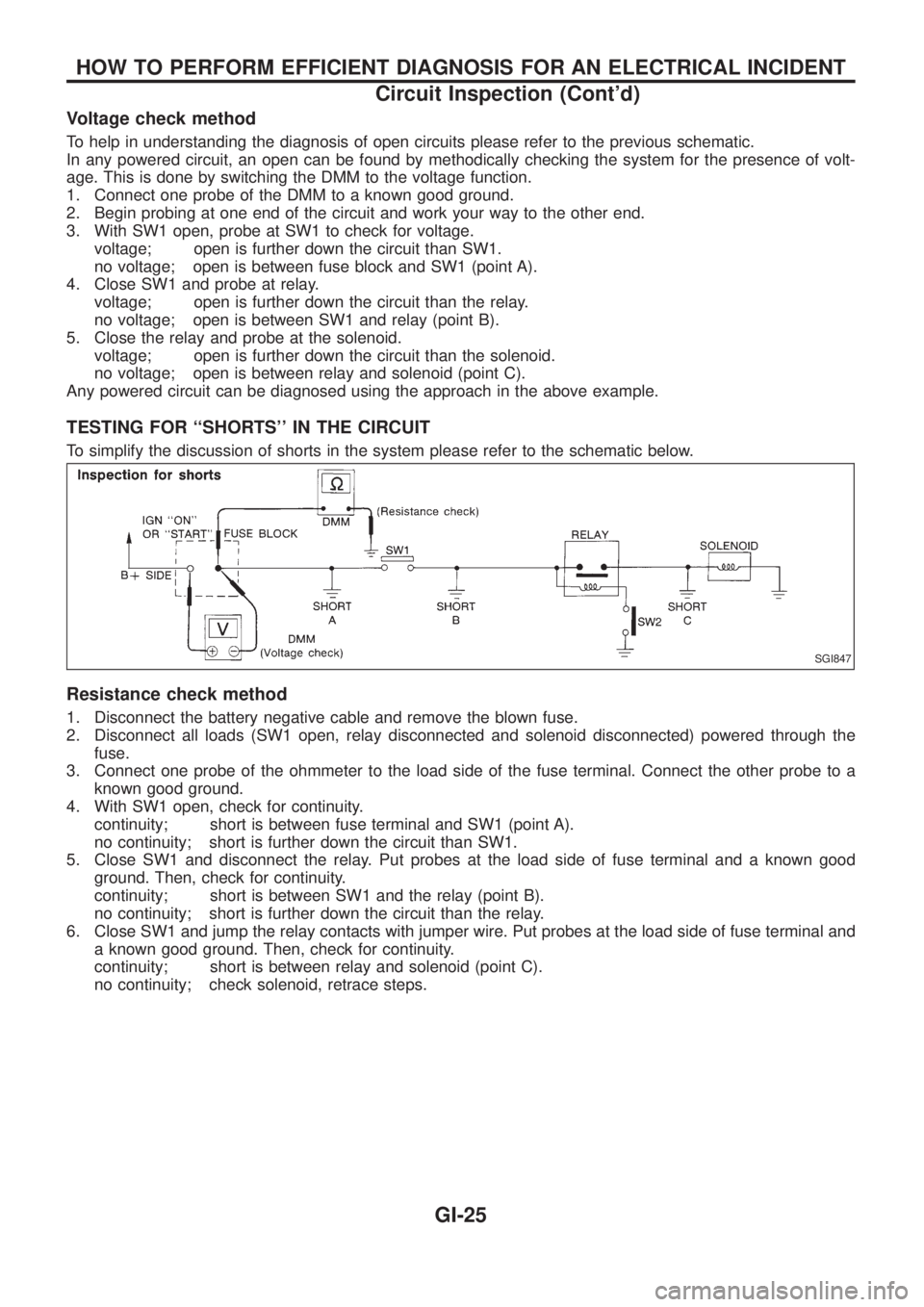
To simplify the discussion of shorts in the system please refer to the schematic below.
Resistance check method
1. Disconnect the battery negative cable and remove the blown fuse.
2. Disconnect all loads (SW1 open, relay disconnected and solenoid disconnected) powered through the
fuse.
3. Connect one probe of the ohmmeter to the load side of the fuse terminal. Connect the other probe to a
known good ground.
4. With SW1 open, check for continuity.
continuity; short is between fuse terminal and SW1 (point A).
no continuity; short is further down the circuit than SW1.
5. Close SW1 and disconnect the relay. Put probes at the load side of fuse terminal and a known good
ground. Then, check for continuity.
continuity; short is between SW1 and the relay (point B).
no continuity; short is further down the circuit than the relay.
6. Close SW1 and jump the relay contacts with jumper wire. Put probes at the load side of fuse terminal and
a known good ground. Then, check for continuity.
continuity; short is between relay and solenoid (point C).
no continuity; check solenoid, retrace steps.
SGI847
HOW TO PERFORM EFFICIENT DIAGNOSIS FOR AN ELECTRICAL INCIDENT
Circuit Inspection (Cont'd)
GI-25
Page 799 of 1226
Voltage check method
1. Remove the blown fuse and disconnect all loads (i.e. SW1 open, relay disconnected and solenoid discon-
nected) powered through the fuse.
2. Turn the ignition key to the ON or START position. Verify battery voltage at the B
+side of the fuse ter-
minal (one lead on the B
+terminal side of the fuse block and one lead on a known good ground).
3. With SW1 open and the DMM leads across both fuse terminals, check for voltage.
voltage; short is between fuse block and SW1 (point A).
no voltage; short is further down the circuit than SW1.
4. With SW1 closed, relay and solenoid disconnected and the DMM leads across both fuse terminals, check
for voltage.
voltage; short is between SW1 and the relay (point B).
no voltage; short is further down the circuit than the relay.
5. With SW1 closed, relay contacts jumped with fused jumper wire check for voltage.
voltage; short is down the circuit of the relay or between the relay and the disconnected solenoid
(point C).
no voltage; retrace steps and check power to fuse block.
GROUND INSPECTION
Ground connections are very important to the proper operation of electrical and electronic circuits. Ground
connections are often exposed to moisture, dirt and other corrosive elements. The corrosion (rust) can become
an unwanted resistance. This unwanted resistance can change the way a circuit works.
Electronically controlled circuits are very sensitive to proper grounding. A loose or corroded ground can dras-
tically affect an electronically controlled circuit. A poor or corroded ground can easily affect the circuit. Even
when the ground connection looks clean, there can be a thin ®lm of rust on the surface.
When inspecting a ground connection follow these rules:
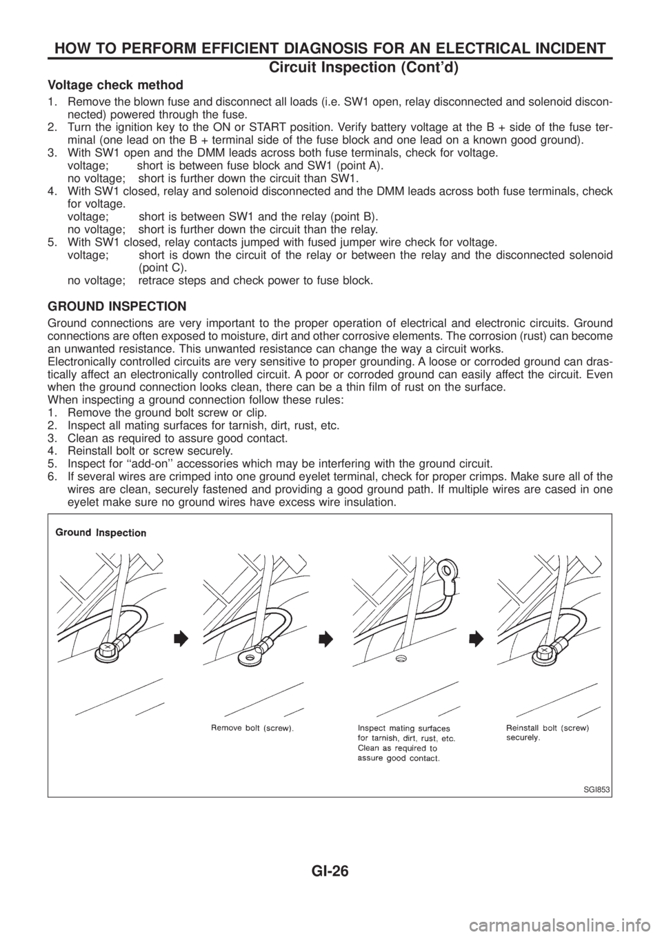
1. Remove the ground bolt screw or clip.
2. Inspect all mating surfaces for tarnish, dirt, rust, etc.
3. Clean as required to assure good contact.
4. Reinstall bolt or screw securely.
5. Inspect for ``add-on'' accessories which may be interfering with the ground circuit.
6. If several wires are crimped into one ground eyelet terminal, check for proper crimps. Make sure all of the
wires are clean, securely fastened and providing a good ground path. If multiple wires are cased in one
eyelet make sure no ground wires have excess wire insulation.
SGI853
HOW TO PERFORM EFFICIENT DIAGNOSIS FOR AN ELECTRICAL INCIDENT
Circuit Inspection (Cont'd)
GI-26
Page 805 of 1226
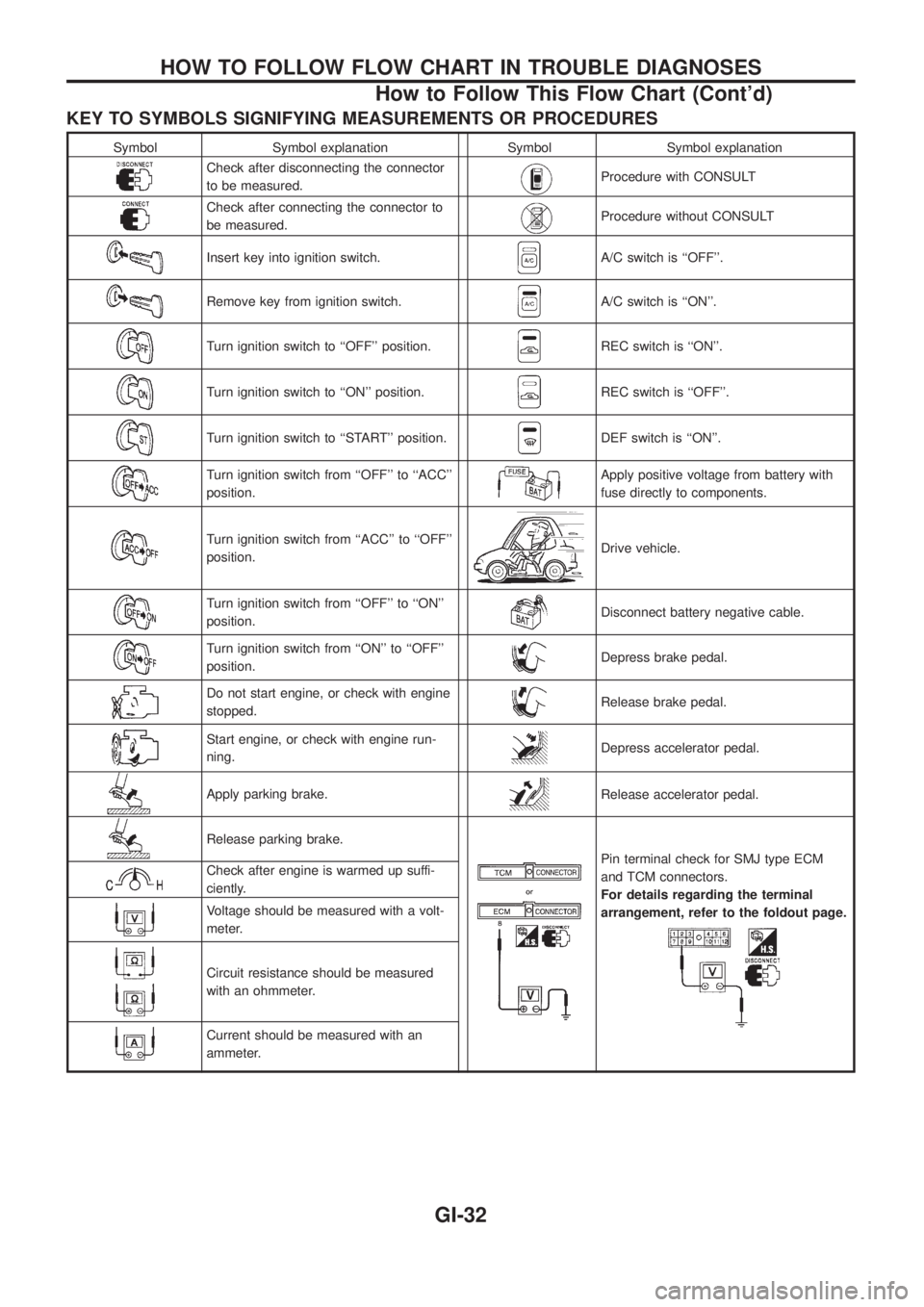
KEY TO SYMBOLS SIGNIFYING MEASUREMENTS OR PROCEDURES
Symbol Symbol explanation Symbol Symbol explanation
Check after disconnecting the connector
to be measured.Procedure with CONSULT
Check after connecting the connector to
be measured.Procedure without CONSULT
Insert key into ignition switch.A/C switch is ``OFF''.
Remove key from ignition switch.A/C switch is ``ON''.
Turn ignition switch to ``OFF'' position.REC switch is ``ON''.
Turn ignition switch to ``ON'' position.REC switch is ``OFF''.
Turn ignition switch to ``START'' position.DEF switch is ``ON''.
Turn ignition switch from ``OFF'' to ``ACC''
position.Apply positive voltage from battery with
fuse directly to components.
Turn ignition switch from ``ACC'' to ``OFF''
position.Drive vehicle.
Turn ignition switch from ``OFF'' to ``ON''
position.Disconnect battery negative cable.
Turn ignition switch from ``ON'' to ``OFF''
position.Depress brake pedal.
Do not start engine, or check with engine
stopped.Release brake pedal.
Start engine, or check with engine run-
ning.Depress accelerator pedal.
Apply parking brake.Release accelerator pedal.
Release parking brake.
Pin terminal check for SMJ type ECM
and TCM connectors.
For details regarding the terminal
arrangement, refer to the foldout page.Check after engine is warmed up suffi-
ciently.
Voltage should be measured with a volt-
meter.
Circuit resistance should be measured
with an ohmmeter.
Current should be measured with an
ammeter.
HOW TO FOLLOW FLOW CHART IN TROUBLE DIAGNOSES
How to Follow This Flow Chart (Cont'd)
GI-32
Page 823 of 1226
General Refrigerant Precautions
WARNING:
+Do not release refrigerant into the air. Use approved recovery/recycling equipment to capture the
refrigerant every time an air conditioning system is discharged.
+Always wear eye and hand protection (goggles and gloves) when working with any refrigerant or
air conditioning system.
+Do not store or heat refrigerant containers above 52ÉC.
+Do not heat a refrigerant container with an open ¯ame; if container warming is required, place the
bottom of the container in a warm pail of water.
+Do not intentionally drop, puncture, or incinerate refrigerant containers.
+Keep refrigerant away from open ¯ames: poisonous gas will be produced if refrigerant burns.
+Refrigerant will displace oxygen, therefore be certain to work in well ventilated areas to prevent
suffocation.
+Do not introduce compressed air to any refrigerant container or refrigerant component.
Precautions for Refrigerant Connection
A new type refrigerant connection has been introduced to all refrigerant lines except the following location.
+Expansion valve to cooling unit
+A part of high-pressure line
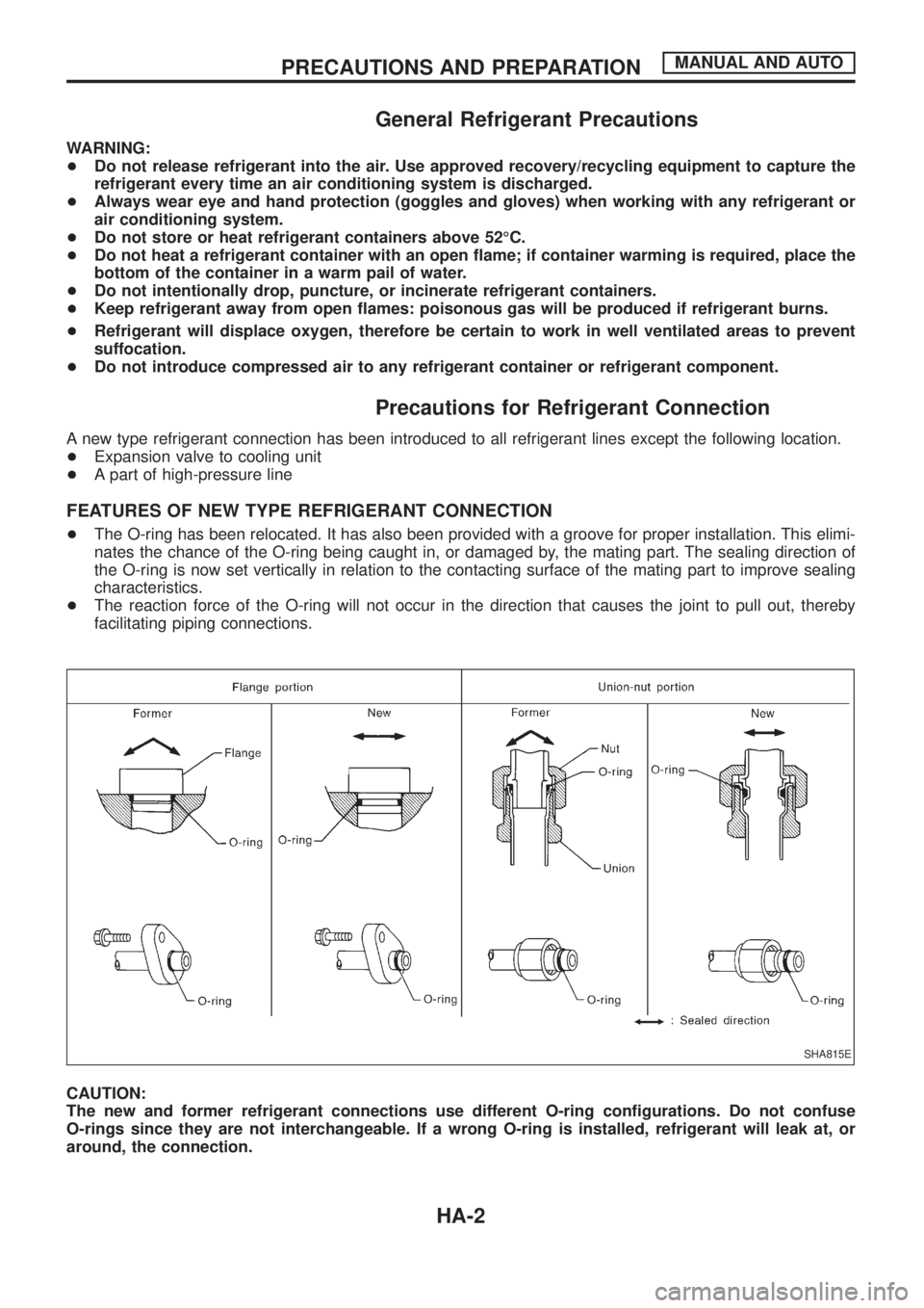
FEATURES OF NEW TYPE REFRIGERANT CONNECTION
+The O-ring has been relocated. It has also been provided with a groove for proper installation. This elimi-
nates the chance of the O-ring being caught in, or damaged by, the mating part. The sealing direction of
the O-ring is now set vertically in relation to the contacting surface of the mating part to improve sealing
characteristics.
+The reaction force of the O-ring will not occur in the direction that causes the joint to pull out, thereby
facilitating piping connections.
CAUTION:
The new and former refrigerant connections use different O-ring con®gurations. Do not confuse
O-rings since they are not interchangeable. If a wrong O-ring is installed, refrigerant will leak at, or
around, the connection.
SHA815E
PRECAUTIONS AND PREPARATIONMANUAL AND AUTO
HA-2
Page 847 of 1226
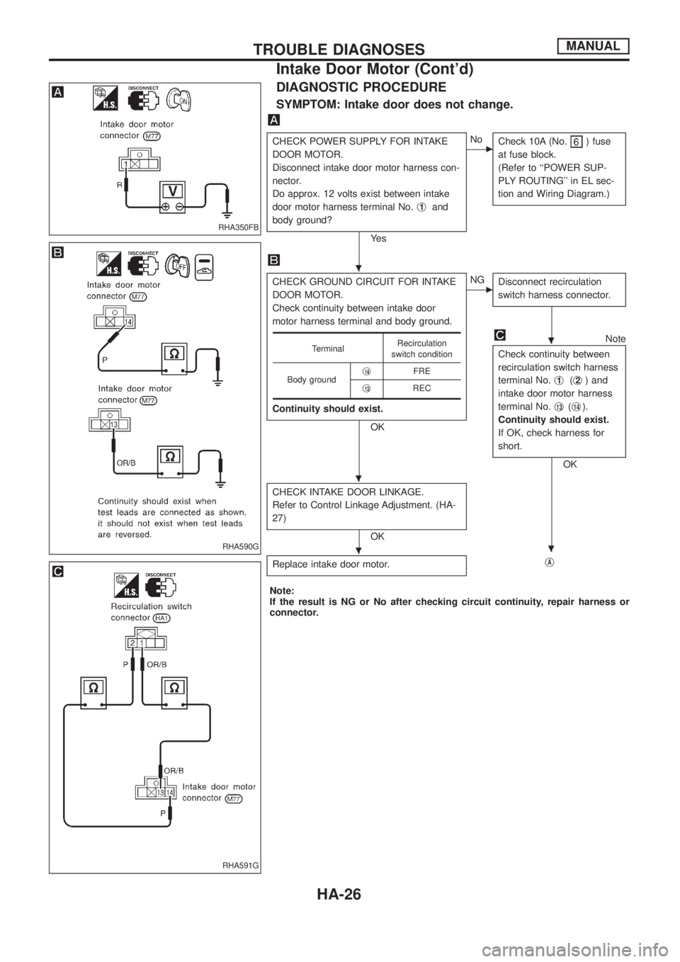
DIAGNOSTIC PROCEDURE
SYMPTOM: Intake door does not change.
CHECK POWER SUPPLY FOR INTAKE
DOOR MOTOR.
Disconnect intake door motor harness con-
nector.
Do approx. 12 volts exist between intake
door motor harness terminal No.j
1and
body ground?
Ye s
cNo
Check 10A (No.) fuse
at fuse block.
(Refer to ``POWER SUP-
PLY ROUTING'' in EL sec-
tion and Wiring Diagram.)
CHECK GROUND CIRCUIT FOR INTAKE
DOOR MOTOR.
Check continuity between intake door
motor harness terminal and body ground.
Continuity should exist.
OK
cNG
Disconnect recirculation
switch harness connector.
Note
Check continuity between
recirculation switch harness
terminal No.j
1(j2) and
intake door motor harness
terminal No.j
13(j14).
Continuity should exist.
If OK, check harness for
short.
OK
CHECK INTAKE DOOR LINKAGE.
Refer to Control Linkage Adjustment. (HA-
27)
OK
Replace intake door motor.
jA
TerminalRecirculation
switch condition
Body groundj
14FRE
j
13REC
Note:
If the result is NG or No after checking circuit continuity, repair harness or
connector.
RHA350FB
RHA590G
RHA591G
.
.
.
..
TROUBLE DIAGNOSESMANUAL
Intake Door Motor (Cont'd)
HA-26
Page 850 of 1226
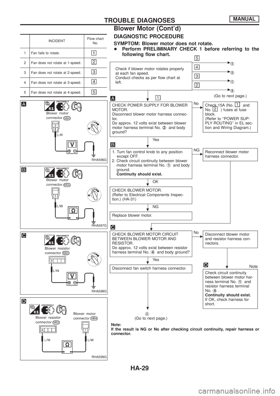
INCIDENTFlow chart
No.
1 Fan fails to rotate.
2 Fan does not rotate at 1-speed.
3 Fan does not rotate at 2-speed.
4 Fan does not rotate at 3-speed.
5 Fan does not rotate at 4-speed.
DIAGNOSTIC PROCEDURE
SYMPTOM: Blower motor does not rotate.
+Perform PRELIMINARY CHECK 1 before referring to the
following ¯ow chart.
Check if blower motor rotates properly
at each fan speed.
Conduct checks as per ¯ow chart at
left.
cjE
cjD
cjC
cjB
(Go to next page.)
CHECK POWER SUPPLY FOR BLOWER
MOTOR.
Disconnect blower motor harness connec-
tor.
Do approx. 12 volts exist between blower
motor harness terminal No.j
2and body
ground?
Ye s
cNo
Check 15A (No.and
No.) fuses at fuse
block.
(Refer to ``POWER SUP-
PLY ROUTING'' in EL sec-
tion and Wiring Diagram.)
1. Turn fan control knob to any position
except OFF.
2. Check circuit continuity between blower
motor harness terminal No.j
1and body
ground.
Continuity should exist.
OK
cNG
Reconnect blower motor
harness connector.
CHECK BLOWER MOTOR.
(Refer to Electrical Components Inspec-
tion.) (HA-31)
NG
Replace blower motor.
.
CHECK BLOWER MOTOR CIRCUIT
BETWEEN BLOWER MOTOR AND
RESISTOR.
Do approx. 12 volts exist between resistor
harness terminal No.j
4and body ground?
Ye s
cNo
Disconnect blower motor
and resistor harness con-
nectors.
Disconnect fan switch harness connector.Note
Check circuit continuity
between blower motor har-
ness terminal No.j
1and
resistor harness terminal
No.j
4.
Continuity should exist.
If OK, check harness for
short.
jA(Go to next page.)
Note:
If the result is NG or No after checking circuit continuity, repair harness or
connector.
RHA596G
RHA597G
RHA598G
RHA599G
.
.
.
.
..
.
TROUBLE DIAGNOSESMANUAL
Blower Motor (Cont'd)
HA-29
Page 865 of 1226
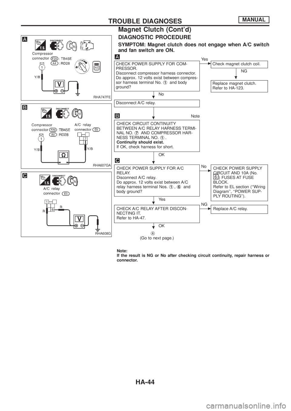
DIAGNOSTIC PROCEDURE
SYMPTOM: Magnet clutch does not engage when A/C switch
and fan switch are ON.
CHECK POWER SUPPLY FOR COM-
PRESSOR.
Disconnect compressor harness connector.
Do approx. 12 volts exist between compres-
sor harness terminal No.j
1and body
ground?
No
cYe s
Check magnet clutch coil.
NG
Replace magnet clutch.
Refer to HA-123.
Disconnect A/C relay.
Note
CHECK CIRCUIT CONTINUITY
BETWEEN A/C RELAY HARNESS TERMI-
NAL NO.j
7AND COMPRESSOR HAR-
NESS TERMINAL NO.j1.
Continuity should exist.
If OK, check harness for short.
OK
CHECK POWER SUPPLY FOR A/C
RELAY.
Disconnect A/C relay.
Do approx. 12 volts exist between A/C
relay harness terminal Nos.j
1,j6and
body ground?
Ye s
cNo
CHECK POWER SUPPLY
CIRCUIT AND 10A (No.
) FUSES AT FUSE
BLOCK.
Refer to EL section (``Wiring
Diagram'', ``POWER SUP-
PLY ROUTING'').
CHECK A/C RELAY AFTER DISCON-
NECTING IT.
Refer to HA-47.
OK
cNG
Replace A/C relay.
jA(Go to next page.)
Note:
If the result is NG or No after checking circuit continuity, repair harness or
connector.
RHA747FE
RHA607GA
RHA608G
.
.
.
.
.
.
TROUBLE DIAGNOSESMANUAL
Magnet Clutch (Cont'd)
HA-44
Page 867 of 1226
jB
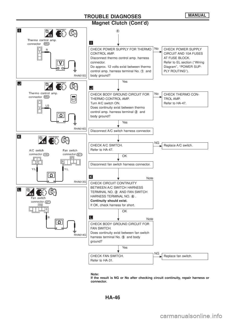
CHECK POWER SUPPLY FOR THERMO
CONTROL AMP.
Disconnect thermo control amp. harness
connector.
Do approx. 12 volts exist between thermo
control amp. harness terminal No.j
1and
body ground?
Ye s
cNo
CHECK POWER SUPPLY
CIRCUIT AND 10A FUSES
AT FUSE BLOCK.
Refer to EL section (``Wiring
Diagram'', ``POWER SUP-
PLY ROUTING'').
CHECK BODY GROUND CIRCUIT FOR
THERMO CONTROL AMP.
Turn A/C switch ON.
Does continuity exist between thermo
control amp. harness terminalj
2and
body ground?
Ye s
cNo
CHECK THERMO CON-
TROL AMP.
Refer to HA-47.
Disconnect A/C switch harness connector.
CHECK A/C SWITCH.
Refer to HA-47.
OK
cNG
Replace A/C switch.
Disconnect fan switch harness connector.
Note
CHECK CIRCUIT CONTINUITY
BETWEEN A/C SWITCH HARNESS
TERMINAL NO.j
2AND FAN SWITCH
HARNESS TERMINAL NO.j
6.
Continuity should exist.
If OK, check harness for short.
OK
Note
CHECK BODY GROUND CIRCUIT FOR
FAN SWITCH.
Does continuity exist between fan switch
harness terminal No.j
5and body
ground?
Ye s
CHECK FAN SWITCH.
Refer to HA-31.
cNG
Replace fan switch.
Note:
If the result is NG or No after checking circuit continuity, repair harness or
connector.
RHA615G
RHA616G
RHA613G
RHA614G
.
.
.
.
.
.
.
.
TROUBLE DIAGNOSESMANUAL
Magnet Clutch (Cont'd)
HA-46