Page 338 of 364
GENERAL INFORMATION
FUEL SUPPLY13C-2
GENERAL INFORMATION
M2134000100639
The fuel system consists of the following compo-
nents:
•Fuel injector
•Fuel delivery pipe
•Fuel pressure regulator <4G1>
•Fuel vapour canister
•Fuel tank
•Fuel tank pump and gauge assembly
SPECIFICATIONS
ItemSpecification
Fuel tank capacity L45
Fuel pump typeElectric
Fuel pump pressure regulator control pressure kPa <4A9>324
Fuel pressure regulator control pressure kPa <4G1>294
Fuel injectorTy p eElector-magnetic
Quantity4
Evaporative emission control systemFuel vapour canister
Page 339 of 364

GENERAL INFORMATION
FUEL SUPPLY13C-3
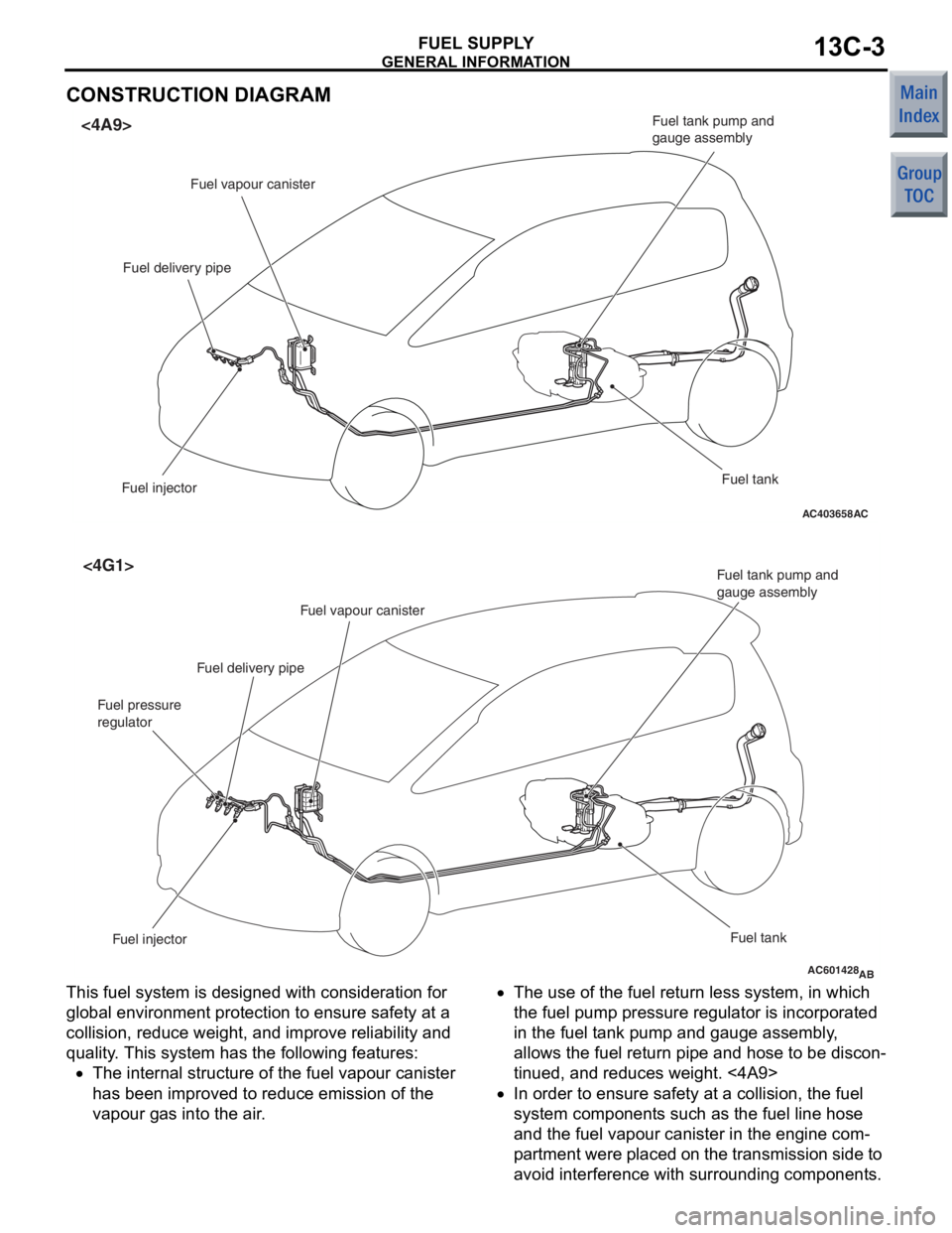
CONSTRUCTION DIAGRAM
AC403658AC
<4A9>
Fuel vapour canister
Fuel delivery pipe
Fuel injector Fuel tank
Fuel tank pump and
gauge assembly
AC601428AB
<4G1>
Fuel injector
Fuel tank
Fuel tank pump and
gauge assembly
Fuel vapour canister
Fuel delivery pipe
Fuel pressure
regulator
This fuel system is designed with considerat ion fo r
globa
l environ ment protection to ensure safety at a
collision,
reduce weigh t, and imp r ove re lia bility a nd
quality
. This system h a s th e following feature s :
•The intern al struct ure of t he fue l va pour canister
has bee
n improve d to re duce emission o f the
va
pour g a s into the air .
•The use of the fuel re turn less system, in wh ich
the
fuel pump pressure re gula t or is incorpora t ed
in
the fu el t ank pump and gauge assemb ly ,
allows t
he fue l return pipe and h o se to be d i scon
-
tinued, and red u ces weigh t. <4A9>
•In or der to ensu r e saf e ty a t a collision, the fuel
syst
em comp onent s such as the fue l line ho se
and
the fu el vapour canister in the engine com
-
pa rt men t were placed o n t he t r ansmissio n sid e to
avoid
interfe r ence with surroun ding componen t s .
Page 340 of 364

FUEL TANK
FUEL SUPPLY13C-4
•A resin coating is treated on the underfloor fuel
line pipes, improving reliability.
•A fuel tank pump with low power consumption
has been adopted to reduce the alternator load.
•A plastic tank pump and gauge assembly is used
to reduce weight.
•The fuel line tube and fuel line hose are made of
the material, which does not allow fuel vapour to
pass through it as much as possible, so that the
vapour gas emission to the air is reduced.
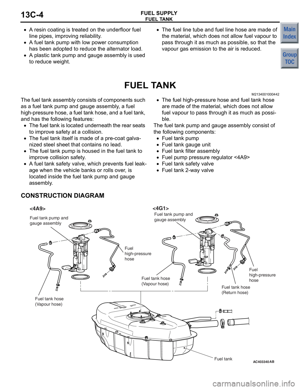
FUEL TANK
M2134001000442
The fuel tank assembly consists of components such
as a fuel tank pump and gauge assembly, a fuel
high-pressure hose, a fuel tank hose, and a fuel tank,
and has the following features:
•The fuel tank is located underneath the rear seats
to improve safety at a collision.
•The fuel tank itself is made of a pre-coat galva-
nized steel sheet that contains no lead.
•The fuel tank pump is housed in the fuel tank to
improve collision safety.
•A fuel tank safety valve, which prevents fuel leak-
age when the vehicle banks or rolls over, is
located inside the fuel tank pump and gauge
assembly.
•The fuel high-pressure hose and fuel tank hose
are made of the material, which does not allow
fuel vapour to pass through it as much as possi
-
ble.
The fuel tank pump and gauge assembly consist of
the following components:
•Fuel tank pump
•Fuel tank gauge unit
•Fuel tank filter assembly
•Fuel pump pressure regulator <4A9>
•Fuel tank safety valve
•Fuel tank 2-way valve
CONSTRUCTION DIAGRAM
AC403340AB
<4A9><4G1>
Fuel tank
Fuel tank pump and
gauge assembly
Fuel tank pump and
gauge assembly
Fuel
high-pressure
hose Fuel
high-pressure
hose
Fuel tank hose
(Vapour hose) Fuel tank hose
(Vapour hose)
Fuel tank hose
(Return hose)
Page 363 of 364

EMISSION CONTROL
ENGINE AND EMISSION CONTROL17-3
EMISSION CONTROL
GENERAL INFORMATION <4A9>M2171000100838
Although the emission control systems are basically
the same as those of the 4G1-Non-Turbo engine
used in the COLT, the following improvements have
been added.•The adoption of the catalytic converter just
beneath exhaust manifold realizes the earlier
activation.
•The adoption of the dual oxygen sensor has
increased reliability air/fuel ratio control.
•
SystemRemarks
Crank case ventilaton systemClosed type
Evaporative emission control systemElectronic control type with duty signal
Exhaust gas recirculation (EGR) system Electronic control (stepper motor) type
Air/fuel ratio closed loop controlOxygen sensor signal used
Catalytic converterThree-way catalytic converter
The abolition of the EGR system .
EMISSION CONTROL SYSTEM DIAGRAM
AK402829
Oxygen sensor (front)
Oxygen sensor (rear)
Air
inlet
EGR valve
(stepper motor)
Canister
Purge control
solenoid valve
Injector
PCV valve
ACCatalytic converter From
fuel pump
Page 364 of 364

EMISSION CONTROL
ENGINE AND EMISSION CONTROL17-4
GENERAL INFORMATION <4G1>
M2171000100849
Although the emission control systems are basically
the same as those of the 4G1-Non-Turbo engine
used in the COLT, the following improvements have
been added.
•The adoption of the catalytic converter just
beneath turbo charger and under the floor
increased the performance of the emission con
-
trols.
•The adoption of the check valve between the
purge control solenoid valve and the canister pro
-
tects the regurgitation as turbocharging.
•
SystemRemarks
Crank case ventilaton systemClosed type
Evaporative emission control systemElectronic control type with duty signal
Air/fuel ratio closed loop controlOxygen sensor signal used
Catalytic converterThree-way catalytic converter
The abolition of the EGR system
EMISSION CONTROL SYSTEM DIAGRAM
AK600530AB
Canister
Purge control
solenoid valve Fuel pressure control
solenoid valve
Check valve
Waste gate
solenoid valve Waste gate
actuator
Air
inlet
Catalytic
converter
Catalytic
converter Injector
From
fuel pump
Fuel pressure
regulator
To
fuel tank
Oxygen sensor
(front)
Oxygen sensor
(rear)