Page 212 of 364

TECHNICAL FEATURES
GENERAL00-27
POWER WINDOW WITH SAFETY MECHA-
NISM
The power window with safety mechanism has been
adopted to automatically roll down and stop the door
window glass as soon as the occurrence of jamming
is detected at the time of rolling up the door window
glass.
SUNROOF WITH SA FETY MECHANISM
The sunroof with safe ty mechanism has been
adopted so that the roof lid glass can move in the
reverse direction and stop when application of exter
-
nal force hinders the movement during the sliding to
close or tilt down operation.
TRIMS AND HEADLINING
The head impact absorption structure has been
adopted for the pillar trim, quarter trim, and headlin
-
ing so that impact towards the head of a passenger
can be reduced.
OTHER SAFETY FEATURES
•3-point ELR seat belts
•Child-protection rear door locks
•Front fog lamps
EQUIPMENTSM2000026000221
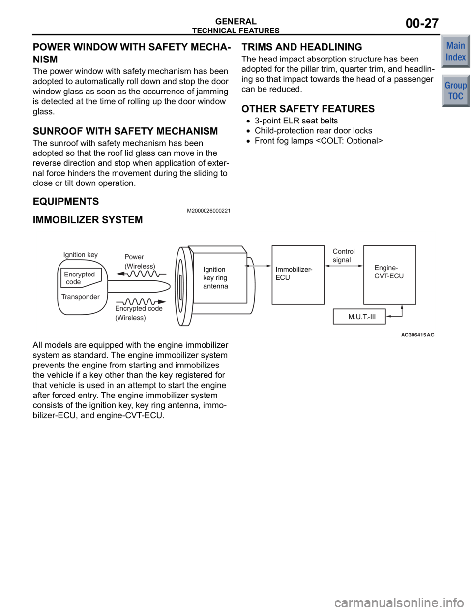
IMMOBILIZER SYSTEM
AC306415AC
M.U.T.-III
Ignition
key ring
antenna
Immobilizer-
ECU
Ignition key
Encrypted
code
Transponder Power
(Wireless)
Encrypted code
(Wireless) Control
signal
Engine-
CVT-ECU
All models are equipped with the e ngine immobilizer
system as st andard. The en gine immobilizer syst em
preve nts the engin e from starting and immobilizes
the vehicle if a key o ther tha n the key registered for
that vehicle is used in an attempt to start the e ngine
af te r forced entry . The en gine immobilizer syst em
consist s of the ignition key, key ring antenna, immo
-
bilizer-ECU, and engine-CVT-ECU.
Page 240 of 364

ELECTRICAL POWER STEERING
POWER STEERING37-7
ELECTRICAL POWER STEERING
GENERAL INFORMATIONM2370000100862
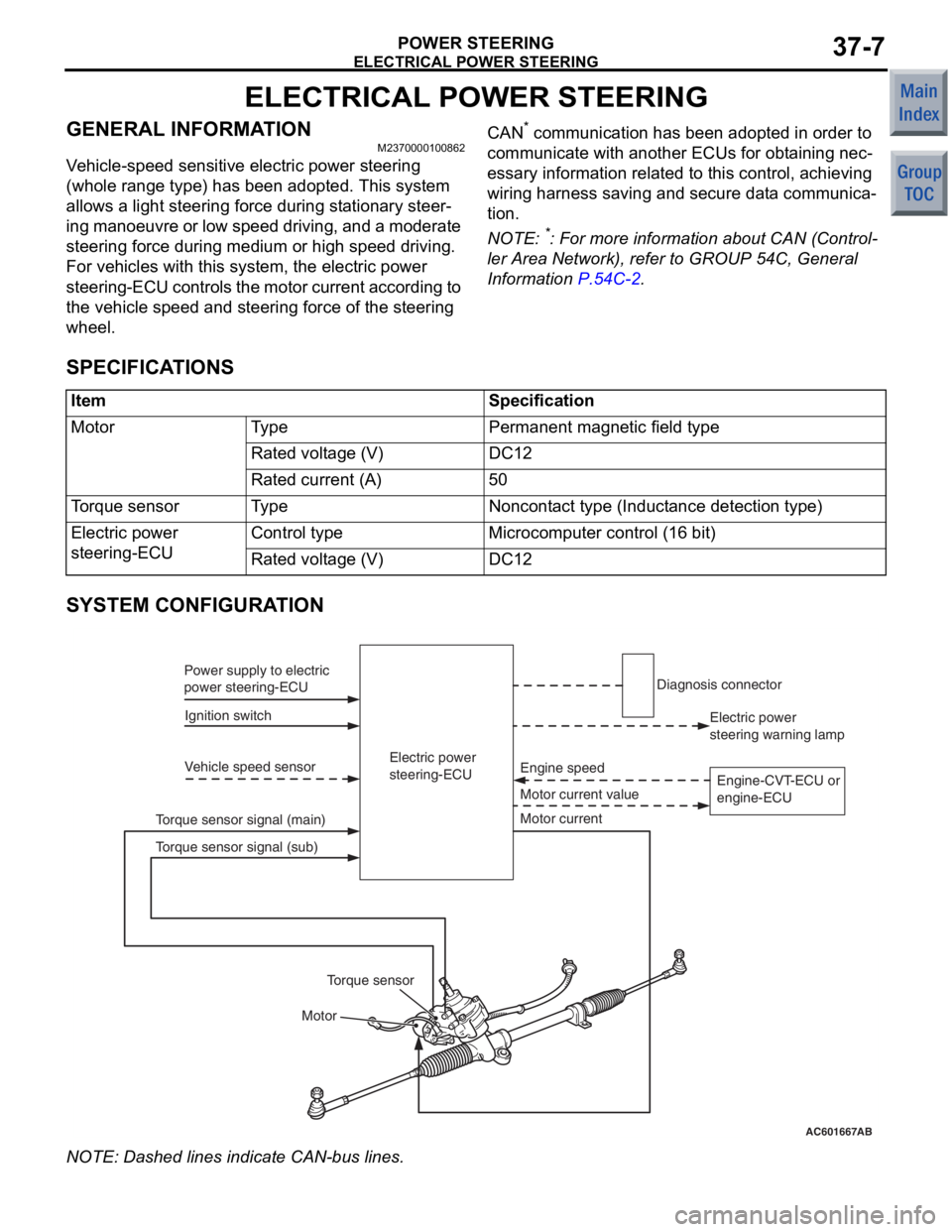
Vehicle-speed sensitive electric power steering
(whole range type) has been adopted. This system
allows a light steering force during stationary steer
-
ing manoeuvre or low speed driving, and a moderate
steering force during medium or high speed driving.
For vehicles with this system, the electric power
steering-ECU controls the motor current according to
the vehicle speed and steering force of the steering
wheel.
CAN* communication has been adopted in order to
communicate with another ECUs for obtaining nec
-
essary information related to this control, achieving
wiring harness saving and secure data communica
-
tion.
NOTE: *: For more information about CAN (Control-
ler Area Network), refer to GROUP 54C, General
Information
P.54C-2.
SPECIFICATIONS
ItemSpecification
MotorTy p ePermanent magnetic field type
Rated voltage (V)DC12
Rated current (A)50
Torque sensorTy p eNoncontact type (Inductance detection type)
Electric power
steering-ECUControl typeMicrocomputer control (16 bit)
Rated voltage (V)DC12
SYSTEM CONFIGURATION
AC601667AB
Electric power
steering-ECU
Ignition switch
Power supply to electric
power steering-ECU
Vehicle speed sensor
Motor Motor current value Engine speed
Torque sensor signal (main) Electric power
steering warning lamp
Diagnosis connector
Motor current
Torque sensor
Torque sensor signal (sub) Engine-CVT-ECU or
engine-ECU
NO
TE: Dash ed lines indicat e CAN-bu s lines.
Page 244 of 364

ELECTRICAL POWER STEERING
POWER STEERING37-11
OPERATION
M2370000700110
IGNITION SWITCH ON
Ignition supply voltage is applied to the electric
power steering-ECU, and the ECU enters standby
mode.
IGNITION SWITCH ON
AC601668AC207635 AB
Electric power
steering-ECU
OFF
OFF MotorMotor current signal
Maximum limit value (50A)
Engine speed
Engine speed
ON
500 r/min or 15 km/h
max 0.5s 0.7s
Motor output Determination of motor
control start Temporary increase of motor
assist limit value
Engine-CVT-ECU or
engine-ECU
1.
Whe n th e e ngine is st arted, the en gine sp eed sig-
nal sent from the en gine -CVT -ECU or
eng
ine-ECU is inp u t to th e ele c tric power steer
-
ing-ECU.
2. Af ter st a r ting the engine, the electric power ste e r-
ing-ECU judges the engin e st atu s "ENGINE
SPEED ON"
when the engine speed reaches 500
r/min or
the vehicle speed reaches 1 5 km/h or
more, the
n the p o wer assist functio n is ready .
STEERING WHEEL OPERAT ION
AC400096
AC206443AB
Electric power
steering-ECU
Torque
sensor
Torque sensor
Motor Motor
Motor current
Torque sensor signal (main)
Torque sensor signal (sub)
F A IL- S AFE FUNCTION OPERA T ION
Duri ng t h e f a il -s af e m o d e , t h e el ect r ic powe r st ee rin g
operate
s as a manual ste e ring system.
Page 270 of 364

MULTI-DISTRIBUTION INPUT/OUTPUT BY CIRCUIT
SMART WIRING SYSTEM (SWS)54B-4
MULTI-DISTRIBUTION INPUT/OUTPUT BY CIRCUIT
M2541002000649
Multi-distribution is employed by the following cir-
cuits. The relation of the input switches, sensors,
ECUs connected by multi-distribution lines, and out
-
puts are also shown below.
Buzzer
•Lamp reminder buzzer function
•Door-ajar warning buzzer function
•
AC601725AB
• Ignition switch (IG1)
• Driver's door switch
• Hazard lamp switch
Combination meter
• Vehicle speed signal �
• Ignition switch (IG1) ETACS-ECU
Circuit and Input Switch
ECUs and Switches
Connected by
Multi-DistributionOutput
Buzzer (built-in ETACS-ECU)
: CAN communication line : SWS communication line
Column switch
(Lighting or turn
signal lamp
switch)
T u rn-sign a l op eratio n so und fun c tion
Keyless e n try
•Multi-mode keyless en try system
•Keyless entry hazard a n swerba ck function
•
AC401127AB
• Respective door switches
• Key reminder switch
• Keyless entry transmitter ETACS-ECU
•
Electric retractable remote
controlled mirror
• Respective turn signal lamps
• Room lamp
Circuit and Input Switch
ECUs and Switches
Connected by
Multi-DistributionOutput
Keyless ent
ry roo m la mp a n swerba ck funct i on
Page 271 of 364
MULTI-DISTRIBUTION INPUT/OUTPUT BY CIRCUIT
SMART WIRING SYSTEM (SWS)54B-5
Power window
•
AC401129AB
ETACS-ECU
Circuit and Input SwitchECUs and Switches
Connected by
Multi-DistributionOutput
Power window relay
: CAN communication line
• Ignition switch (IG1)
• Driver's door switch
• Passenger's door switch
Combination meter
• Ignition switch (IG1)
Power win dow timer functio n
Wi n dshield wipe r a nd wa sher
•Windshi eld mist wipe r
•Vehicle spe ed-dep enden t variable windshield
in
termittent wiper
•Windsh i eld low speed wiper
•Windshi eld high spe ed wipe r
•
AC401803
ETACS-ECU
AB
• Ignition switch (IG1)
• Ignition switch (ACC)
Combination meter
• Ignition switch (IG1)
• Vehicle speed signal
Circuit and Input SwitchECUs and Switches
Connected by
Multi-DistributionOutput
Column switch
(Windshield
wiper and washer
switch)
• Windshield wiper motor
• Windshield washer motor
: SWS communication line
: CAN communication line
W i n d s hi e l d wa s h er
Page 272 of 364
MULTI-DISTRIBUTION INPUT/OUTPUT BY CIRCUIT
SMART WIRING SYSTEM (SWS)54B-6
Rear wiper washer
•Rear wiper•
AC207065
ETACS-ECU
AB
Circuit and Input Switch
ECUs and Switches
Connected by
Multi-Distribution
Output
• Ignition switch (IG1)
• Ignition switch (ACC)
Engine-CVT-ECU
• Inhibitor switch
Combination meter
•
Ignition switch (IG1) Column switch
(Rear wiper and
washer switch)
• Rear wiper motor
• Rear washer motor
: SWS communication line
: CAN communication line
Rear washer
Lighting
•Headlamp , t a il lamp•
AC401132AC
• Ignition switch (IG1)
• Fog lamp switch
• Driver's door switch
Combination meter
• High beam indicator lamp
• Fog lamp indicator lamp
•
Illumination lamps
• Headlamp
• Tail lamps
• Fog lamps
Combination meter
• Ignition switch (IG1) ETACS-ECU
Circuit and Input SwitchECUs and Switches
Connected by
Multi-Distribution
Output
Column switch
(Lighting switch)
: SWS communication line
: CAN communication line
Fog lamp
Page 273 of 364
MULTI-DISTRIBUTION INPUT/OUTPUT BY CIRCUIT
SMART WIRING SYSTEM (SWS)54B-7
Flasher timer
•Turn signal lamp•
AC207067
Combination meter
• Turn signal indicator lamps
ETACS-ECU
AB
Circuit and Input Switch
ECUs and Switches
Connected by
Multi-Distribution
Output
Column switch
(Turn-signal lamp
switch)
• Ignition switch (IG1)
• Hazard lamp switch
Combination meter
• Ignition switch (IG1) Turn signal lamp
: SWS communication line
: CAN communication line
Hazard warning lamp
Page 274 of 364

DIAGNOSTIC FUNCTION
SMART WIRING SYSTEM (SWS)54B-8
DIAGNOSTIC FUNCTION
M2541003000642
DIAGNOSIS CODE SET
For more information about diagnosis code output,
refer to the Workshop Manual.
SWS INPUT SIGNAL CHECK USING
M.U.T.-III
When the M.U.T.-III is connected to the diagnosis
connector and any of the SWS-linked switches is
operated, the PC buzzer sounds to evaluate whether
the switch is normal or not.
SWS INPUT SIGNAL CHECK AND ECU
CHECK BY USING SWS MONITOR
The switch signals sent by ECUs and the operations
of these ECUs can be confirmed by using the SWS
monitor and the M.U.T.-III.
INPUT SIGNALS THAT CAN BE CHECKED
Input signalCondition for sounding buzzerDisplay on
M.U.T.-III (when
SWS monitor is
used)
Ignition switch (ACC)Turn from "LOCK" (OFF) to "ACC" positionfrom OFF to ON
Ignition switch (IG1)Turn from "ACC" to "ON" positionfrom OFF to ON
Key reminder switchRemove the ignition key from ignition key cylinder
(form inserted position)from OFF to ON
Hazard lamp switchTurn from OFF to ONfrom OFF to ON
Fog lamp switch
Remote controlled mirror
switch (unfolding/folding
switch)
Speed signal When the speed changes from less than 10 km/h to
more than 10 km/hDisplays the
vehicle speed
Cranking signalWhile the ignition switch is in START position (while
cranking the engine)−
Selector lever P position signal
(parking)When the selector lever is shifted to the "P" position
(Ignition switch: ON or START)−
Selector lever R position signal
(reverse)When the selector lever is shifted to the "R" position
(Ignition switch: ON or START)−
Buzzer triggered by
ETACS-ECU
*1
When the following conditions are satisfied
•Ignition switch: LOCK (OFF) position
•Lighting switch: ON
•Driver’s door switch: ON (Driver’s door: OPEN)
ON
When requirements for sounding each warning buzzer
are not satisfiedOFF
Door switchDriver’s doorWhen door(s) or tailgate is opened from the closed
positionfrom OFF to ON
Passenger’s
door
Rear door
All door switchA door is opened when all the doors are closedfrom OFF to ON