Page 211 of 364

TECHNICAL FEATURES
GENERAL00-26
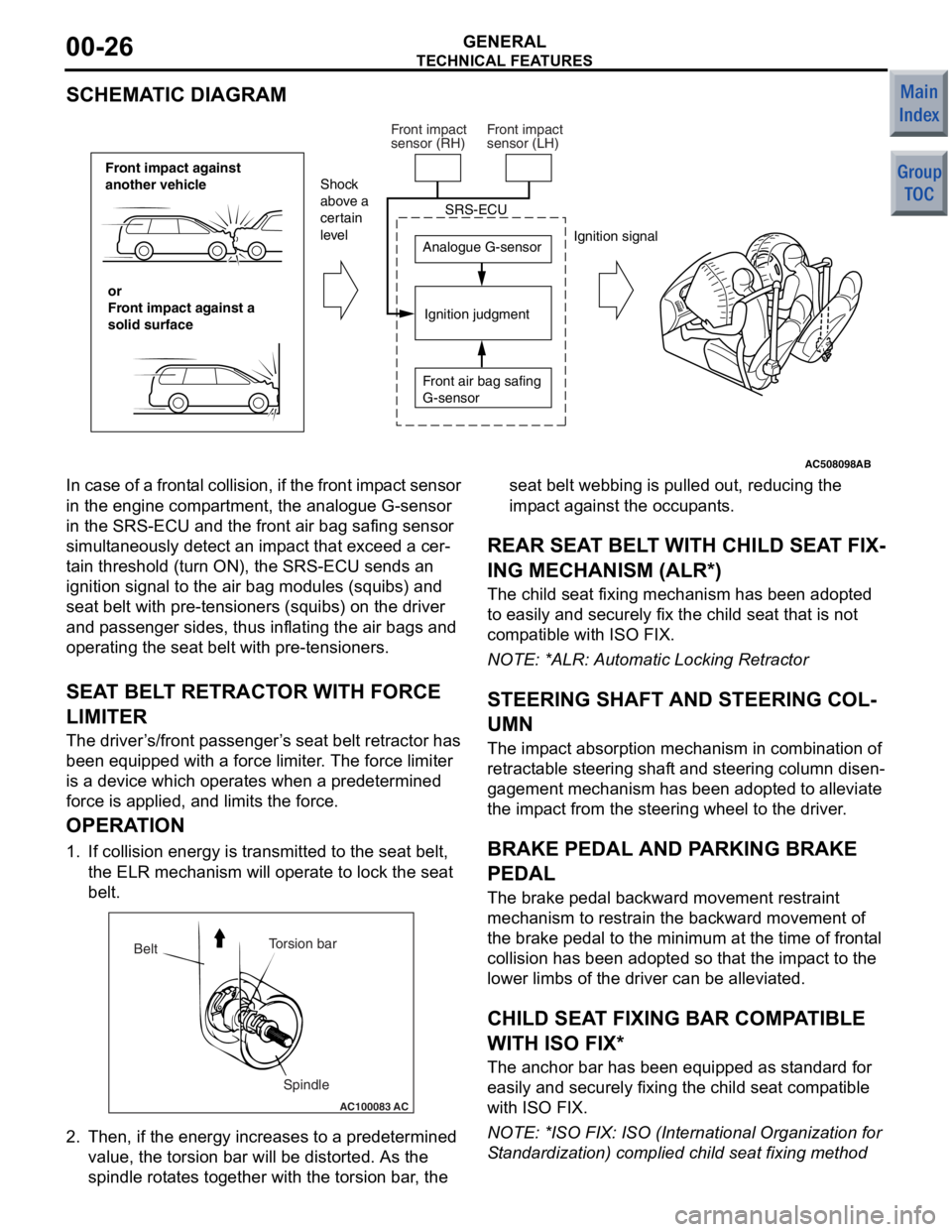
SCHEMATIC DIAGRAM
AC508098
Front impact against
another vehicleor
Front impact against a
solid surface Analogue G-sensor
Ignition judgment
Shock
above a
certain
level
Ignition signal
SRS-ECU
Front air bag safing
G-sensor
Front impact
sensor (RH)
Front impact
sensor (LH)
AB
In case of a
frontal collision, if the front imp act sensor
in the engine comp artment, the analogue G-sensor
in the SRS-ECU and t he front air bag safing sensor
simult aneously de tect an imp act th at excee d a cer
-
ta in threshold (turn ON), the SRS-ECU sen ds an
ignition signal to the air bag modules (squ ibs) and
seat belt with pre-te nsioners (squibs) on the driver
and p asseng er sides, thus inflating the air bag s and
operating the seat belt with pre -tensioner s.
SEAT BEL T RETRACT OR WITH FORCE
LIMITE R
The driver ’s /front p asseng er’s seat belt retractor has
been e quipped with a force limit er. The force limiter
is a device which operat es when a predetermined
force is applied, an d limits the for ce.
OPERA TION
1. If collision energy is transmit ted to the seat belt,
th e ELR mechanism will oper ate to lock the seat
be lt.
AC100083
Torsion bar
Spindle
Belt
AC
2.
Then, if the en ergy increase s to a prede termined
value , the to rsion bar will b e distorted . As th e
spind le rot ate s tog ether with the t orsion bar , the seat b
elt webb ing is p ulle d out, reducing th e
imp act against t he occupants.
REAR SEA T BELT WITH CHILD SEA T FIX-
ING MECHANISM (ALR*)
The child seat fixing mechanism h as b een ad opted
to easily and securely fix the child seat that is not
comp atible with ISO FIX.
NO TE: *ALR: Automatic Lockin g Retractor
STEERING SHAFT AND STEERING COL-
UMN
The impact ab sorption mech anism in combin ation of
retract able steerin g shaft and steering co lumn disen
-
gagement mecha nism has been ad opted t o alle viate
the imp act from th e steering wheel to the d rive r.
BRAKE PEDAL AND PA RKING BRAKE
PEDAL
The bra ke pe dal b ackward mo vement restraint
mechanism to restrain the backward movement of
the brake p edal to the minimum at the time o f f ront al
collision h as b een ad opted so that the impact to th e
lower limb s of the driver can be alleviated.
CHILD SEAT FIXING BAR COMP ATIBLE
WITH ISO FIX*
The an chor bar has been equipped a s st andard fo r
easily and secu rely fixing the child seat comp atible
with ISO FIX.
NO TE: *ISO F IX: ISO (In ternational Orga nization for
S tand ardizatio n) complied child se at fixing method
Page 221 of 364

GENERAL INFORMATION
FRONT AXLE26-2
GENERAL INFORMATION
M2260000100701
The front axle consists of front hub, wheel bearing,
knuckles and driveshafts, and has the following fea
-
tures:
•The wheel bearing incorporates magnetic
encoder for wheel speed sensing.
•The driveshaft incorporates EBJ-TJ type constant
velocity joint <4A9-CVT, 4A9-M/T (LS)>,
EBJ-ETJ type constant velocity joint <4A9-M/T
(VR)>, BJ-TJ type constant velocity joint <4G1>.
•The dynamic damper is mounted to reduce differ-
ential gear noise.
•The bracket assembly is mounted to reduce
torque steer. < 4G1>
•For environmental protection, a lead-free grease
is used on the joints.
EBJ(Eight Ball Fixed Joint):The use of the
smaller-sized eight balls inside the joint achieves
weight saving and compact size compared with a
BJ(Birfield Joint).
ETJ(Eco type Tripod Joint):This joint achieves
weight saving and compact size compared with a
TJ(Tripod Joint).
BJ:Birfield Joint
TJ:Tripod Joint
SPECIFICATIONS
Item4A94G1
CVTM/T
LSVR
Wheel bearingTy p eDouble-row angular contact ball bearing
Bearing (OD x ID) mm76 × 4076 × 4076 × 4076 × 40
DriveshaftJoint typeOuterEBJEBJEBJBJ
InnerTJTJETJTJ
Length (joint to joint)
× diameter mm
LH377 × 21.2377 × 21.2379 × 23352 × 24.9
RH688 × 21.2688 × 21.2664.3 × 23378.2 × 24.9
Page 222 of 364
GENERAL INFORMATION
FRONT AXLE26-3
CONSTRUCTION DIAGRAM
AC402000AG
<4A9>EBJ TJ (RH)
ETJ (RH)
Driveshaft (LH) TJ (LH)
ETJ (LH)
Dynamic damper
Driveshaft (RH)
Front hub KnuckleStrut assembly
Wheel bearing Dynamic damper
AC403318
AC511705AC
<4G1>
Front hub Knuckle
Strut assembly
BJDriveshaft (LH)
TJ
Wheel bearing Driveshaft (RH)
Bracket assembly
TJ
Dynamic damper
Page 239 of 364
CONSTRUCTION DESCRIPTION
POWER STEERING37-6
IMPACT-ABSORBING MECHANISM
Primary collision
AC207724AB
Lower shaft ALower shaft B
After impact
Before impact
When a
vehicle is crashed a nd the lower shaf t is
loade
d from the g earbox side, the lower shaf t A is
forced
into the lower sha f t B t o absorb an imp a ct
load.
Thus, the steering column will not be projecte d
into t
he p a ssenge r comp artme n t to red u ce possible
chest in
jurie s .
SECONDARY COLLISION
AC207397AB
Upper shaft B
Before impact
After impact Upper shaft A
When th
e driver ’ s we ight is loaded to the stee ring
wh
eel a f ter air ba g deployment, the steerin g co lumn
sep
a ration mechanism built into the rot a tiona l a x is of
the upp
er-side tilt lever (t ilt b o lt) a nd the lower-side
tilt
fulcrum (t ilt p i n) move s the stee ring colu mn
assembly fo
rwa r d. The upper shaf t can also b e fur
-
ther retrac ted forward as sh own in the figure.