2006 MITSUBISHI COLT drive shaft
[x] Cancel search: drive shaftPage 57 of 364

BASE ENGINE
ENGINE MECHANICAL <4A9>11A-9
CRANKSHAFT
AK305068AD
Oil pump drive
gear shaft
Crankshaft
sprocket
Crankshaft sensing ring
CrankshaftOil hole
Oil hole
Balance weightBalance weightBalance weight
A casted crankshaf
t is used for t he cr ankshaf t.
The crankshaft consist s o f 5 ma in be aring s an d 8
balan
ce weight s.
The crankshaft pins a r e arrang ed at 1 8 0° inte rval s.
The oil hole supply lu brication oil from t he jo urnal to
the crank p
i n.
A cranksha f t sprocket and an oil pump drive gea r
shaf
t are press-fit t ed on to the f r ont of the crankshaf t.
The crankshaft is also fitt ed with a crankshaf t sens-
ing ring.
CRANKSHAFT BEARING, THRUST BEARING
AK305070
Upper bearingOil groove
Oil hole
Identification
color
Lower bearing
Identification
color
AB
Thrust bearing
Groove
Front
The upp er cra n kshaf t bea ring (with oil groove) is
loca
ted on the cylinder block side wh ile the lo we r
bearin
g (witho ut oil groo ve) is he ld by the b earin g
cap.
The crankshaft bea ring is e quipp ed with back me t a l.
While the b
earin g it self is ma de of a l uminum alloy ,
the back met
a l is no rmally made of steel sheet .
A thrust bearing is inst alle d on b o th sides of th e No.
4 cran
kshaf t bearing.
ItemDimension
Crankshaft
bearingWidth mm16
Thickness mm20
Crankshaft
thrust bearingThickness mm3.275
Page 58 of 364

BASE ENGINE
ENGINE MECHANICAL <4A9>11A-10
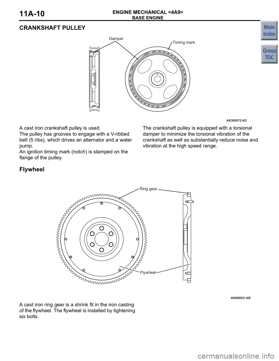
CRANKSHAFT PULLEY
AK305072AD
Timing markDamper
A cast iron cranksh af t pulley is used.
The pulley has grooves to eng age with a V -rib bed
belt (5
ribs), which drives an alternat or and a water
pump
.
An ignition timing mark (notch) is st amp ed on the
flang
e of the pulley .
The crankshaft pulley is equipped with a to rsio nal
damp
e r to minimize the torsional vibratio n of th e
cranksha
f t as well as sub s t antia lly redu ce no ise and
vib
r ation at the high spee d rang e.
Flyw he el
AK600531
Ring gear
Flywheel
AB
A cast iron ring g ear is a shrink fit in th e iron casting
of
t h e f l yw he el. T h e f l yw he el is in st a l le d by tigh t e n i n g
six bolt
s .
Page 60 of 364

BASE ENGINE
ENGINE MECHANICAL <4A9>11A-12
TIMING CHAIN TRAIN
AK305075
V.V.T. sprocket
AB
V.V.T. sprocket
timing mark
Timing chain mark
link plate (bule)
Camshaft sprocket
Camshaft sprocket
timing mark Timing chain mark
link plate (bule)
Timing chain mark
link plate (bule)
Crankshaft
sprocket
timing mark
Crankshaft sprocket
Timing mark
Timing chain
tensioner
Tensioner lever
Chain guide
Timing mark
The 2 camshaf
t s are driven by the t i ming chain via
the res
pec tive spro cke t s .
The timing cha i n, consist i ng o f 122 links, is an end-
less chain, conn ecting the cran ksh af t spro cke t with
the camshaf
t and V . V . T . spro cke t s .
The timing cha i n is eq uippe d with 3 mark link p l ates
(blue)
to co rrectly time t he 3 sprocket s with each
other
.
ItemNo. of
teeth
Camshaft sprocket36
V.V.T. sprocket36
Crankshaft sprocket18
TIMING CHAIN TENSIONER
AK305388AB
Retainer
Ball
Coil spring 1
Ball sheet
Coil spring 2
Cam
Pin
Plunger
The timing chain is tensione
d by th e timing chain te n-
sioner , which ha s a b u ilt-in plunge r with plunge r
springs.
The plunger in the timing chain tension e r dire ctly
push
e s th e tension lever , and the pre s sure aut omati
-
cally ad just s the timing chain tension.
A cam is provided t o lock th e plu nger in pla c e a f te r
the eng
ine stop s. This help s prevent the timing chain
from wob
b lin g just af ter th e eng ine st a r t s .
With the timing cha i n ten s io ner in st alled, do not
crank the
engin e in the reverse directio n. This will
force
the plunger to overcome the cam, or e v en
cause oth
e r problems.
Page 73 of 364

BASE ENGINE
ENGINE MECHANICAL <4A9>11A-25
CRANKSHAFT
AK305068AD
Oil pump drive
gear shaft
Crankshaft
sprocket
Crankshaft sensing ring
CrankshaftOil hole
Oil hole
Balance weightBalance weightBalance weight
A casted crankshaf
t is used for t he cr ankshaf t.
The crankshaft consist s o f 5 ma in be aring s an d 8
balan
ce weight s.
The crankshaft pins a r e arrang ed at 1 8 0° inte rval s.
The oil hole supply lu brication oil from t he jo urnal to
the crank p
i n.
A cranksha f t sprocket and an oil pump drive gea r
shaf
t are press-fit t ed on to the f r ont of the crankshaf t.
The crankshaft is also fitt ed with a crankshaf t sens-
ing ring.
CRANKSHAFT BEARING, THRUST BEARING
AK305070
Upper bearingOil groove
Oil hole
Identification
color
Lower bearing
Identification
color
AB
Thrust bearing
Groove
Front
The upp er cra n kshaf t bea ring (with oil groove) is
loca
ted on the cylinder block side wh ile the lo we r
bearin
g (witho ut oil groo ve) is he ld by the b earin g
cap.
The crankshaft bea ring is e quipp ed with back me t a l.
While the b
earin g it self is ma de of a l uminum alloy ,
the back met
a l is no rmally made of steel sheet .
A thrust bearing is inst alle d on b o th sides of th e No.
4 cran
kshaf t bearing.
ItemDimension
Crankshaft
bearingWidth mm16
Thickness mm20
Crankshaft
thrust bearingThickness mm3.275
Page 74 of 364

BASE ENGINE
ENGINE MECHANICAL <4A9>11A-26
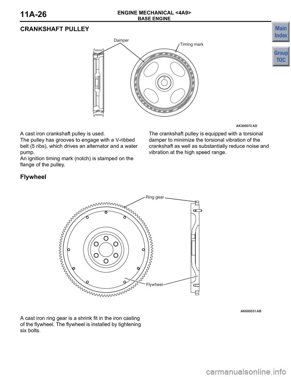
CRANKSHAFT PULLEY
AK305072AD
Timing markDamper
A cast iron cranksh af t pulley is used.
The pulley has grooves to eng age with a V -rib bed
belt (5
ribs), which drives an alternat or and a water
pump
.
An ignition timing mark (notch) is st amp ed on the
flang
e of the pulley .
The crankshaft pulley is equipped with a to rsio nal
damp
e r to minimize the torsional vibratio n of th e
cranksha
f t as well as sub s t antia lly redu ce no ise and
vib
r ation at the high spee d rang e.
Flyw he el
AK600531
Ring gear
Flywheel
AB
A cast iron ring g ear is a shrink fit in th e iron casting
of
t h e f l yw he el. T h e f l yw he el is in st a l le d by tigh t e n i n g
six bolt
s .
Page 76 of 364

BASE ENGINE
ENGINE MECHANICAL <4A9>11A-28
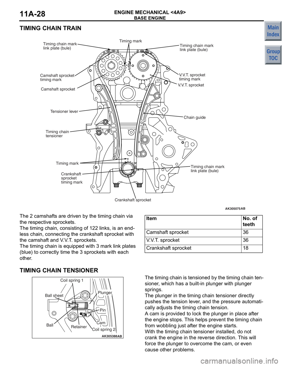
TIMING CHAIN TRAIN
AK305075
V.V.T. sprocket
AB
V.V.T. sprocket
timing mark
Timing chain mark
link plate (bule)
Camshaft sprocket
Camshaft sprocket
timing mark Timing chain mark
link plate (bule)
Timing chain mark
link plate (bule)
Crankshaft
sprocket
timing mark
Crankshaft sprocket
Timing mark
Timing chain
tensioner
Tensioner lever
Chain guide
Timing mark
The 2 camshaf
t s are driven by the t i ming chain via
the res
pec tive spro cke t s .
The timing cha i n, consist i ng o f 122 links, is an end-
less chain, conn ecting the cran ksh af t spro cke t with
the camshaf
t and V . V . T . spro cke t s .
The timing cha i n is eq uippe d with 3 mark link p l ates
(blue)
to co rrectly time t he 3 sprocket s with each
other
.
ItemNo. of
teeth
Camshaft sprocket36
V.V.T. sprocket36
Crankshaft sprocket18
TIMING CHAIN TENSIONER
AK305388AB
Retainer
Ball
Coil spring 1
Ball sheet
Coil spring 2
Cam
Pin
Plunger
The timing chain is tensione
d by th e timing chain te n-
sioner , which ha s a b u ilt-in plunge r with plunge r
springs.
The plunger in the timing chain tension e r dire ctly
push
e s th e tension lever , and the pre s sure aut omati
-
cally ad just s the timing chain tension.
A cam is provided t o lock th e plu nger in pla c e a f te r
the eng
ine stop s. This help s prevent the timing chain
from wob
b lin g just af ter th e eng ine st a r t s .
With the timing cha i n ten s io ner in st alled, do not
crank the
engin e in the reverse directio n. This will
force
the plunger to overcome the cam, or e v en
cause oth
e r problems.
Page 101 of 364

GENERAL INFORMATION
MULTIPOINT FUEL INJECTION (MPI) <4A9>13A-7
Throttle position sensor
and inputs it into the engine-ECU
engine-CVT-ECU
is output by this sensor, the engine-ECU
engine-CVT-ECU
feedback control.
Accelerator pedal position sensor
and inputs it into the engine-ECU
engine-CVT-ECU
is output by this sensor, which determines the
accelerator position (and the intention of the driver),
the engine-ECU
effects appropriate fuel injection and throttle valve
position controls.
Camshaft position sensorThis sensor detects the top-dead-center (TDC) of the
compression stroke of each cylinder.
Crank angle sensorThis sensor detects the crank angle and inputs it into
the engine-ECU
The engine-ECU
effects injector control and other controls in
accordance with the signals received from this
sensor.
Detonation sensorThis sensor, which contains a piezoelectric element,
detects the vibration of the cylinder block that results
from knocking. The engine-ECU
engine-CVT-ECU
of the engine from these vibrations, in order to retard
the ignition timing in accordance with the strength of
the knocks.
Alternator FR terminalThis terminal is used for detecting the duty cycle ratio
that energizes the alternator field coil.
Inhibitor switch
into the engine-CVT-ECU to determine whether the
shift lever is in the neutral position.
Stop lamp switchThis is a contact point type switch that detects how
the brake pedal is depressed.
Actuators
Engine control relayThis relay turns ON and OFF the engine-ECU
or engine-CVT-ECU
Throttle valve control servo relayThis relay turns ON and OFF the actuation power
circuit for the throttle valve control servo in the
engine-ECU
InjectorThe injectors inject fuel in accordance with the
injection signals received from the engine-ECU
Ignition coil (with power transistor)Applies ignition coil primary current intermittently in
accordance with the ignition signals received from
the engine-ECU
in order to generate high voltage for ignition.
Name Function
Page 119 of 364

GENERAL INFORMATION
MULTIPOINT FUEL INJECTION (MPI) <4G1>13B-5
List of Component Functions
ECU
NameFunction
Engine-ECUThe signals that are input by the sensors enable the
actuators to be controlled in accordance with the
driving conditions.
Sensor
Ignition switch-IGThis signal indicates the ON/OFF condition of the
ignition switch. When this signal is input, the
engine-ECU supplies power to the crank angle
sensor, camshaft position sensor, etc.
Ignition switch-STThis signal indicates that the engine is cranking.
Based on this signal, the engine-ECU controls the
fuel injection, throttle valve position, and the injection
timing that are suited for starting the engine.
Air flow sensor This signal, which indicates the intake air flow rate
(mass), is input into the engine-ECU. Based on the
signals from this sensor, the engine-ECU effects fuel
injection control.
Oxygen sensor
electrodes, detects the level of oxygen concentration
in the exhaust gases. The engine-ECU determines
whether the air-fuel ratio is at the optimal
stoichiometric ratio in accordance with this oxygen
concentration level.
Barometric pressure sensorThis sensor detects the altitude of the vehicle. It
enables the engine-ECU to make fuel injection
volume corrections in order to achieve an appropriate
air-fuel ratio.
Intake air temperature sensorThis sensor, which contains a thermistor, detects the
temperature of the intake air. The engine-ECU
makes fuel injection volume corrections that suit the
intake air temperature, in accordance with the
voltage that is output by this sensor.
Engine coolant temperature sensorThis sensor, which contains a thermistor, detects the
temperature of the engine coolant. The engine-ECU
determines the warm-up condition of the engine in
accordance with the voltage that is output by this
sensor, in order to control the fuel injection volume,
idle speed, and ignition timing.
Throttle position sensor
and inputs it into the engine-ECU. Based on the
voltage that is output by this sensor, the engine-ECU
effects throttle valve feedback control.
Accelerator pedal position sensor
and inputs it into the engine-ECU. Based on the
voltage that is output by this sensor, which
determines the accelerator position (and the intention
of the driver), the engine-ECU effects appropriate
fuel injection and throttle valve position controls.