Page 167 of 364
MANUAL TRANSMISSION
MANUAL TRANSMISSION22-2
MANUAL TRANSMISSION
GENERAL INFORMATIONM2220000100592
Due to the addition of vehicles with M/T, a
"GETRAG" F5MG type transmission has been
adopted.
SPECIFICATIONS
Transmission modelF5MGAF5MGB
Engine model4A94G1
Transmission type5-speed, floor-shift
Transmission gear ratio1st3.3083.538
2nd1.9131.913
3rd1.2581.344
4th0.9431.027
5th0.7630.833
Reverse3.2313.357
Final reduction ratio4.1583.737
Transmission fluidSpecified
lubricantsDia-Queen wide gear oil G-1 SAE 75W-90 API GL-4
Quantity L1.75
Page 171 of 364
GENERAL INFORMATION
CLUTCH21-2
GENERAL INFORMATION
M2210000100375
Due to the addition of vehicles with M/T, the dry sin-
gle plate diaphragm spring type is adopted to the
clutch and the hydraulic type is used for control sys
-
tem.
SPECIFICATIONS
ItemSpecification
Transmission modelF5MGAF5MGB
Clutch disc typeDry single plate type
Clutch disc facing diameter OD x ID mm200 × 140216 × 144
Clutch cover typeDiaphragm spring type
Clutch cover setting load N3,600 − 4,1005,400 − 6,000
Control systemHydraulic type
Clutch fluidMitsubishi genuine diamond queen brake fluid super 4
CONSTRUCTION DIAGRAM
AC600647
Clutch pipe assembly A
Clutch pipe assembly B
AB
Reservoir hose Clutch pedal assembly
Clutch release
cylinder Clutch master
cylinder
Page 352 of 364

CVT
CONTINUOUSLY VARIABLE TRANSMISSION (CVT)23-4
DIAGNOSIS CLASSIFICATION TABLE
M2231015000056
ItemDiagnosisData listActuator
test
Code No.Trouble symptomsItem No.Display
Crank angle sensor−−01r/min−
CVT fluid temperature sensor15Open circuit08°C−
16Short circuit
Line pressure sensor18Open circuit09MPa−
19Short circuit
Turbine speed sensor22Open circuit02r/min−
Primary speed sensor23Open circuit03r/min−
26System failure
Secondary speed sensor24Open circuit04r/min−
25System failure
Accelerator pedal position sensor (APS)−−06mV−
Primary pressure sensor27Open circuit11MPa−
28Short circuit
Gear ratio−−12Displays the
gear ratio.−
Line pressure control solenoid valve31Open circuit/short
circuit 16%01
Shift control solenoid valve32Open circuit15%02
36Short circuit
Damper clutch control solenoid valve33Open circuit14%03
37Short circuit
Clutch pressure control solenoid valve34Open circuit17%04
38Short circuit
Shift system42System failure−−−
Damper clutch system44System failure10r/min−
45
Clutch system46System failure−−−
48
Inhibitor switch51Open circuit26P/R/N/D/Ds/L−
52Short circuit
Stop lamp switch53Open circuit33ON/OFF−
54Short circuit
Battery voltage−−24V−
CVT control relay56Open circuit25V11
Steel belt system59System failure−−−
Line pressure system57System failure−−−
71
72
Page 353 of 364

CVT
CONTINUOUSLY VARIABLE TRANSMISSION (CVT)23-5
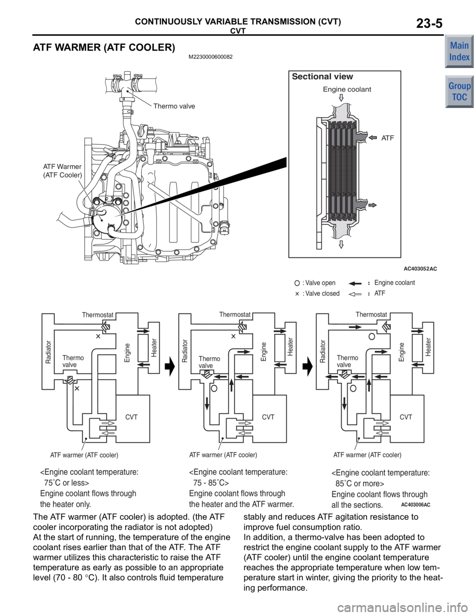
ATF WARMER (ATF COOLER)
M2230000600082
AC403052AC
AT F
Engine coolant
Sectional view
ATF Warmer
(ATF Cooler)
Thermo valve
AC403006
CVT CVT CVT
Thermostat
Thermo
valve
ATF warmer (ATF cooler)ATF warmer (ATF cooler)
: Engine coolant
: AT F
85˚C or more>
Engine coolant flows through
all the sections.
75 - 85˚C>
Engine coolant flows through
the heater and the ATF warmer.
75˚C or less>
Engine coolant flows through
the heater only.
AC
: Valve open
: Valve closed
Thermostat
Thermo
valve
ATF warmer (ATF cooler)Thermo
valve
Thermostat
Radiator
Engine Heater
Radiator Engine Heater
Radiator
Engine Heater
The A TF warme r (A TF cooler) is adop ted. (th e A TF
cooler in
corpo r ating the rad i ator is n o t ado pted)
At the st art of runn ing, th e tempe r ature of th e engine
coolant rises earlier tha
n that of the A T F . The A TF
war
m er ut ilizes this ch aract e ristic to raise the A TF
tempe
r ature a s ea rly a s po ssible to an a ppropriate
leve
l (70 - 80
°C). It also contro ls fluid temperature st ably and reduces A TF agit a tion resist ance to
imp r ove f uel consump t ion ra tio.
In addition
, a the r mo-valve has bee n adop ted to
restrict the eng
ine coolan t supply to the A TF warmer
(A
TF coole r) until the engine co olan t temperature
reach
e s th e appro p riat e temperature when low tem
-
perature st art in winter , giving the priority to th e heat-
ing pe rformance .