2006 MERCEDES-BENZ SPRINTER airbag disable
[x] Cancel search: airbag disablePage 2012 of 2305
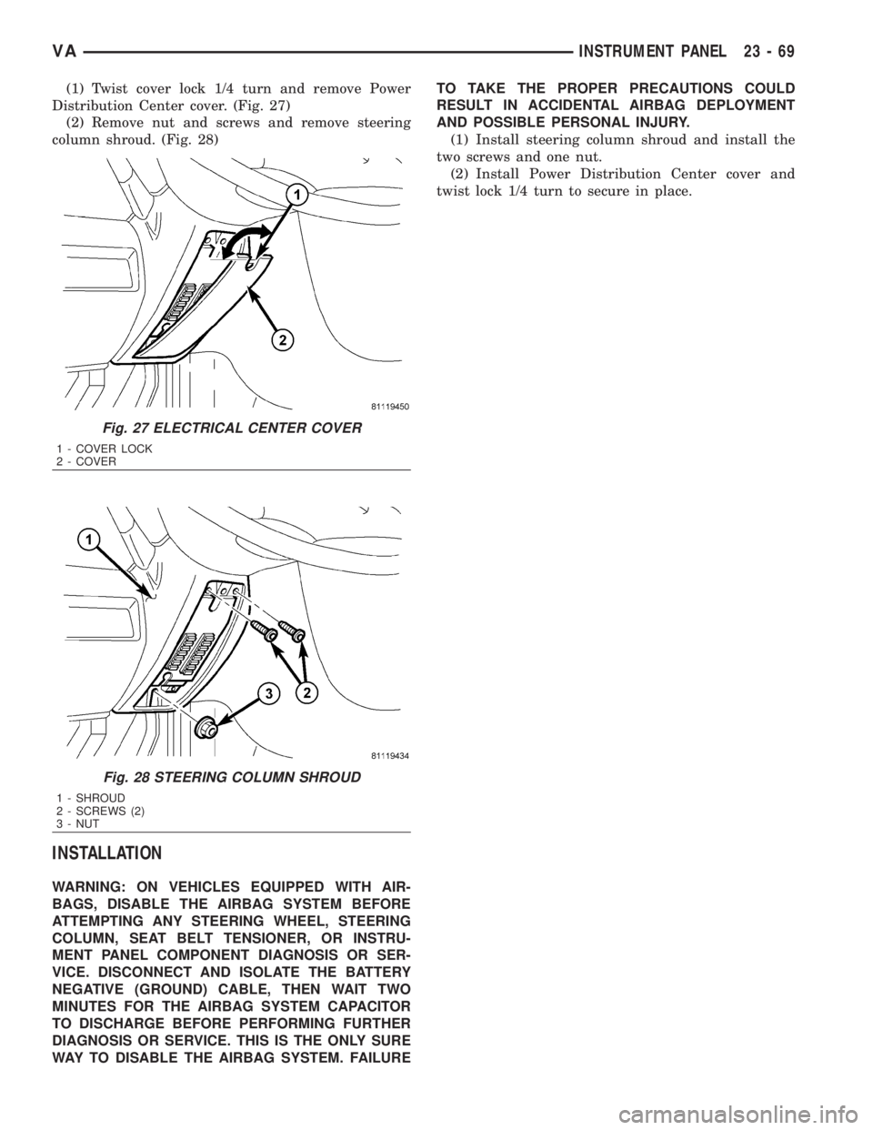
(1) Twist cover lock 1/4 turn and remove Power
Distribution Center cover. (Fig. 27)
(2) Remove nut and screws and remove steering
column shroud. (Fig. 28)
INSTALLATION
WARNING: ON VEHICLES EQUIPPED WITH AIR-
BAGS, DISABLE THE AIRBAG SYSTEM BEFORE
ATTEMPTING ANY STEERING WHEEL, STEERING
COLUMN, SEAT BELT TENSIONER, OR INSTRU-
MENT PANEL COMPONENT DIAGNOSIS OR SER-
VICE. DISCONNECT AND ISOLATE THE BATTERY
NEGATIVE (GROUND) CABLE, THEN WAIT TWO
MINUTES FOR THE AIRBAG SYSTEM CAPACITOR
TO DISCHARGE BEFORE PERFORMING FURTHER
DIAGNOSIS OR SERVICE. THIS IS THE ONLY SURE
WAY TO DISABLE THE AIRBAG SYSTEM. FAILURETO TAKE THE PROPER PRECAUTIONS COULD
RESULT IN ACCIDENTAL AIRBAG DEPLOYMENT
AND POSSIBLE PERSONAL INJURY.
(1) Install steering column shroud and install the
two screws and one nut.
(2) Install Power Distribution Center cover and
twist lock 1/4 turn to secure in place.
Fig. 27 ELECTRICAL CENTER COVER
1 - COVER LOCK
2 - COVER
Fig. 28 STEERING COLUMN SHROUD
1 - SHROUD
2 - SCREWS (2)
3 - NUT
VAINSTRUMENT PANEL 23 - 69
Page 2050 of 2305
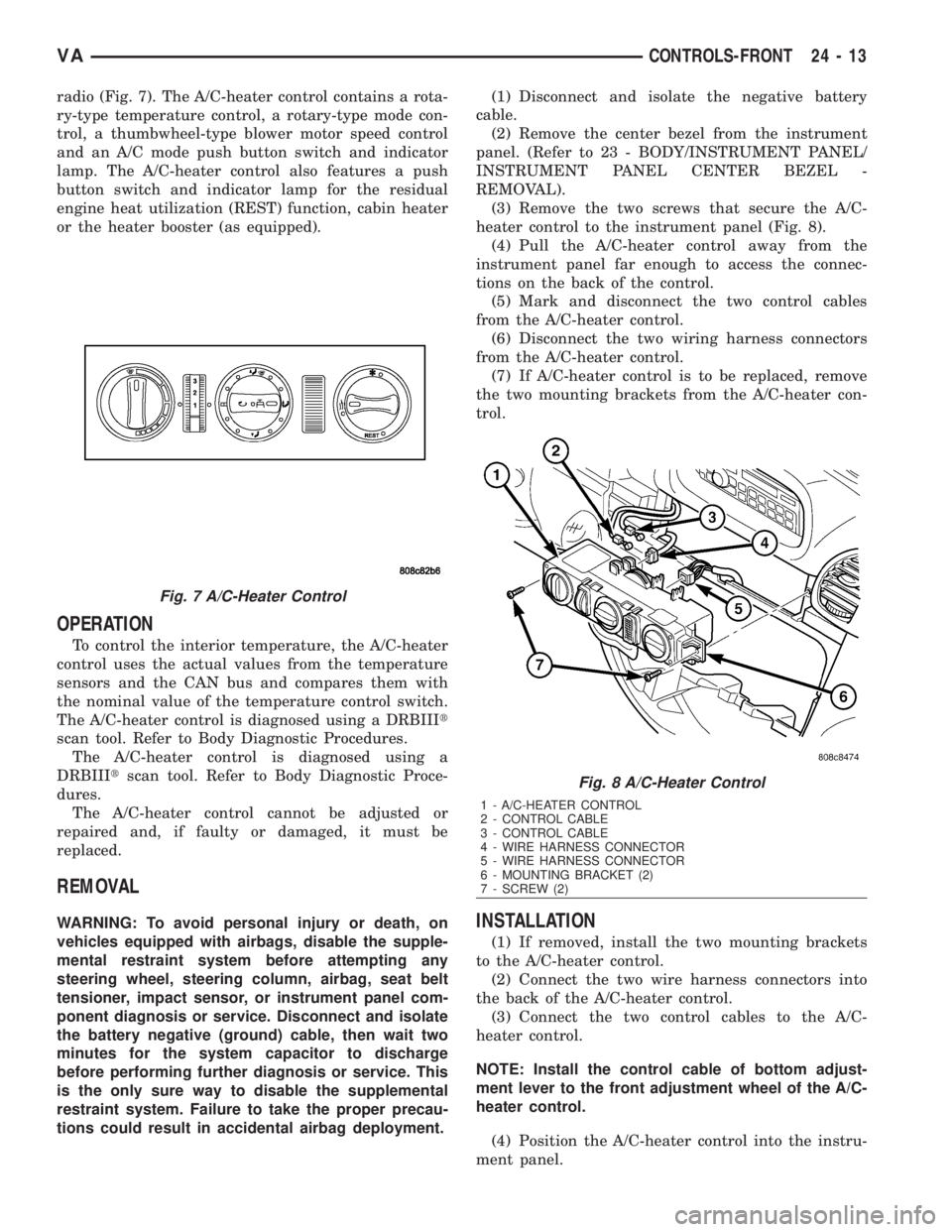
radio (Fig. 7). The A/C-heater control contains a rota-
ry-type temperature control, a rotary-type mode con-
trol, a thumbwheel-type blower motor speed control
and an A/C mode push button switch and indicator
lamp. The A/C-heater control also features a push
button switch and indicator lamp for the residual
engine heat utilization (REST) function, cabin heater
or the heater booster (as equipped).
OPERATION
To control the interior temperature, the A/C-heater
control uses the actual values from the temperature
sensors and the CAN bus and compares them with
the nominal value of the temperature control switch.
The A/C-heater control is diagnosed using a DRBIIIt
scan tool. Refer to Body Diagnostic Procedures.
The A/C-heater control is diagnosed using a
DRBIIItscan tool. Refer to Body Diagnostic Proce-
dures.
The A/C-heater control cannot be adjusted or
repaired and, if faulty or damaged, it must be
replaced.
REMOVAL
WARNING: To avoid personal injury or death, on
vehicles equipped with airbags, disable the supple-
mental restraint system before attempting any
steering wheel, steering column, airbag, seat belt
tensioner, impact sensor, or instrument panel com-
ponent diagnosis or service. Disconnect and isolate
the battery negative (ground) cable, then wait two
minutes for the system capacitor to discharge
before performing further diagnosis or service. This
is the only sure way to disable the supplemental
restraint system. Failure to take the proper precau-
tions could result in accidental airbag deployment.(1) Disconnect and isolate the negative battery
cable.
(2) Remove the center bezel from the instrument
panel. (Refer to 23 - BODY/INSTRUMENT PANEL/
INSTRUMENT PANEL CENTER BEZEL -
REMOVAL).
(3) Remove the two screws that secure the A/C-
heater control to the instrument panel (Fig. 8).
(4) Pull the A/C-heater control away from the
instrument panel far enough to access the connec-
tions on the back of the control.
(5) Mark and disconnect the two control cables
from the A/C-heater control.
(6) Disconnect the two wiring harness connectors
from the A/C-heater control.
(7) If A/C-heater control is to be replaced, remove
the two mounting brackets from the A/C-heater con-
trol.INSTALLATION
(1) If removed, install the two mounting brackets
to the A/C-heater control.
(2) Connect the two wire harness connectors into
the back of the A/C-heater control.
(3) Connect the two control cables to the A/C-
heater control.
NOTE: Install the control cable of bottom adjust-
ment lever to the front adjustment wheel of the A/C-
heater control.
(4) Position the A/C-heater control into the instru-
ment panel.
Fig. 7 A/C-Heater Control
Fig. 8 A/C-Heater Control
1 - A/C-HEATER CONTROL
2 - CONTROL CABLE
3 - CONTROL CABLE
4 - WIRE HARNESS CONNECTOR
5 - WIRE HARNESS CONNECTOR
6 - MOUNTING BRACKET (2)
7 - SCREW (2)
VACONTROLS-FRONT 24 - 13
Page 2073 of 2305
motor, while relay 2 when activated, sends power
directly to the blower motor.
The rear blower motor switch cannot be repaired
and, if faulty or damaged, it must be replaced.
DIAGNOSIS AND TESTING
REAR BLOWER MOTOR SWITCH
Before testing the rear blower motor switch, verify
that the front A/C system is functional by performing
the ATC Fuction Test using the DRBIIItscan tool.
Use a volt/ohmmeter to test the rear blower motor
switch. For circuit descriptions and diagrams, refer
to the appropriate wiring information. The wiring
information includes wiring diagrams, proper wire
and connector repair procedures, details of wire har-
ness routing and retention, connector pin-out infor-
mation and location views for the various wire
harness connectors, splices and grounds.
WARNING: To avoid personal injury or death, on
vehicles equipped with airbags, disable the supple-
mental restraint system before attempting any
steering wheel, steering column, airbag, seat belt
tensioner, impact sensor, or instrument panel com-
ponent diagnosis or service. Disconnect and isolate
the battery negative (ground) cable, then wait two
minutes for the system capacitor to discharge
before performing further diagnosis or service. This
is the only sure way to disable the supplemental
restraint system. Failure to take the proper precau-
tions could result in accidental airbag deployment.
(1) Disconnect and isolate the battery negative
cable.
(2) Unplug the wire harness connector from the
rear blower motor switch.
(3) Check for continuity between terminal 10 and
terminals 1, 7 and 4 of the blower motor switch. In
all instances, there should be continuity.
NOTE: To check the switch's internal circuits, con-
nect the negative lead of the ohmmeter to terminal
10 and the positive ohmmeter lead to terminals 1, 7
and 4. To check the switch's integral light emitting
diodes, reverse the ohmmeter leads.
(4) Check for continuity between the rear blower
motor switch terminals 3 and 7 as you move the
blower motor switch to each of the two speed posi-
tions, and the Off position. There should be continu-
ity in only one blower motor switch speed position.
(5) Check for continuity between the rear blower
motor switch terminals 4 and 8 as you move the
blower motor switch to each of the two speed posi-
tions, and the Off position. There should be continu-ity in only the other blower motor switch speed
position.
(6) If OK, test and repair the rear blower motor
switch wire harness circuits. If not OK, replace the
faulty rear blower motor switch.
REMOVAL
WARNING: To avoid personal injury or death, on
vehicles equipped with airbags, disable the supple-
mental restraint system before attempting any
steering wheel, steering column, airbag, seat belt
tensioner, impact sensor, or instrument panel com-
ponent diagnosis or service. Disconnect and isolate
the battery negative (ground) cable, then wait two
minutes for the system capacitor to discharge
before performing further diagnosis or service. This
is the only sure way to disable the supplemental
restraint system. Failure to take the proper precau-
tions could result in accidental airbag deployment.
NOTE: The rear A/C blower motor switch is used on
vehicles with the optional rear A/C system.
(1) Disconnect and isolate the negative battery
cable.
(2) Remove the accessory switch panel from the
instrument panel (Refer to 23 - BODY/INSTRU-
MENT PANEL/ACCESSORY SWITCH BEZEL -
REMOVAL).
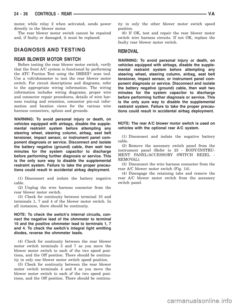
(3) Disconnect the wire harness connector from the
rear A/C blower motor switch (Fig. 14).
(4) Disengage the retaining tabs and remove the
rear A/C blower motor switch from the accessory
switch panel.
24 - 36 CONTROLS - REARVA
Page 2076 of 2305
rear A/C control module. The temperature of the cir-
culated internal air of the rear compartment is mea-
sured by a temperature sensor located in the rear
evaporator unit. The value of the temperature sensor
is compared in the rear A/C control module with an
adjusted value at the rear A/C temperature control.
The rear A/C temperature control cannot be
repaired and, if faulty or damaged, it must be
replaced.
DIAGNOSIS AND TESTING
REARA/CTEMPERATURE CONTROL
Before testing the rear A/C temperature control,
verify that the front A/C system is operating correctly
by performing the ATC Function Test using the
DRBIIItscan tool. Use a volt/ohmmeter to test the
control. For circuit descriptions and diagrams, refer
to the appropriate wiring information. The wiring
information includes wiring diagrams, proper wire
and connector repair procedures, details of wire har-
ness routing and retention, connector pin-out infor-
mation and location views for the various wire
harness connectors, splices and grounds.
WARNING: To avoid personal injury or death, on
vehicles equipped with airbags, disable the supple-
mental restraint system before attempting any
steering wheel, steering column, airbag, seat belt
tensioner, impact sensor, or instrument panel com-
ponent diagnosis or service. Disconnect and isolate
the battery negative (ground) cable, then wait two
minutes for the system capacitor to discharge
before performing further diagnosis or service. This
is the only sure way to disable the supplemental
restraint system. Failure to take the proper precau-
tions could result in accidental airbag deployment.
(1) Disconnect and isolate the battery negative
cable.
(2) Unplug the wire harness connector from the
rear A/C temperature control.
(3) Check for continuity between terminal 9 and
terminals 3 and 5 of the A/C temperature control. In
all instances, there should be continuity.
NOTE: To check the switch's internal circuits, con-
nect the positive lead of the ohmmeter to terminal 9
and the negative lead to terminals 3 and 5. To
check the switches integral light emitting diode,
reverse the ohmmeter leads.
(4) Check for resistance between terminal 3 and 5
of the A/C temperature control as you move the con-
trol to each temperature position. Resistance should
be present and should change for each position.(5) If OK, test and repair the rear A/C tempera-
ture control wire harness circuits. If not OK, replace
the faulty rear A/C temperature control.
REMOVAL
WARNING: To avoid personal injury or death, on
vehicles equipped with airbags, disable the supple-
mental restraint system before attempting any
steering wheel, steering column, airbag, seat belt
tensioner, impact sensor, or instrument panel com-
ponent diagnosis or service. Disconnect and isolate
the battery negative (ground) cable, then wait two
minutes for the system capacitor to discharge
before performing further diagnosis or service. This
is the only sure way to disable the supplemental
restraint system. Failure to take the proper precau-
tions could result in accidental airbag deployment.
NOTE: The rear A/C temperature control is used
only on models with the optional rear A/C unit.
(1) Disconnect and isolate the negative battery
cable.
(2) Remove the accessory switch panel from the
instrument panel (Refer to 23 - BODY/INSTRU-
MENT PANEL/ACCESSORY SWITCH BEZEL -
REMOVAL).
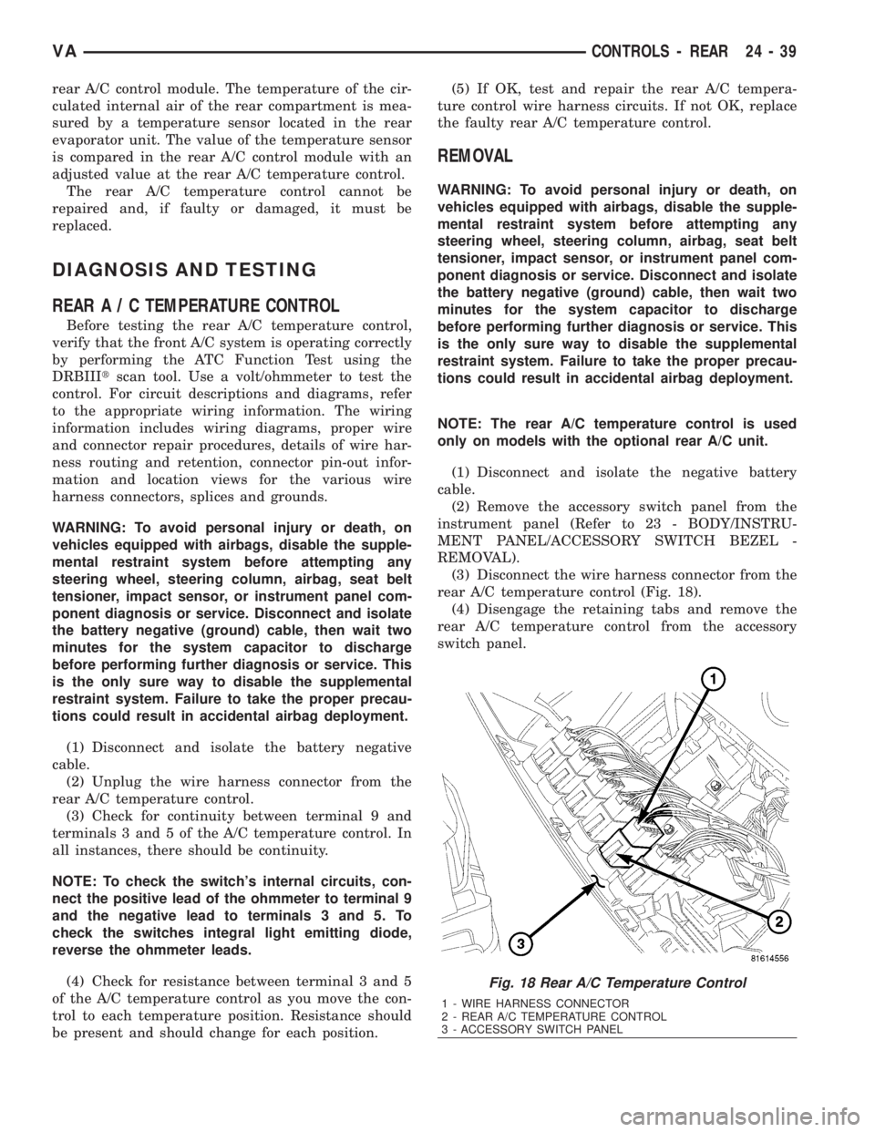
(3) Disconnect the wire harness connector from the
rear A/C temperature control (Fig. 18).
(4) Disengage the retaining tabs and remove the
rear A/C temperature control from the accessory
switch panel.
Fig. 18 Rear A/C Temperature Control
1 - WIRE HARNESS CONNECTOR
2 - REAR A/C TEMPERATURE CONTROL
3 - ACCESSORY SWITCH PANEL
VACONTROLS - REAR 24 - 39
Page 2082 of 2305
DISTRIBUTION - FRONT
TABLE OF CONTENTS
page page
AIR FILTER
REMOVAL.............................45
INSTALLATION.........................45
AIR OUTLETS
REMOVAL.............................45
INSTALLATION.........................46
BLOWER MOTOR
REMOVAL.............................47
INSTALLATION.........................47
DEFROSTER DUCTS
REMOVAL.............................47
INSTALLATION.........................47FLOOR DISTRIBUTION DUCTS
REMOVAL.............................47
INSTALLATION.........................48
HVAC HOUSING
REMOVAL.............................48
DISASSEMBLY.........................49
ASSEMBLY............................50
INSTALLATION.........................50
INSTRUMENT PANEL DUCTS
REMOVAL.............................51
INSTALLATION.........................51
AIR FILTER
REMOVAL
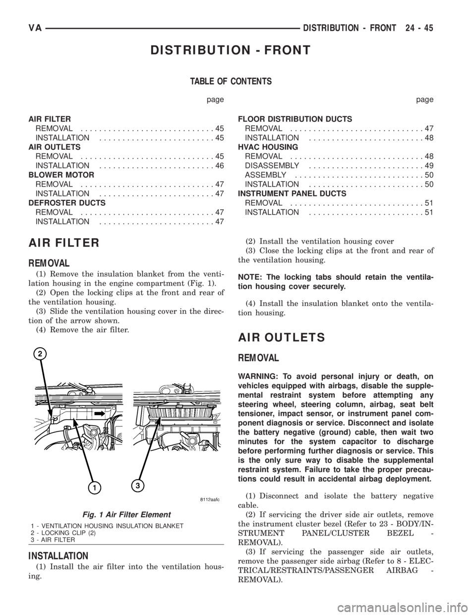
(1) Remove the insulation blanket from the venti-
lation housing in the engine compartment (Fig. 1).
(2) Open the locking clips at the front and rear of
the ventilation housing.
(3) Slide the ventilation housing cover in the direc-
tion of the arrow shown.
(4) Remove the air filter.
INSTALLATION
(1) Install the air filter into the ventilation hous-
ing.(2) Install the ventilation housing cover
(3) Close the locking clips at the front and rear of
the ventilation housing.
NOTE: The locking tabs should retain the ventila-
tion housing cover securely.
(4) Install the insulation blanket onto the ventila-
tion housing.
AIR OUTLETS
REMOVAL
WARNING: To avoid personal injury or death, on
vehicles equipped with airbags, disable the supple-
mental restraint system before attempting any
steering wheel, steering column, airbag, seat belt
tensioner, impact sensor, or instrument panel com-
ponent diagnosis or service. Disconnect and isolate
the battery negative (ground) cable, then wait two
minutes for the system capacitor to discharge
before performing further diagnosis or service. This
is the only sure way to disable the supplemental
restraint system. Failure to take the proper precau-
tions could result in accidental airbag deployment.
(1) Disconnect and isolate the battery negative
cable.
(2) If servicing the driver side air outlets, remove
the instrument cluster bezel (Refer to 23 - BODY/IN-
STRUMENT PANEL/CLUSTER BEZEL -
REMOVAL).
(3) If servicing the passenger side air outlets,
remove the passenger side airbag (Refer to 8 - ELEC-
TRICAL/RESTRAINTS/PASSENGER AIRBAG -
REMOVAL).
Fig. 1 Air Filter Element
1 - VENTILATION HOUSING INSULATION BLANKET
2 - LOCKING CLIP (2)
3 - AIR FILTER
VADISTRIBUTION - FRONT 24 - 45
Page 2085 of 2305
(5) Remove the shift mechanism (Refer to 21 -
TRANSMISSION/TRANSAXLE/AUTOMATIC -
NAG1/SHIFT MECHANISM - REMOVAL).
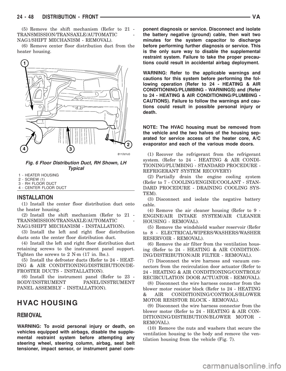
(6) Remove center floor distribution duct from the
heater housing.
INSTALLATION
(1) Install the center floor distribution duct onto
the heater housing.
(2) Install the shift mechanism (Refer to 21 -
TRANSMISSION/TRANSAXLE/AUTOMATIC -
NAG1/SHIFT MECHANISM - INSTALLATION).
(3) Install the left and right floor distribution
ducts onto the center floor distribution duct.
(4) Install the left and right floor distribution duct
retaining screws to the instrument panel support.
Tighten the screws to 2 N´m (17 in. lbs.).
(5) Install the defroster ducts (Refer to 24 - HEAT-
ING & AIR CONDITIONING/DISTRIBUTION/DE-
FROSTER DUCTS - INSTALLATION).
(6) Install the instrument panel (Refer to 23 -
BODY/INSTRUMENT PANEL/INSTRUMENT
PANEL ASSEMBLY - INSTALLATION).
HVAC HOUSING
REMOVAL
WARNING: To avoid personal injury or death, on
vehicles equipped with airbags, disable the supple-
mental restraint system before attempting any
steering wheel, steering column, airbag, seat belt
tensioner, impact sensor, or instrument panel com-ponent diagnosis or service. Disconnect and isolate
the battery negative (ground) cable, then wait two
minutes for the system capacitor to discharge
before performing further diagnosis or service. This
is the only sure way to disable the supplemental
restraint system. Failure to take the proper precau-
tions could result in accidental airbag deployment.
WARNING: Refer to the applicable warnings and
cautions for this system before performing the fol-
lowing operation (Refer to 24 - HEATING & AIR
CONDITIONING/PLUMBING - WARNINGS) and (Refer
to 24 - HEATING & AIR CONDITIONING/PLUMBING -
CAUTIONS). Failure to follow the warnings and cau-
tions could result in possible personal injury or
death.
NOTE: The HVAC housing must be removed from
the vehicle and the two halves of the housing sep-
arated for service access of the heater core, A/C
evaporator and each of the various mode doors.
(1) Recover the refrigerant from the refrigerant
system. (Refer to 24 - HEATING & AIR CONDI-
TIONING/PLUMBING - STANDARD PROCEDURE -
REFRIGERANT SYSTEM RECOVERY)
(2) Partially drain the engine cooling system
(Refer to 7 - COOLING/ENGINE/COOLANT - STAN-
DARD PROCEDURE - DRAINING COOLING SYS-
TEM).
(3) Disconnect and isolate the negative battery
cable.
(4) Remove the air cleaner housing (Refer to 9 -
ENGINE/AIR INTAKE SYSTEM/AIR CLEANER
HOUSING - REMOVAL).
(5) Remove the windshield washer reservoir (Refer
to 8 - ELECTRICAL/WIPERS/WASHERS/WASHER
RESERVOIR - REMOVAL).
(6) Remove the air filter from the ventilation hous-
ing (Refer to 24 - HEATING & AIR CONDITION-
ING/DISTRIBUTION/AIR FILTER - REMOVAL).
(7) Disconnect the wire harness and vacuum con-
nectors from the recirculation door actuator (Refer to
24 - HEATING & AIR CONDITIONING/CONTROLS/
RECIRCULATION DOOR ACTUATOR - REMOVAL).
(8) Disconnect the wire harness connector from the
blower motor resistor block (Refer to 24 - HEATING
& AIR CONDITIONING/CONTROLS/BLOWER
MOTOR RESISTOR BLOCK - REMOVAL).
(9) Disconnect the wire harness connector from the
blower motor (Refer to 24 - HEATING & AIR CON-
DITIONING/DISTRIBUTION/BLOWER MOTOR -
REMOVAL).
(10) Remove the nuts and washers that secure the
ventilation housing to the body and remove the ven-
tilation housing from the vehicle (Fig. 7).
Fig. 6 Floor Distribution Duct, RH Shown, LH
Typical
1 - HEATER HOUSING
2 - SCREW (1)
3 - RH FLOOR DUCT
4 - CENTER FLOOR DUCT
24 - 48 DISTRIBUTION - FRONTVA
Page 2109 of 2305
(6) Remove the tape or plugs from the condenser
inlet port and the discharge line fitting.
(7) Lubricate a new rubber O-ring seal with clean
refrigerant oil and install it on the discharge line fit-
ting.
(8) Connect the discharge line fitting to the con-
denser inlet port.
(9) Install the nut that secures the discharge line
fitting to the condenser. Tighten the nut to 33 N´m
(24 ft. lbs.).
(10) Install the grille (Refer to 23 - BODY/EXTE-
RIOR/GRILLE - INSTALLATION).
(11) Evacuate the refrigerant system. (Refer to 24 -
HEATING & AIR CONDITIONING/PLUMBING -
STANDARD PROCEDURE - REFRIGERANT SYS-
TEM EVACUATE)
(12) Charge the refrigerant system. (Refer to 24 -
HEATING & AIR CONDITIONING/PLUMBING -
STANDARD PROCEDURE - REFRIGERANT SYS-
TEM CHARGE)
(13) Reconnect the negative battery cable.
A/CEVAPORATOR
DESCRIPTION
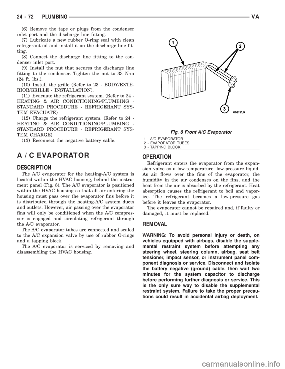
The A/C evaporator for the heating-A/C system is
located within the HVAC housing, behind the instru-
ment panel (Fig. 8). The A/C evaporator is positioned
within the HVAC housing so that all air entering the
housing must pass over the evaporator fins before it
is distributed through the heating-A/C system ducts
and outlets. However, air passing over the evaporator
fins will only be conditioned when the A/C compres-
sor is engaged and circulating refrigerant through
the A/C evaporator.
The A/C evaporator tubes are connected and sealed
to the A/C expansion valve by use of rubber O-rings
and a tapping block.
The A/C evaporator is serviced by removing and
disassembling the HVAC housing.
OPERATION
Refrigerant enters the evaporator from the expan-
sion valve as a low-temperature, low-pressure liquid.
As air flows over the fins of the evaporator, the
humidity in the air condenses on the fins, and the
heat from the air is absorbed by the refrigerant. Heat
absorption causes the refrigerant to boil and vapor-
ize. The refrigerant becomes a low-pressure gas
before it leaves the evaporator.
The evaporator cannot be repaired and, if faulty or
damaged, it must be replaced.
REMOVAL
WARNING: To avoid personal injury or death, on
vehicles equipped with airbags, disable the supple-
mental restraint system before attempting any
steering wheel, steering column, airbag, seat belt
tensioner, impact sensor, or instrument panel com-
ponent diagnosis or service. Disconnect and isolate
the battery negative (ground) cable, then wait two
minutes for the system capacitor to discharge
before performing further diagnosis or service. This
is the only sure way to disable the supplemental
restraint system. Failure to take the proper precau-
tions could result in accidental airbag deployment.
Fig. 8 Front A/C Evaporator
1 - A/C EVAPORATOR
2 - EVAPORATOR TUBES
3 - TAPPING BLOCK
24 - 72 PLUMBINGVA
Page 2113 of 2305
INSTALLATION
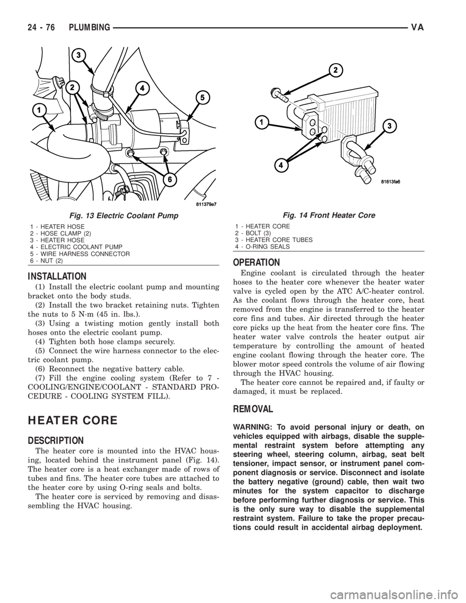
(1) Install the electric coolant pump and mounting
bracket onto the body studs.
(2) Install the two bracket retaining nuts. Tighten
the nuts to 5 N´m (45 in. lbs.).
(3) Using a twisting motion gently install both
hoses onto the electric coolant pump.
(4) Tighten both hose clamps securely.
(5) Connect the wire harness connector to the elec-
tric coolant pump.
(6) Reconnect the negative battery cable.
(7) Fill the engine cooling system (Refer to 7 -
COOLING/ENGINE/COOLANT - STANDARD PRO-
CEDURE - COOLING SYSTEM FILL).
HEATER CORE
DESCRIPTION
The heater core is mounted into the HVAC hous-
ing, located behind the instrument panel (Fig. 14).
The heater core is a heat exchanger made of rows of
tubes and fins. The heater core tubes are attached to
the heater core by using O-ring seals and bolts.
The heater core is serviced by removing and disas-
sembling the HVAC housing.
OPERATION
Engine coolant is circulated through the heater
hoses to the heater core whenever the heater water
valve is cycled open by the ATC A/C-heater control.
As the coolant flows through the heater core, heat
removed from the engine is transferred to the heater
core fins and tubes. Air directed through the heater
core picks up the heat from the heater core fins. The
heater water valve controls the heater output air
temperature by controlling the amount of heated
engine coolant flowing through the heater core. The
blower motor speed controls the volume of air flowing
through the HVAC housing.
The heater core cannot be repaired and, if faulty or
damaged, it must be replaced.
REMOVAL
WARNING: To avoid personal injury or death, on
vehicles equipped with airbags, disable the supple-
mental restraint system before attempting any
steering wheel, steering column, airbag, seat belt
tensioner, impact sensor, or instrument panel com-
ponent diagnosis or service. Disconnect and isolate
the battery negative (ground) cable, then wait two
minutes for the system capacitor to discharge
before performing further diagnosis or service. This
is the only sure way to disable the supplemental
restraint system. Failure to take the proper precau-
tions could result in accidental airbag deployment.
Fig. 13 Electric Coolant Pump
1 - HEATER HOSE
2 - HOSE CLAMP (2)
3 - HEATER HOSE
4 - ELECTRIC COOLANT PUMP
5 - WIRE HARNESS CONNECTOR
6 - NUT (2)
Fig. 14 Front Heater Core
1 - HEATER CORE
2 - BOLT (3)
3 - HEATER CORE TUBES
4 - O-RING SEALS
24 - 76 PLUMBINGVA