2006 MERCEDES-BENZ SPRINTER engine
[x] Cancel search: enginePage 1528 of 2305
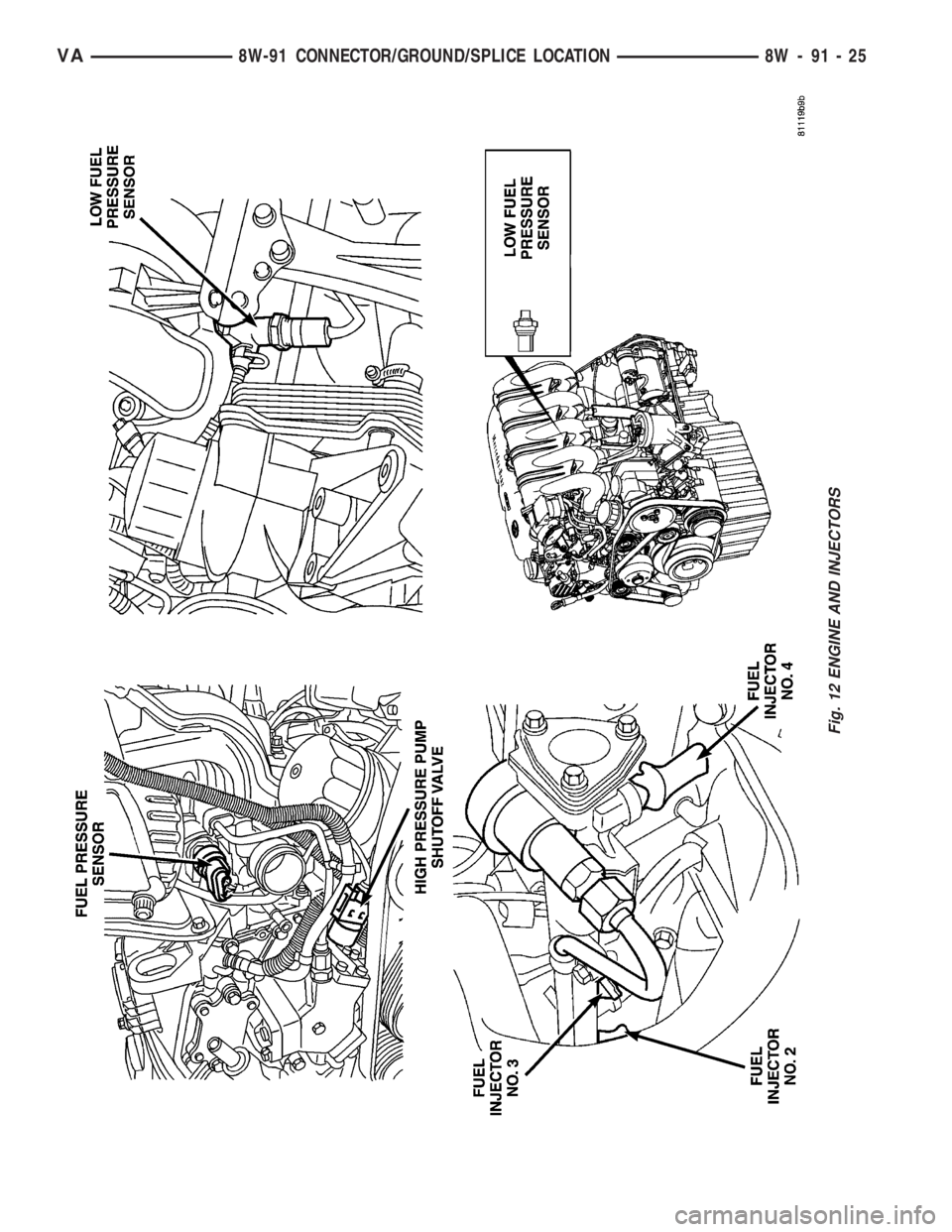
Fig. 12 ENGINE AND INJECTORS
VA8W-91 CONNECTOR/GROUND/SPLICE LOCATION 8W - 91 - 25
Page 1529 of 2305
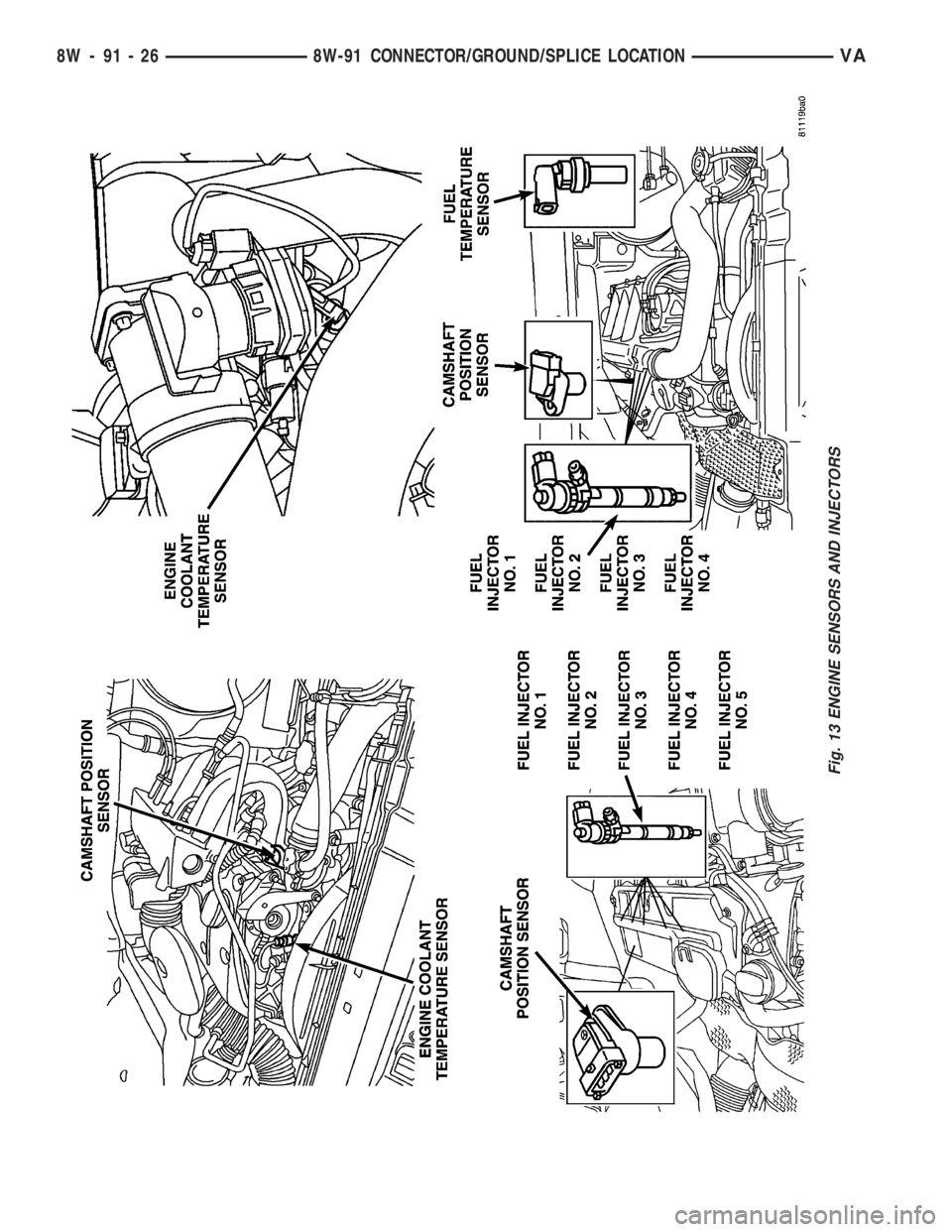
Fig. 13 ENGINE SENSORS AND INJECTORS
8W - 91 - 26 8W-91 CONNECTOR/GROUND/SPLICE LOCATIONVA
Page 1530 of 2305
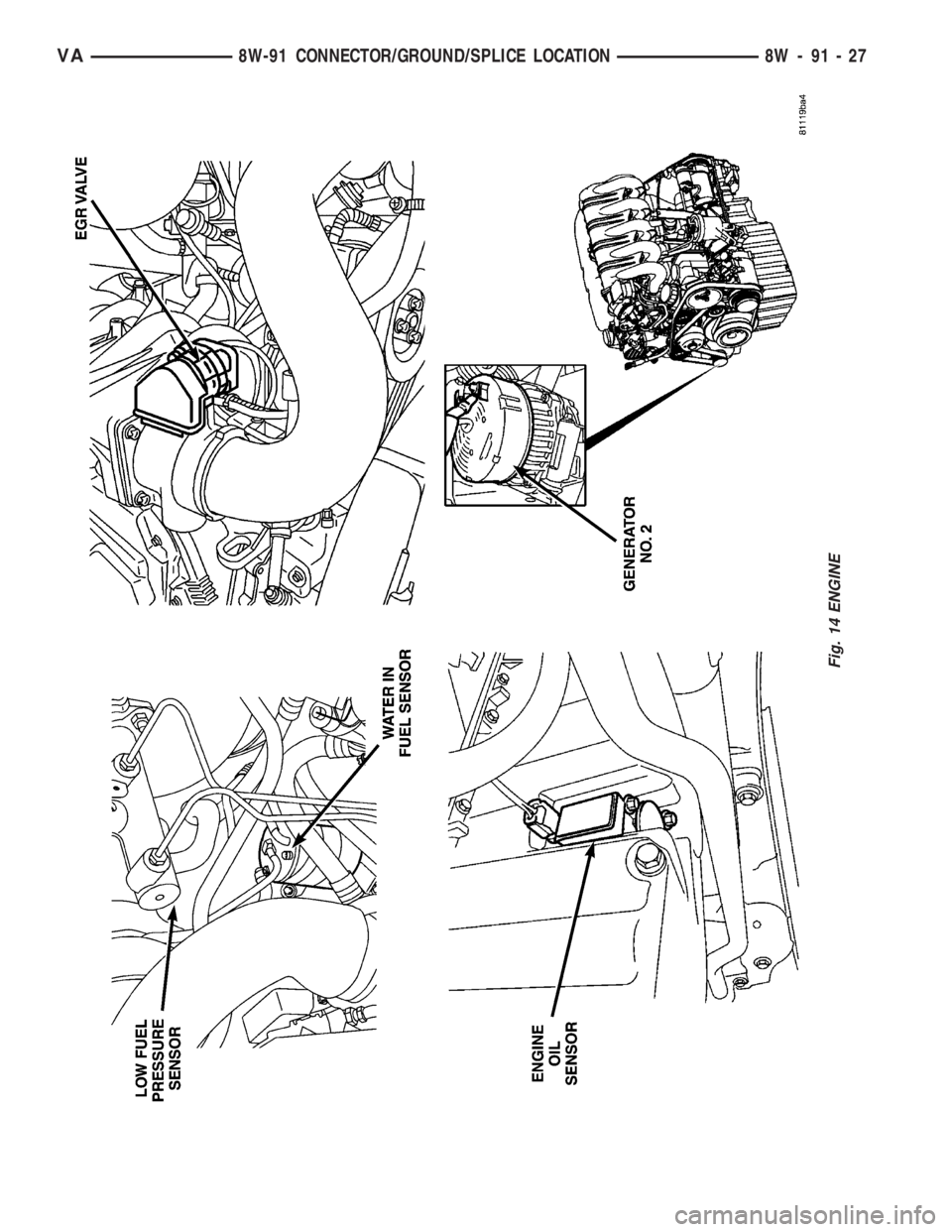
Fig. 14 ENGINE
VA8W-91 CONNECTOR/GROUND/SPLICE LOCATION 8W - 91 - 27
Page 1531 of 2305
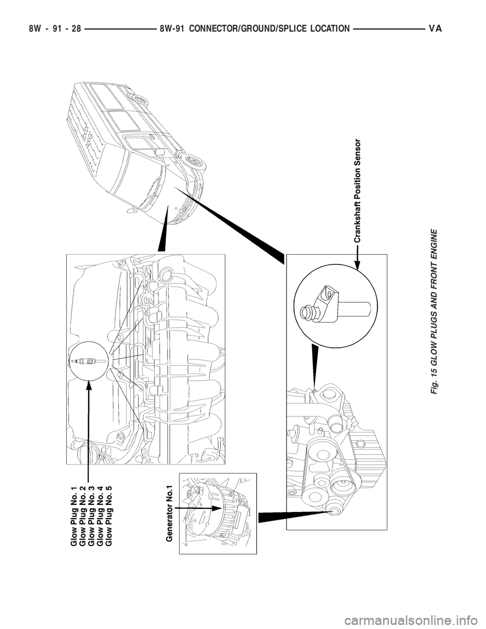
Fig. 15 GLOW PLUGS AND FRONT ENGINE
8W - 91 - 28 8W-91 CONNECTOR/GROUND/SPLICE LOCATIONVA
Page 1572 of 2305
OPERATION
All of the circuits entering and leaving the fuse
block do so through the instrument panel wire har-
ness. Internal connection of all of the fuse block cir-
cuits is accomplished by an intricate combination of
hard wiring and bus bars. Internal relays and micro
processors allow the vehicle electronics to control
some of the power distribution circuits throughout
the vehicle. Refer to the Wiring section for complete
circuit diagrams.
REMOVAL
(1) Disconnect and isolate the negative battery
cable.
(2) Remove fuse block cover by rotating locking
screw 90É.
(3) Remove the steering column cover. Refer to the
Body section for the procedure.
(4) Unscrew fuse block connections and disconnect
all electrical connectors from the fuse block.
(5) Remove the fuse block from the steering col-
umn.
INSTALLATION
(1) Position the fuse block in the steering column.
(2) Install fuse block connections and connect all
electrical connectors on the fuse block.
(3) Install the steering column cover. Refer to the
Body section for the procedure.
(4) Install fuse block cover by rotating locking
screw 90É.
(5) Connect the negative battery cable.
(6) Set time and radio stations.
FUSE BLOCK #2
DESCRIPTION
An electrical fuse block is concealed under the
driver side front seat. The fuse block serves to dis-
tribute electrical current to many of the electrical
systems in the vehicle. The fuse block houses blade-
type mini fuses, blade-type automatic resetting cir-
cuit breakers and International Standards
Organization relays. Additional provisions are avail-
able in the fuse block for additional fuses and ISO
relays.
The molded plastic fuse block housing has an inte-
gral mounting bracket that is secured with screws to
the seat base. The driver side seat base also has a
snap-fit fuse access panel that can be removed for
service of the fuses and the relays. A finger recess is
molded into one end for easy removal. A fuse layout
map is molded onto the back side of the panel to
ensure proper fuse identification.
The fuse block is integral to the body wire harness.
If any internal circuit or the fuse block housing isfaulty or damaged, the entire fuse block and body
wire harness unit must be replaced.
OPERATION
All of the circuits entering and leaving the fuse
block do so through the body wire harness. Internal
connection of all of the fuse block circuits is accom-
plished by an intricate combination of hard wiring
and bus bars.
POWER DISTRIBUTION CEN-
TER
DESCRIPTION
All of the electrical current distributed throughout
this vehicle is directed through the Power Distribu-
tion Center (PDC). The molded plastic PDC housing
is located in the left front corner of the engine com-
partment, on the battery positive cable. The PDC
housing has a molded plastic cover that slides over
the PDC housing. The PDC cover is easily opened or
removed for service access.
The PDC unit cannot be repaired and is only ser-
viced as a unit with the headlamp and dash wire
harness. If the internal circuits or the PDC housing
are faulty or damaged, the headlamp and dash wire
harness unit must be replaced.
OPERATION
All of the current from the battery and the gener-
ator output enters the PDC through the positive bat-
tery cable. The PDC cover is removed to access the
battery and generator output connection B(+) termi-
nal studs. Internal connection of all of the PDC cir-
cuits is accomplished by an intricate combination of
hard wiring and bus bars. Refer to Wiring Diagrams
for the location of complete PDC circuit diagrams.
POWER OUTLET
DESCRIPTION
The power outlet is installed in the instrument
panel accessory switch plate, which is located near
the center of the instrument panel. The power outlet
base is secured by a snap fit within the instrument
panel. A plastic protective cap snaps over the power
outlet base when the power outlet is not being used.
While the power outlet is very similar to a cigar
lighter base unit, it does not include the two small
spring-clip retainers inside the bottom of the recepta-
cle shell that are used to secure the cigar lighter
heating element to the insulated contact.
The power outlet receptacle unit are available for
service. The power outlet receptacle cannot be
VA8W-97 POWER DISTRIBUTION 8W - 97 - 3
Page 1576 of 2305
ENGINE
TABLE OF CONTENTS
page page
ENGINE
DESCRIPTION..........................2
STANDARD PROCEDURE
STANDARD PROCEDURE - COMPRESSION
TESTING ENGINE......................3
STANDARD PROCEDURE - CYLINDER
LEAK DOWN TEST.....................3
STANDARD PROCEDURE - DETERMINING
CYLINDER PRESSURE LOSS.............4
REMOVAL
REMOVAL - ENGINE COVER.............4
REMOVAL............................5
INSTALLATION
INSTALLATION - ENGINE COVER..........9
INSTALLATION........................9
SPECIFICATIONS - TORQUE
SPECIFICATIONS.....................11
SPECIAL TOOLS.......................17
AIR CLEANER ELEMENT
REMOVAL.............................21
INSTALLATION.........................21
AIR CLEANER HOUSING
REMOVAL.............................21
INSTALLATION.........................22
CYLINDER HEAD
DESCRIPTION.........................22
STANDARD PROCEDURE
STANDARD PROCEDURE - CYLINDER
HEAD BOLT INSPECTION...............22
STANDARD PROCEDURE - MEASURE
CYLINDER HEAD SURFACE.............22
REMOVAL
REMOVAL - CYLINDER HEAD............23
REMOVAL - CYLINDER HEAD FRONT
COVER.............................25
REMOVAL - CYLINDER HEAD GUIDE RAIL . . 26
INSTALLATION
INSTALLATION - CYLINDER HEAD........26
INSTALLATION - CYLINDER HEAD FRONT
COVER.............................28
INSTALLATION - CYLINDER HEAD GUIDE
RAIL...............................28
CAMSHAFT(S)
STANDARD PROCEDURE
STANDARD PROCEDURE - CHECKING
CAMSHAFT POSITION.................28
STANDARD PROCEDURE - INSPECTING
TAPPET CLEARANCE..................30
REMOVAL.............................30
INSTALLATION.........................32CYLINDER HEAD COVER(S)
REMOVAL.............................33
INSTALLATION.........................34
VALVE STEM SEALS
DESCRIPTION.........................34
VALVE SPRINGS
REMOVAL
REMOVAL - VALVE SPRINGS............35
REMOVAL - VALVES...................36
INSTALLATION
INSTALLATION - VALVE SPRINGS........36
INSTALLATION - VALVES...............37
ENGINE BLOCK
STANDARD PROCEDURE
STANDARD PROCEDURE - REPLACING
ENGINE CORE AND OIL GALLERY PLUGS . . 37
STANDARD PROCEDURE - MEASURING
CYLINDER BORES....................38
CRANKSHAFT
DESCRIPTION.........................39
STANDARD PROCEDURE - MEASURE
CRANKSHAFT AND BLOCK JOURNALS....39
REMOVAL.............................40
INSTALLATION.........................40
CRANKSHAFT OIL SEAL - REAR
REMOVAL.............................41
INSTALLATION.........................42
CRANKSHAFT OIL SEAL - FRONT
REMOVAL.............................42
INSTALLATION.........................43
FLYWHEEL
REMOVAL.............................43
INSTALLATION
INSTALLATION.......................44
INSTALLATION - CRANKSHAFT LOCK.....44
PISTON & CONNECTING ROD
DESCRIPTION.........................45
STANDARD PROCEDURE
STANDARD PROCEDURE - CHECKING AND
REPAIRING CONNECTING RODS.........46
STANDARD PROCEDURE - MEASURING
PISTON PROTRUSION.................47
REMOVAL.............................47
INSTALLATION.........................49
PISTON RINGS
STANDARD PROCEDURE - PISTON RING
FITTING.............................52
VIBRATION DAMPER
REMOVAL.............................53
INSTALLATION.........................54
VAENGINE 9 - 1
Page 1577 of 2305
VACUUM PUMP
DESCRIPTION.........................54
OPERATION...........................54
REMOVAL.............................55
INSTALLATION.........................55
LEFT MOUNT
REMOVAL.............................55
INSTALLATION.........................55
RIGHT MOUNT
REMOVAL.............................56
INSTALLATION.........................56
OIL
REMOVAL - OIL SEPARATOR..............56
INSTALLATION - OIL SEPARATOR..........56
OIL COOLER & LINES
REMOVAL.............................56
INSTALLATION.........................57
OIL FILTER
REMOVAL.............................57
INSTALLATION.........................57
OIL JET
DESCRIPTION.........................57
REMOVAL.............................58
INSTALLATION.........................58
OIL PAN
REMOVAL.............................58
INSTALLATION.........................60
OIL PUMP
REMOVAL
REMOVAL...........................61
REMOVAL- OIL PUMP CHAIN............61
INSTALLATION
INSTALLATION.......................62INSTALLATION - OIL PUMP CHAIN........62
OIL SENSOR
DESCRIPTION.........................64
OPERATION...........................64
REMOVAL.............................65
INSTALLATION.........................65
INTAKE MANIFOLD
REMOVAL.............................65
INSTALLATION.........................68
EXHAUST MANIFOLD
REMOVAL.............................68
INSTALLATION.........................69
TIMING CHAIN COVER
REMOVAL.............................70
INSTALLATION.........................71
TIMING CHAIN AND SPROCKETS
REMOVAL
REMOVAL - TENSIONING AND SLIDE RAILS . 72
REMOVAL - INTERMEDIATE GEAR........73
REMOVAL - TIMING CHAIN TENSIONING
RAIL...............................74
REMOVAL - TIMING CHAIN..............74
INSTALLATION
INSTALLATION - TENSIONING AND SLIDE
RAIL...............................76
INSTALLATION - INTERMEDIATE GEAR....77
INSTALLATION - TIMING CHAIN
TENSIONING RAIL....................77
ADJUSTMENTS
INSTALLATION - TIMING CHAIN..........77
TIMING CHAIN TENSIONER
REMOVAL.............................81
INSTALLATION.........................81
ENGINE
DESCRIPTION
This 2.7 Liter five-cylinder Common Rail Diesel
Injection (CDI) engine is an in-line overhead valve
diesel engine. This engine utilizes a cast iron cylin-
der block and an aluminum cylinder head. The
engine is turbocharged and intercooled. This engine
also has for valve per cylinder and dual overhead
camshafts (Fig. 1).
Fig. 1 2.7L CDI ENGINE
9 - 2 ENGINEVA
Page 1578 of 2305
DESCRIPTION SPECIFICATION
Engine 2.7L CDI
Engine Description 5 Cylinder In-Line En-
gine With 4-Valve Tech-
nology
Air Intake Turbo-Charged Engine
with Charge Air Cooling
Fuel Injection System 2 nd. Generation Com-
mon Rail Direct Injection
(CDI)
Fuel Diesel
Firing Order 1-2-4-5-3
Rated Output 154 HP at 3800 RPM
Torque 243 ft. lbs. at 1600-2400
RPM
Maximum Speed 4800 RPM
Compression Ratio 18:1
Bore/Stroke 3.46/3.48
Eff. Displacement 2688 cm3
STANDARD PROCEDURE
STANDARD PROCEDURE - COMPRESSION
TESTING ENGINE
(1) Warm up engine to operating temperature
(approx. 80 ÉC, 176ÉF).
(2) Shut off engine.
(3) Remove engine cover (Refer to 9 - ENGINE -
REMOVAL).
(4) Remove glow plugs (Refer to 8 - ELECTRICAL/
IGNITION CONTROL/GLOW PLUG - REMOVAL).
(5) Crank engine several times with the starter to
eliminate combustion residues in the cylinders.
(6) Insert compression tester adapter #8927 (Refer
to 9 - ENGINE - SPECIAL TOOLS) with check valve
installed into glow plug hole of cylinder to be tested.
(7) Connect compression tester hose adapter #9295
to compression gauge and test compression pressure
by cranking engine with starter for at least 8 revolu-
tions.
(8) Carry out test procedure at the remaining cyl-
inders in the same way.
(9) Compare pressure readings obtained with the
specified pressures. If the pressure reading is below
the minimum compression pressure or if the permis-
sible difference between the individual cylinders is
exceeded. Refer to cylinder leak down test.
(10) Remove compression tester and adapter from
cylinder head.
(11) Install glow plugs (Refer to 8 - ELECTRICAL/
IGNITION CONTROL/GLOW PLUG - INSTALLA-
TION).(12) Install engine cover (Refer to 9 - ENGINE -
INSTALLATION).
COMPRESSION SPECIFICATIONS
Maximum Compression 29-35 bar (420-507 psi)
Minimum Compression 18bar (261 psi)
Permissible Difference
Between Cylinders 3bar ( 44 psi)
STANDARD PROCEDURE - CYLINDER LEAK
DOWN TEST
(1) Warm engine to operating temperature.
WARNING: DO NOT OPEN COOLING SYSTEM
UNLESS COOLANT TEMPERATURE IS BELOW 90C
(194ÉF). RISK OF INJURY TO SKIN AND EYES AS A
RESULT OF SCALDING WITH HOT COOLANT
WHICH SPLASHES OUT. RISK OF POISONING
FROM SWALLOWING COOLANT. OPEN CAP
SLOWLY AND RELEASE PRESSURE. STORE COOL-
ANT IN PROPER CONTAINERS ONLY. WEAR PRO-
TECTIVE GLOVES, CLOTHING AND EYE
PROTECTION.
NOTE: Turn cap carefully as far as first detent,
release pressure, then unscrew cap.
(2) Open cooling system cap at coolant recover
pressure container.
(3) Remove engine cover (Refer to 9 - ENGINE -
REMOVAL).
(4) Unscrew oil filler cap.
(5) Remove glow plugs (Refer to 8 - ELECTRICAL/
IGNITION CONTROL/GLOW PLUG - REMOVAL).
NOTE: Crank engine at crankshaft in direction of
rotation of the engine (clockwise).
(6) Position cylinder to be tested to ignition Top
Dead Center (DTC).
NOTE: Calibrate cylinder leak down tester and
remove check valve in screw-in fitting.
(7) Connect cylinder leak down tester and follow
INSPECTING Instruction.
INSPECTING
NOTE: If crankshaft rotates, install retaining lock for
crankshaft/ring gear.
(1) Pressurize cylinder with compressed air and
read off pressure loss at cylinder leak tester. If exces-
sive pressure loss exists, determine possible cause
(Refer to 9 - ENGINE - STANDARD PROCEDURE).
VAENGINE 9 - 3