2006 MERCEDES-BENZ SPRINTER headlamp
[x] Cancel search: headlampPage 1515 of 2305
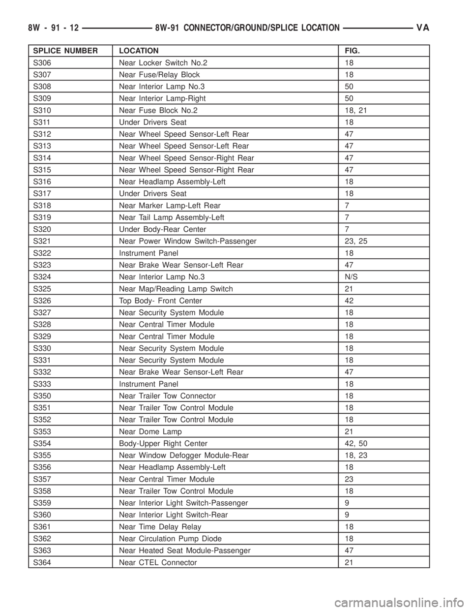
SPLICE NUMBER LOCATION FIG.
S306 Near Locker Switch No.2 18
S307 Near Fuse/Relay Block 18
S308 Near Interior Lamp No.3 50
S309 Near Interior Lamp-Right 50
S310 Near Fuse Block No.2 18, 21
S311 Under Drivers Seat 18
S312 Near Wheel Speed Sensor-Left Rear 47
S313 Near Wheel Speed Sensor-Left Rear 47
S314 Near Wheel Speed Sensor-Right Rear 47
S315 Near Wheel Speed Sensor-Right Rear 47
S316 Near Headlamp Assembly-Left 18
S317 Under Drivers Seat 18
S318 Near Marker Lamp-Left Rear 7
S319 Near Tail Lamp Assembly-Left 7
S320 Under Body-Rear Center 7
S321 Near Power Window Switch-Passenger 23, 25
S322 Instrument Panel 18
S323 Near Brake Wear Sensor-Left Rear 47
S324 Near Interior Lamp No.3 N/S
S325 Near Map/Reading Lamp Switch 21
S326 Top Body- Front Center 42
S327 Near Security System Module 18
S328 Near Central Timer Module 18
S329 Near Central Timer Module 18
S330 Near Security System Module 18
S331 Near Security System Module 18
S332 Near Brake Wear Sensor-Left Rear 47
S333 Instrument Panel 18
S350 Near Trailer Tow Connector 18
S351 Near Trailer Tow Control Module 18
S352 Near Trailer Tow Control Module 18
S353 Near Dome Lamp 21
S354 Body-Upper Right Center 42, 50
S355 Near Window Defogger Module-Rear 18, 23
S356 Near Headlamp Assembly-Left 18
S357 Near Central Timer Module 23
S358 Near Trailer Tow Control Module 18
S359 Near Interior Light Switch-Passenger 9
S360 Near Interior Light Switch-Rear 9
S361 Near Time Delay Relay 18
S362 Near Circulation Pump Diode 18
S363 Near Heated Seat Module-Passenger 47
S364 Near CTEL Connector 21
8W - 91 - 12 8W-91 CONNECTOR/GROUND/SPLICE LOCATIONVA
Page 1572 of 2305
OPERATION
All of the circuits entering and leaving the fuse
block do so through the instrument panel wire har-
ness. Internal connection of all of the fuse block cir-
cuits is accomplished by an intricate combination of
hard wiring and bus bars. Internal relays and micro
processors allow the vehicle electronics to control
some of the power distribution circuits throughout
the vehicle. Refer to the Wiring section for complete
circuit diagrams.
REMOVAL
(1) Disconnect and isolate the negative battery
cable.
(2) Remove fuse block cover by rotating locking
screw 90É.
(3) Remove the steering column cover. Refer to the
Body section for the procedure.
(4) Unscrew fuse block connections and disconnect
all electrical connectors from the fuse block.
(5) Remove the fuse block from the steering col-
umn.
INSTALLATION
(1) Position the fuse block in the steering column.
(2) Install fuse block connections and connect all
electrical connectors on the fuse block.
(3) Install the steering column cover. Refer to the
Body section for the procedure.
(4) Install fuse block cover by rotating locking
screw 90É.
(5) Connect the negative battery cable.
(6) Set time and radio stations.
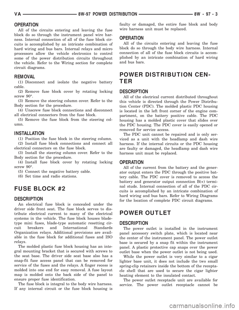
FUSE BLOCK #2
DESCRIPTION
An electrical fuse block is concealed under the
driver side front seat. The fuse block serves to dis-
tribute electrical current to many of the electrical
systems in the vehicle. The fuse block houses blade-
type mini fuses, blade-type automatic resetting cir-
cuit breakers and International Standards
Organization relays. Additional provisions are avail-
able in the fuse block for additional fuses and ISO
relays.
The molded plastic fuse block housing has an inte-
gral mounting bracket that is secured with screws to
the seat base. The driver side seat base also has a
snap-fit fuse access panel that can be removed for
service of the fuses and the relays. A finger recess is
molded into one end for easy removal. A fuse layout
map is molded onto the back side of the panel to
ensure proper fuse identification.
The fuse block is integral to the body wire harness.
If any internal circuit or the fuse block housing isfaulty or damaged, the entire fuse block and body
wire harness unit must be replaced.
OPERATION
All of the circuits entering and leaving the fuse
block do so through the body wire harness. Internal
connection of all of the fuse block circuits is accom-
plished by an intricate combination of hard wiring
and bus bars.
POWER DISTRIBUTION CEN-
TER
DESCRIPTION
All of the electrical current distributed throughout
this vehicle is directed through the Power Distribu-
tion Center (PDC). The molded plastic PDC housing
is located in the left front corner of the engine com-
partment, on the battery positive cable. The PDC
housing has a molded plastic cover that slides over
the PDC housing. The PDC cover is easily opened or
removed for service access.
The PDC unit cannot be repaired and is only ser-
viced as a unit with the headlamp and dash wire
harness. If the internal circuits or the PDC housing
are faulty or damaged, the headlamp and dash wire
harness unit must be replaced.
OPERATION
All of the current from the battery and the gener-
ator output enters the PDC through the positive bat-
tery cable. The PDC cover is removed to access the
battery and generator output connection B(+) termi-
nal studs. Internal connection of all of the PDC cir-
cuits is accomplished by an intricate combination of
hard wiring and bus bars. Refer to Wiring Diagrams
for the location of complete PDC circuit diagrams.
POWER OUTLET
DESCRIPTION
The power outlet is installed in the instrument
panel accessory switch plate, which is located near
the center of the instrument panel. The power outlet
base is secured by a snap fit within the instrument
panel. A plastic protective cap snaps over the power
outlet base when the power outlet is not being used.
While the power outlet is very similar to a cigar
lighter base unit, it does not include the two small
spring-clip retainers inside the bottom of the recepta-
cle shell that are used to secure the cigar lighter
heating element to the insulated contact.
The power outlet receptacle unit are available for
service. The power outlet receptacle cannot be
VA8W-97 POWER DISTRIBUTION 8W - 97 - 3
Page 1662 of 2305
OPERATION
Intake air is drawn through the air cleaner and
into the turbocharger compressor housing. Pressur-
ized air from the turbocharger then flows forward
through the charge air cooler located in front of the
radiator. From the charge air cooler the air flows
back into the intake manifold.
DIAGNOSIS AND TESTING - CHARGE AIR
COOLER SYSTEM - LEAKS
NOTE: Slight engine oil pooling in the charge air
inlet hose IS NOT premature turbocharger failure.
Slight pooling is the normal result of the breather
system. Test the air breather tube for normal oper-
ation by referring to the appropriate diagnostic
manual.
Low turbocharger boost pressure and low engine
performance can be caused by leaks in the charge air
cooler or it's plumbing. The following procedure out-
lines how to check for leaks in the charge air cooler
system.
(1) Loosen clamp and remove turbocharger to air
inlet duct rubber sleeve from turbocharger.
(2) Insert Special Tool 8442 Adapter into the rub-
ber sleeve. Tighten existing clamp to 8 N´m (72
in.lbs.).
CAUTION: Do not apply more than 138 kpa (20 psi)
air pressure to the charge air cooler system, sever
damage to the charge air cooler system may occur.
(3) Connect regulated air supply to air fitting on
Special Tool 8442 Adapter. Set air pressure to a Max-
imum of 138 kpa (20 psi).
(4) Using soapy water check the air inlet ducts,
rubber sleeves, charge air cooler and intake manifold
for leaks.
REMOVAL
(1) Remove front bumper.
(2) Remove headlamp assemblies.
(3) Remove front cross member together with front
grille.
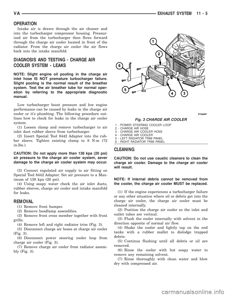
(4) Remove left and right radiator trim (Fig. 3).
(5) Disconnect charge air hoses at charge air cooler
(Fig. 3).
(6) Disconnect power steering cooler loop from
charge air cooler (Fig. 3).
(7) Remove charge air cooler from radiator assem-
bly (Fig. 3).
CLEANING
CAUTION: Do not use caustic cleaners to clean the
charge air cooler. Damage to the charge air cooler
will result.
NOTE: If internal debris cannot be removed from
the cooler, the charge air cooler MUST be replaced.
(1) If the engine experiences a turbocharger failure
or any other situation where oil or debris get into the
charge air cooler, the charge air cooler must be
cleaned internally.
(2) Position the charge air cooler so the inlet and
outlet tubes are vertical.
(3) Flush the cooler internally with solvent in the
direction opposite of normal air flow.
(4) Shake the cooler and lightly tap on the end
tanks with a rubber mallet to dislodge trapped
debris.
(5) Continue flushing until all debris or oil are
removed.
(6) Rinse the cooler with hot soapy water to
remove any remaining solvent.
(7) Rinse thoroughly with clean water and blow
dry with compressed air.
Fig. 3 CHARGE AIR COOLER
1 - POWER STEERING COOLER LOOP
2 - CHARGE AIR HOSE
3 - CHARGE AIR COOLER HOSE
4 - CHARGE AIR COOLER
5 - LEFT RADIATOR TRIM PANEL
6 - RIGHT RADIATOR TRIM PANEL
VAEXHAUST SYSTEM 11 - 5
Page 1663 of 2305
INSPECTION
Visually inspect the charge air cooler for cracks,
holes, or damage. Inspect the tubes, fins, and welds
for tears, breaks, or other damage. Replace the
charge air cooler if damage is found.
Pressure test the charge air cooler, using Charge
Air Cooler Tester Kit.
INSTALLATION
(1) Install charge air cooler to radiator (Fig. 3).
(2) Connect power steering cooler loop to charge
air cooler (Fig. 3).
(3) Connect charge air hoses (Fig. 3).
(4) Install both radiator trim pieces (Fig. 3).
(5) Install front grille with front cross member.
(6) Install headlamp assemblies.
(7) Install front bumper.
TURBOCHARGER
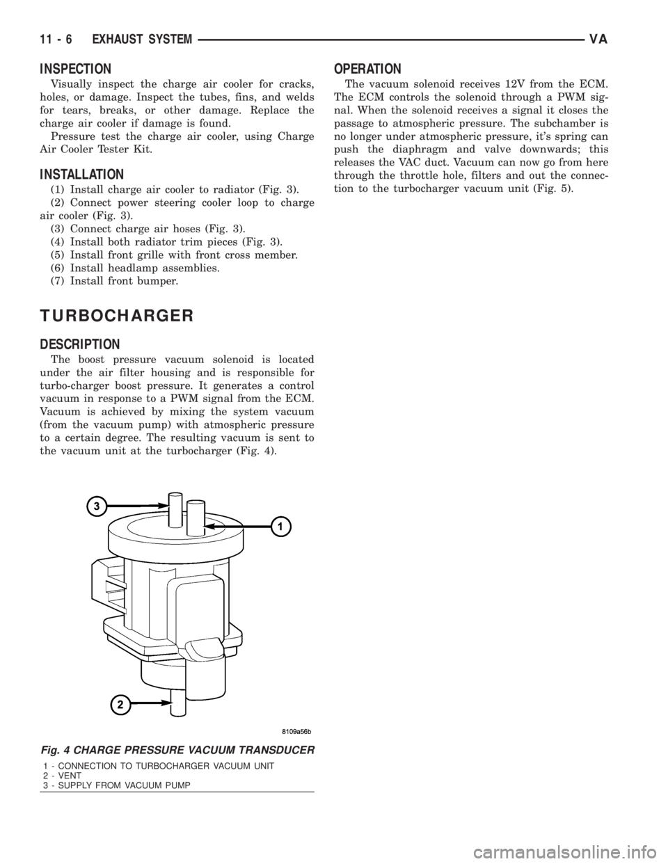
DESCRIPTION
The boost pressure vacuum solenoid is located
under the air filter housing and is responsible for
turbo-charger boost pressure. It generates a control
vacuum in response to a PWM signal from the ECM.
Vacuum is achieved by mixing the system vacuum
(from the vacuum pump) with atmospheric pressure
to a certain degree. The resulting vacuum is sent to
the vacuum unit at the turbocharger (Fig. 4).
OPERATION
The vacuum solenoid receives 12V from the ECM.
The ECM controls the solenoid through a PWM sig-
nal. When the solenoid receives a signal it closes the
passage to atmospheric pressure. The subchamber is
no longer under atmospheric pressure, it's spring can
push the diaphragm and valve downwards; this
releases the VAC duct. Vacuum can now go from here
through the throttle hole, filters and out the connec-
tion to the turbocharger vacuum unit (Fig. 5).
Fig. 4 CHARGE PRESSURE VACUUM TRANSDUCER
1 - CONNECTION TO TURBOCHARGER VACUUM UNIT
2 - VENT
3 - SUPPLY FROM VACUUM PUMP
11 - 6 EXHAUST SYSTEMVA
Page 1992 of 2305
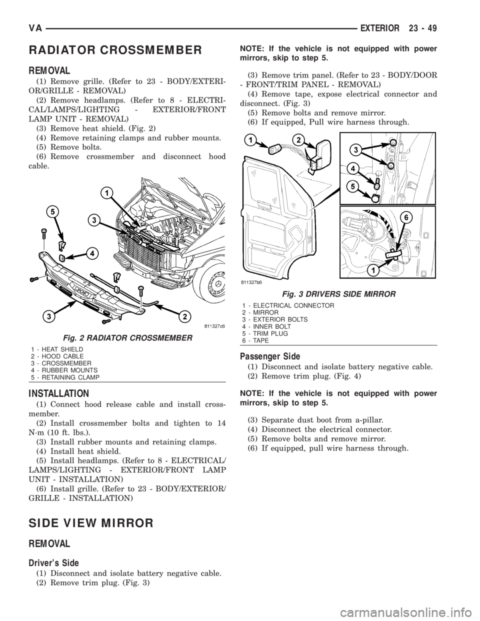
RADIATOR CROSSMEMBER
REMOVAL
(1) Remove grille. (Refer to 23 - BODY/EXTERI-
OR/GRILLE - REMOVAL)
(2) Remove headlamps. (Refer to 8 - ELECTRI-
CAL/LAMPS/LIGHTING - EXTERIOR/FRONT
LAMP UNIT - REMOVAL)
(3) Remove heat shield. (Fig. 2)
(4) Remove retaining clamps and rubber mounts.
(5) Remove bolts.
(6) Remove crossmember and disconnect hood
cable.
INSTALLATION
(1) Connect hood release cable and install cross-
member.
(2) Install crossmember bolts and tighten to 14
N´m (10 ft. lbs.).
(3) Install rubber mounts and retaining clamps.
(4) Install heat shield.
(5) Install headlamps. (Refer to 8 - ELECTRICAL/
LAMPS/LIGHTING - EXTERIOR/FRONT LAMP
UNIT - INSTALLATION)
(6) Install grille. (Refer to 23 - BODY/EXTERIOR/
GRILLE - INSTALLATION)
SIDE VIEW MIRROR
REMOVAL
Driver's Side
(1) Disconnect and isolate battery negative cable.
(2) Remove trim plug. (Fig. 3)NOTE: If the vehicle is not equipped with power
mirrors, skip to step 5.
(3) Remove trim panel. (Refer to 23 - BODY/DOOR
- FRONT/TRIM PANEL - REMOVAL)
(4) Remove tape, expose electrical connector and
disconnect. (Fig. 3)
(5) Remove bolts and remove mirror.
(6) If equipped, Pull wire harness through.
Passenger Side
(1) Disconnect and isolate battery negative cable.
(2) Remove trim plug. (Fig. 4)
NOTE: If the vehicle is not equipped with power
mirrors, skip to step 5.
(3) Separate dust boot from a-pillar.
(4) Disconnect the electrical connector.
(5) Remove bolts and remove mirror.
(6) If equipped, pull wire harness through.
Fig. 2 RADIATOR CROSSMEMBER
1 - HEAT SHIELD
2 - HOOD CABLE
3 - CROSSMEMBER
4 - RUBBER MOUNTS
5 - RETAINING CLAMP
Fig. 3 DRIVERS SIDE MIRROR
1 - ELECTRICAL CONNECTOR
2 - MIRROR
3 - EXTERIOR BOLTS
4 - INNER BOLT
5 - TRIM PLUG
6 - TAPE
VAEXTERIOR 23 - 49
Page 2107 of 2305
there are no objects placed in front of the radiator
grille openings in the front of the vehicle or foreign
material on the condenser fins that might obstruct
proper air flow. Also, any factory-installed air seals or
shrouds must be properly reinstalled following radia-
tor or condenser service.
The condenser cannot be repaired and, if faulty or
damaged, it must be replaced.
REMOVAL
WARNING: Refer to the applicable warnings and
cautions for this system before performing the fol-
lowing operation (Refer to 24 - HEATING & AIR
CONDITIONING/PLUMBING - WARNINGS) and (Refer
to 24 - HEATING & AIR CONDITIONING/PLUMBING -
CAUTIONS). Failure to follow the warnings and cau-
tions could result in possible personal injury or
death.
(1) Disconnect and isolate the negative battery
cable.
(2) Recover the refrigerant from the refrigerant
system (Refer to 24 - HEATING & AIR CONDITION-
ING/PLUMBING - STANDARD PROCEDURE -
REFRIGERANT SYSTEM RECOVERY).
(3) Remove the front fascia.
(4) Remove the grille (Refer to 23 - BODY/EXTE-
RIOR/GRILLE - REMOVAL).
(5) Remove the headlamps from their mounts.
(6) Remove the radiator crossmember (Refer to 23
- BODY/EXTERIOR/RADIATOR CROSSMEMBER -
REMOVAL).
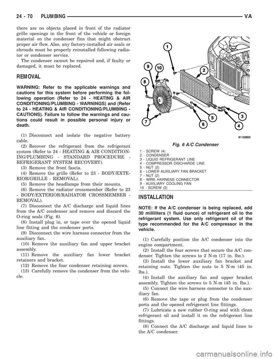
(7) Disconnect the A/C discharge and liquid lines
from the A/C condenser and remove and discard the
O-ring seals (Fig. 6).
(8) Install plug in, or tape over the opened liquid
line fitting and the condenser ports.
(9) Disconnect the wire harness connector from the
auxiliary fan.
(10) Remove the auxiliary fan and upper bracket
assembly.
(11) Remove the auxiliary fan lower bracket
retainers and bracket.
(12) Remove the four condenser retaining screws.
(13) Carefully remove the condenser from the vehi-
cle.
INSTALLATION
NOTE: If the A/C condenser is being replaced, add
30 milliliters (1 fluid ounce) of refrigerant oil to the
refrigerant system. Use only refrigerant oil of the
type recommended for the A/C compressor in the
vehicle.
(1) Carefully position the A/C condenser into the
engine compartment.
(2) Install the four screws that secure the A/C con-
denser. Tighten the screws to 2 N´m (17 in. lbs.).
(3) Install the lower auxiliary fan bracket and
retaining nuts. Tighten the nuts to 5 N´m (45 in.
lbs.).
(4) Install the auxiliary fan and upper bracket
assembly. Tighten the screws to 5 N´m (45 in. lbs.).
(5) Connect the wire harness connector to the aux-
iliary fan.
(6) Remove the tape or plug from the condenser
ports and the opened refrigerant line fittings.
(7) Lubricate a new rubber O-ring seal with clean
refrigerant oil and install it on the refrigerant line
fittings.
(8) Connect the A/C discharge and liquid lines to
the A/C condenser.
Fig. 6 A/C Condenser
1 - SCREW (4)
2 - CONDENSER
3 - LIQUID REFRIGERANT LINE
4 - COMPRESSOR DISCHARGE LINE
5 - NUT (2)
6 - LOWER AUXILIARY FAN BRACKET
7 - NUT (2)
8 - WIRE HARNESS CONNECTOR
9 - AUXILIARY COOLING FAN
10 - SCREW (2)
24 - 70 PLUMBINGVA
Page 2108 of 2305
(9) Install the nuts that secure the A/C discharge
and liquid lines to the A/C condenser. Tighten the
nuts to 33 N´m (24 ft. lbs.).
(10) Install the radiator crossmember (Refer to 23
- BODY/EXTERIOR/RADIATOR CROSSMEMBER -
INSTALLATION).
(11) Install the headlamps into their mounts.
(12) Install the grille (Refer to 23 - BODY/EXTE-
RIOR/GRILLE - INSTALLATION).
(13) Install the front fascia.
(14) Reconnect the negative battery cable.
(15) Evacuate the refrigerant system (Refer to 24 -
HEATING & AIR CONDITIONING/PLUMBING -
STANDARD PROCEDURE - REFRIGERANT SYS-
TEM EVACUATE).
(16) Recharge the refrigerant system (Refer to 24 -
HEATING & AIR CONDITIONING/PLUMBING -
STANDARD PROCEDURE - REFRIGERANT SYS-
TEM CHARGE).
A / C DISCHARGE LINE
REMOVAL
WARNING: Refer to the applicable warnings and
cautions for this system before performing the fol-
lowing operation (Refer to 24 - HEATING & AIR
CONDITIONING/PLUMBING - WARNINGS) and (Refer
to 24 - HEATING & AIR CONDITIONING/PLUMBING -
CAUTIONS). Failure to follow the warnings and cau-
tions could result in possible personal injury or
death.
(1) Disconnect and isolate the negative battery
cable.
(2) Recover the refrigerant from the refrigerant
system (Refer to 24 - HEATING & AIR CONDITION-
ING/PLUMBING - STANDARD PROCEDURE -
REFRIGERANT RECOVERY).
(3) Remove the grille (Refer to 23 - BODY/EXTE-
RIOR/GRILLE - REMOVAL).
(4) Remove the nut that secures the discharge line
fitting to the condenser on the left side of the con-
denser.
(5) Disconnect the discharge line fitting from the
condenser inlet port.
(6) Remove the seal from the discharge line fitting
and discard.
(7) Install plug in, or tape over the opened dis-
charge line fitting and the condenser inlet port.
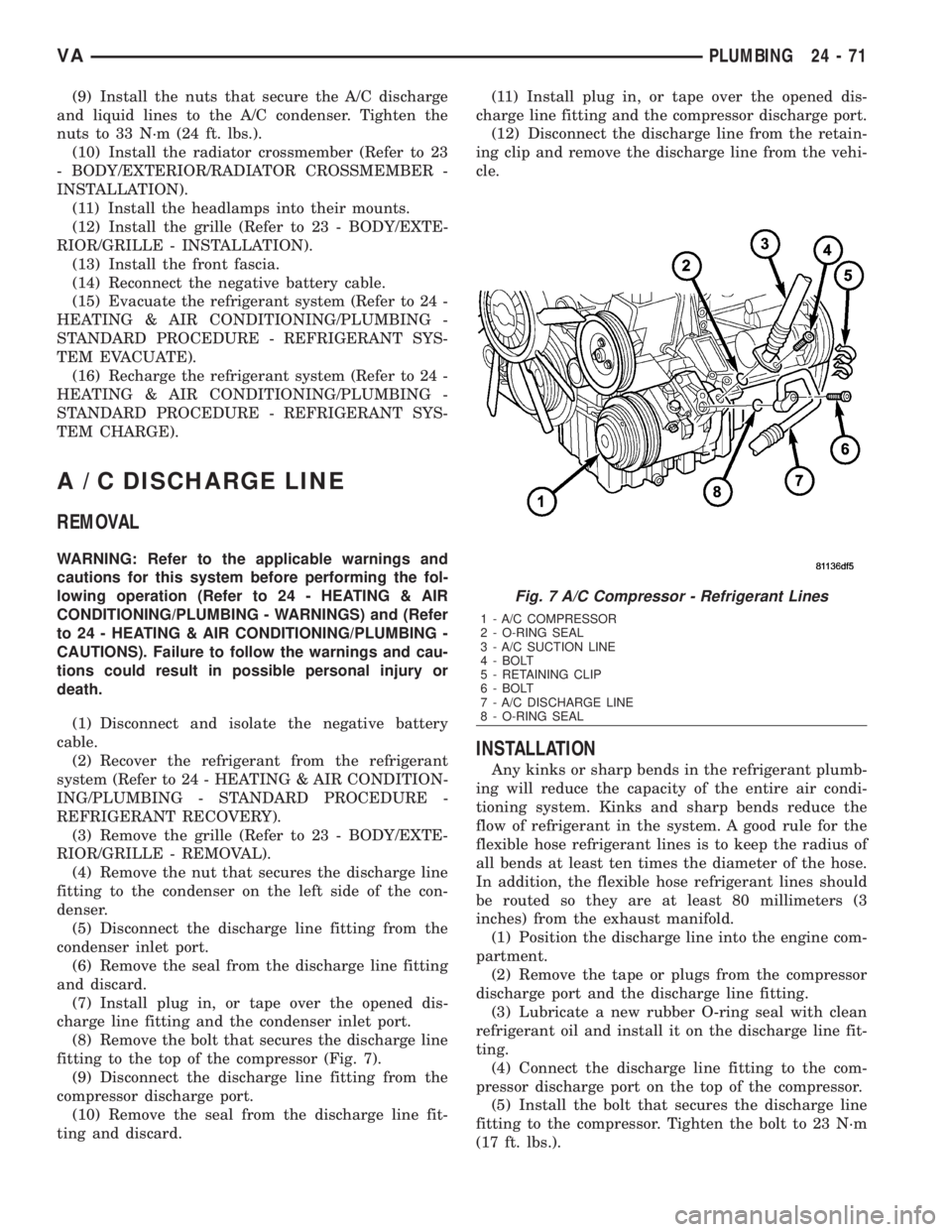
(8) Remove the bolt that secures the discharge line
fitting to the top of the compressor (Fig. 7).
(9) Disconnect the discharge line fitting from the
compressor discharge port.
(10) Remove the seal from the discharge line fit-
ting and discard.(11) Install plug in, or tape over the opened dis-
charge line fitting and the compressor discharge port.
(12) Disconnect the discharge line from the retain-
ing clip and remove the discharge line from the vehi-
cle.
INSTALLATION
Any kinks or sharp bends in the refrigerant plumb-
ing will reduce the capacity of the entire air condi-
tioning system. Kinks and sharp bends reduce the
flow of refrigerant in the system. A good rule for the
flexible hose refrigerant lines is to keep the radius of
all bends at least ten times the diameter of the hose.
In addition, the flexible hose refrigerant lines should
be routed so they are at least 80 millimeters (3
inches) from the exhaust manifold.
(1) Position the discharge line into the engine com-
partment.
(2) Remove the tape or plugs from the compressor
discharge port and the discharge line fitting.
(3) Lubricate a new rubber O-ring seal with clean
refrigerant oil and install it on the discharge line fit-
ting.
(4) Connect the discharge line fitting to the com-
pressor discharge port on the top of the compressor.
(5) Install the bolt that secures the discharge line
fitting to the compressor. Tighten the bolt to 23 N´m
(17 ft. lbs.).
Fig. 7 A/C Compressor - Refrigerant Lines
1 - A/C COMPRESSOR
2 - O-RING SEAL
3 - A/C SUCTION LINE
4 - BOLT
5 - RETAINING CLIP
6 - BOLT
7 - A/C DISCHARGE LINE
8 - O-RING SEAL
VAPLUMBING 24 - 71
Page 2158 of 2305
INDEX
ABS INDICATOR.......................8J-9ACCELERATOR PEDAL POSITION SENSOR. . . 14-32
ACCESSORY SWITCH BEZEL............23-56
ADR INDICATOR.....................8J-10
AIR CLEANER ELEMENT................9-21
AIR CLEANER HOUSING................9-21
AIR FILTER ....................24-45, 24-58
AIR OUTLET TEMPERATURE SENSOR....24-16
AIR OUTLETS.......................24-45
AIRBAG CONTROL MODULE.............8O-8
AIRBAG INDICATOR...................8J-11
ALB CONTROLLER....................5-16
ALB LEVER..........................5-16
AMBIENT TEMPERATURE INDICATOR.....8J-11
AMBIENT TEMPERATURE SENSOR.......24-17
ANTENNA BODY & CABLE..............8A-1
ARMREST..........................23-79
ASH RECEIVER......................23-57
ASH RECEIVER / CIGAR LIGHTER LAMP
UNIT..............................8L-30
ASSIST HANDLE.....................23-71
AUDIO..............................8A-1
AUTOMATIC TRANSMISSION NAG1 -
SERVICE INFORMATION................21-3
A - PILLAR TRIM.....................23-70
A / C CLUTCH RELAY.................24-24
A / C COMPRESSOR CLUTCH COIL.......24-12
A / C COMPRESSOR CLUTCH............24-8
A / C COMPRESSOR..................24-66
A / C CONDENSER COVER.............24-52
A / C CONDENSER FAN RELAY..........24-26
A / C CONDENSER HOUSING...........24-52
A / C CONDENSER....................24-69
A / C CONTROL MODULE..............24-28
A / C DISCHARGE LINE................24-71
A / C EVAPORATOR COVER.............24-55
A / C EVAPORATOR HOUSING...........24-55
A / C EVAPORATOR...................24-72
A / C EXPANSION VALVE...............24-73
A / C HEATER CONTROL...............24-12
A / C HIGH PRESSURE SWITCH.........24-30
A / C LOW PRESSURE SWITCH.........24-32
A / C PRESSURE TRANSDUCER.........24-14
BACKLITE - BULKHEAD TRIM PANEL.....23-84
BACKUP LAMP BULB..................8L-5
BASECOAT / CLEARCOAT FINISH........23-77
BATTERY CABLES....................8F-14
BATTERY HOLDDOWN.................8F-13
BATTERY SYSTEM.....................8F-1
BATTERY TRAY......................8F-16
BATTERY............................8F-6
BEARINGS - DIFFERENTIAL CASE.........3-38
BEARING / SEAL - AXLE HUB............3-28
BEARING / SEAL - AXLE................3-24
BELT TENSIONERS.....................7-5
BLOWER MOTOR RELAY...............24-33
BLOWER MOTOR RESISTOR............24-17
BLOWER MOTOR SWITCH........24-19, 24-35
BLOWER MOTOR...............24-47, 24-58
BODY...............................23-1
BOOST PRESSURE SENSOR............14-33
BRAKE INDICATOR...................8J-12
BRAKE LAMP SWITCH.................8L-6
BRAKE LINES.........................5-8
BRAKE PADS / SHOES...................5-8
BRAKE WEAR INDICATOR..............8J-13
BRAKES - ABS........................5-30
BRAKES - BASE........................5-2
BRAKE / PARK LAMP BULB.............8L-7
BULKHEAD TRIM PANEL...............23-72
BUMPERS...........................13-1
BUSHINGS............................2-3
B - PILLAR TRIM.....................23-71
CABIN HEATER.....................24-104
CABLE TENSIONER....................5-24
CABLE..............................8P-2
CABLES.............................5-24
CAMSHAFT POSITION SENSOR..........14-33
CAMSHAFT(S)........................9-28
CARGO LAMP SWITCH................8L-31
CARGO / DOME LAMP BULB............8L-30
CARGO / DOME LAMP UNIT............8L-31
CARPETS AND FLOOR MATS...........23-72
CATALYTIC CONVERTER
................11-3
CENTER BEARING
......................3-9
CENTER HIGH MOUNTED STOP LAMP BULB. . . 8L-8CENTER HIGH MOUNTED STOP LAMP UN.....8L-8
CENTER ROLLER ARM
................23-36CENTER TRACK......................23-37
CENTRAL TIMER MODULE..............8E-1
CHARGE AIR COOLER AND PLUMBING....11-4
CHARGING INDICATOR................8J-14
CHARGING SYSTEM..................8F-17
CHECK VALVE.......................8R-11
CHECK.......................23-13, 23-23
CHIME / BUZZER......................8B-1
CIGAR LIGHTER OUTLET............8W-97-1
CIRCUIT BREAKER.................8W-97-2
CLEARANCE LAMP BULB...............8L-9
CLEARANCE LAMP UNIT................8L-9
CLOCK.............................8J-14
CLOCKSPRING......................8O-12
CLUSTER BEZEL.....................23-55
COLUMN............................19-4
CONNECTOR.......................Intro.-9
CONNECTOR/GROUND/SPLICE
LOCATION........................8W-91-1
CONTROLLER ANTILOCK BRAKE.........8E-3
COOLANT LEVEL SENSOR...............7-13
COOLANT LOW INDICATOR.............8J-15
COOLANT............................7-9
COOLING.............................7-1
COWL TRIM........................23-73
CRANKCASE VENTILATION BREATHER......25-2
CRANKCASE VENTILATION HEATER.......25-1
CRANKSHAFT OIL SEAL - FRONT.........9-42
CRANKSHAFT OIL SEAL - REAR..........9-41
CRANKSHAFT POSITION SENSOR........14-35
CRANKSHAFT........................9-39
CUP HOLDER........................23-57
CYLINDER HEAD COVER(S).............9-33
CYLINDER HEAD......................9-22
DAYTIME RUNNING LAMP RELAY.......8L-10
DEFROSTER DUCTS..................24-47
DIFFERENTIAL........................3-31
DIODE............................Intro.-9
DISC BRAKE CALIPER ADAPTER.........5-14
DISC BRAKE CALIPERS.................5-11
DOME LAMP / INTRUSION SENSOR
BULB..............................8L-33
DOME LAMP / INTRUSION SENSOR......8L-33
DOME / READING LAMP BULB..........8L-32
DOME / READING LAMP UNIT..........8L-32
DOOR GLASS............23-15, 23-30, 23-46
DOOR JAMB SWITCH.................8L-34
DOOR LOCK MOTOR...................8N-1
DOOR OPENING SEALS................23-90
DOOR........................23-14, 23-23
DRIVE BELTS..........................7-5
DRIVER AIRBAG.....................8O-16
DRIVER HEATED SEAT SWITCH.........8G-11
D - PILLAR TRIM.....................23-73
ELECTRIC COOLANT PUMP.............24-75
ELECTRICAL.........................5-30
ELECTROHYDRAULIC UNIT............21-105
ENGINE BLOCK HEATER................7-14
ENGINE BLOCK.......................9-37
ENGINE CONTROL MODULE.............8E-3
ENGINE COOLANT TEMP SENSOR........7-15
ENGINE COOLANT THERMOSTAT.........7-16
ENGINE CRADLE CROSSMEMBER........13-8
ENGINE TEMPERATURE GAUGE.........8J-15
ENGINE..............................9-2
ENTRY / EXIT LAMP BULB.............8L-34
ENTRY / EXIT LAMP UNIT..............8L-35
ESP INDICATOR......................8J-16
EVAPORATOR TEMPERATURE
SENSOR......................24-19, 24-37
EXHAUST GAS RECIRCULATION..........25-4
EXHAUST MANIFOLD..................9-68
EXHAUST PIPE.......................11-3
EXHAUST SYSTEM....................11-1
EXHAUST TUBE.....................24-105
EXTERIOR HANDLE.......23-16, 23-31, 23-35
FAN DRIVE VISCOUS CLUTCH...........7-17
FASTENER IDENTIFICATION...........Intro.-3
FASTENER USAGE...................Intro.-6
FINESSE SANDING / BUFFING & POLISH . . 23-78
FLOOR DISTRIBUTION DUCTS..........24-47
FLUID AND FILTER..................21-131
FLUID CAPACITIES.....................0-5
FLUID COOLER TUBE
.................19-13
FLUID FILL / CHECK LOCATIONS
..........0-5
FLUID RESERVOIR
....................5-15
FLUID TYPES
..........................0-1
FLYWHEEL
...........................9-43FOG LAMP BULB.....................8L-10
FOG LAMP RELAY....................8L-11
FOG LAMP SWITCH...................8L-12
FRAME..............................13-3
FREEWHEELING CLUTCH.............21-135
FRONT BUMPER - STEPS...............13-2
FRONT DOOR INNER BELT
WEATHERSTRIP.....................23-90
FRONT DOOR OUTER BELT
WEATHERSTRIP.....................23-90
FRONT FASCIA.......................13-2
FRONT LAMP UNIT...................8L-13
FRONT POSITION LAMP BULB..........8L-14
FRONT SEAT BELT & RETRACTOR.......8O-20
FRONT SEAT BELT BUCKLE............8O-23
FRONT TURN / PARK / SIDE MARKER
LAMP BULB.........................8L-15
FRONT WHEEL SPEED SENSOR..........5-31
FRONT...............................2-1
FUEL DELIVERY.......................14-6
FUEL DOSING PUMP.................24-106
FUEL DRAIN TUBES..................14-10
FUEL FILL DOOR.....................23-48
FUEL FILTER CLOGGED INDICATOR......8J-17
FUEL FILTER........................14-10
FUEL GAUGE........................8J-17
FUEL INJECTOR.......................14-35
FUEL LEVEL SENDING UNIT / SENSOR....14-28
FUEL LINE.........................24-107
FUEL LINES.........................14-11
FUEL PRESSURE SENSOR.............14-39
FUEL PRESSURE SOLENOID............14-40
FUEL PUMP MODULE.................14-18
FUEL PUMP.........................14-13
FUEL QUANTITY CONTROL VALVE.......14-21
FUEL RAIL PRESSURE SENSOR.........14-12
FUEL RAIL..........................14-22
FUEL SYSTEM........................14-1
FUEL TANK.........................14-23
FUEL TEMPERATURE SENSOR..........14-42
FUSE BLOCK #1...................8W-97-2
FUSE BLOCK #2...................8W-97-3
GAP AND FLUSH.....................23-91
GEAR SELECTOR INDICATOR...........8J-18
GEAR...............................19-7
GEARSHIFT CABLE..................21-138
GEAR - PINION / RING.................3-41
GENERATOR DECOUPLER PULLEY.......8F-19
GENERATOR........................8F-18
GLOVE BOX.........................23-58
GLOW PLUG RELAY....................8I-1
GLOW PLUG..........................8I-1
GRILLE............................23-48
HCU (HYDRAULIC CONTROL UNIT).......5-36
HEADLAMP LEVELING MOTOR..........8L-16
HEADLAMP LEVELING SWITCH.........8L-17
HEADLINER.........................23-73
HEADREST..........................23-79
HEATED GLASS.......................8G-1
HEATED MIRRORS....................8G-9
HEATED SEAT ELEMENT...............8G-12
HEATED SEAT RELAY.................8G-12
HEATED SEAT SENSOR................8G-13
HEATED SEATS ......................8G-10
HEATER CORE.......................24-76
HEATER UNIT......................24-110
HEATING & AIR CONDITIONING..........24-1
HIGH BEAM HEADLAMP BULB..........8L-18
HIGH BEAM INDICATOR...............8J-19
HINGE..................23-17, 23-32, 23-51
HOISTING............................0-5
HOLDING CLUTCH B1................21-143
HOLDING CLUTCH B2................21-148
HOLDING CLUTCHES.................21-141
HOOD.............................23-51
HORN SWITCH.......................8H-1
HORN..............................8H-1
HOSES.............................19-14
HUB / BEARING........................2-4
HVAC HOUSING......................24-48
HYDRAULIC / MECHANICAL..............5-5
IGNITION CONTROL....................8I-1
INLET HOSE........................24-111
INPUT CLUTCH K1
...................21-92
INPUT CLUTCH K2
...................21-97
INPUT CLUTCH K3
..................21-102
INPUT CLUTCHES
....................21-90
INPUT SPEED SENSORS
..............21-153
VAINDEX 1
Description Group-Page Description Group-Page Description Group-Page