Page 366 of 2305
TEST ACTION APPLICABILITY
7 Turn the ignition off.
Visually inspect the related wiring harness.
Look for any chafed, pierced, pinched, or partially broken wires.
Look for broken, bent, pushed out, or corroded terminals.
Were any problems found?All
Ye s!Repair as necessary.
Perform ABS VERIFICATION TEST - VER 1.
No!Test Complete.
45
BRAKES (CAB)
LEFT FRONT WHEEL SPEED SENSOR CIRCUIT ÐContinued
Page 367 of 2305

Symptom List:
LEFT FRONT WHEEL SPEED SENSOR SIGNAL
LEFT REAR WHEEL SPEED SENSOR SIGNAL
RIGHT FRONT WHEEL SPEED SENSOR SIGNAL
RIGHT REAR WHEEL SPEED SENSOR SIGNAL
WHEEL SPEED SENSOR SIGNAL ERROR
Test Note: All symptoms listed above are diagnosed using the same tests.
The title for the tests will be LEFT FRONT WHEEL SPEED
SENSOR SIGNAL.
When Monitored and Set Condition:
LEFT FRONT WHEEL SPEED SENSOR SIGNAL
When Monitored: Ignition On - Continuously
Set Condition: When the value of the wheel speed sensor signal is missing at vehicle
speeds over 40 km/h (25 mph) OR during a start-up test with vehicle speeds over 12km/h
(8 mph) OR the vehicle is accelerated by 18 km/h (12 mph) after a wheel speed sensor
signal has been lost.
POSSIBLE CAUSES
INTERMITTENT WHEEL SPEED SENSOR SIGNAL DTC
DAMAGED SENSOR/CAB HARNESS CONNECTOR
DAMAGED WHEEL SPEED SENSOR TONE WHEEL
EXCESSIVE WHEEL SPEED SENSOR AIR GAP
DAMAGED WHEEL BEARING
DAMAGED BRAKE LININGS/COMPONENTS
WHEEL SPEED SENSOR FAILURE
ANTI-LOCK BRAKE CONTROLLER
TEST ACTION APPLICABILITY
1NOTE: Refer to the symptom list and repair any WHEEL SPEED SENSOR
CIRCUIT DTCs before continuing.
Turn the ignition on.
With the DRBIIItin Sensors, monitor ALL the Wheel Speed Sensor signals while an
assistant drives the vehicle.
Slowly accelerate from a stop to 65 km/h (40 mph).
NOTE: Wheel Speed should not vary by more than 10% from wheel to wheel
when driving in a straight line.
Do any of the Wheel Speed Sensor signals vary by greater than 10% while driving in
a straight line?All
Ye s!Go To 2
No!Go To 8
46
BRAKES (CAB)
Page 368 of 2305

TEST ACTION APPLICABILITY
2 Turn the ignition off.
Inspect the CAB harness connector and affected Wheel Speed Sensor.
Inspect for looseness.
Inspect wiring harness.
Inspect for metal chips on sensor.
Is the Wheel Speed Sensor or CAB harness connector damaged?All
Ye s!Repair as necessary.
Perform ABS VERIFICATION TEST - VER 1.
No!Go To 3
3 Turn the ignition off.
Inspect the affected Wheel Speed Sensor(s) tone wheel for damage, looseness, or
missing.
NOTE: Refer to the appropriate Service information, if necessary, for
procedures or specifications.
Is the affected tone wheel OK?All
Ye s!Go To 4
No!Replace the tone wheel in accordance with the Service Informa-
tion.
Perform ABS VERIFICATION TEST - VER 1.
4 Turn the ignition off.
Inspect the affected Wheel Speed Sensor air gap.
NOTE: Refer to the appropriate Service information, if necessary, for
procedures or specifications.
Is the affected air gap OK?All
Ye s!Go To 5
No!Repair as necessary.
Perform ABS VERIFICATION TEST - VER 1.
5 Turn the ignition off.
Inspect the affected Wheel Speed Sensor(s) wheel bearing.
NOTE: Refer to the appropriate Service information, if necessary, for
procedures or specifications.
Is the affected wheel bearing clearance OK?All
Ye s!Go To 6
No!Repair as necessary.
Perform ABS VERIFICATION TEST - VER 1.
6 Turn the ignition off.
Visually inspect the brakes for locking up due to lining contamination or overheating.
Inspect all brake components for defects which would cause a speed difference.
Were any problems found?All
Ye s!Repair as necessary.
Perform ABS VERIFICATION TEST - VER 1.
No!Go To 7
47
BRAKES (CAB)
LEFT FRONT WHEEL SPEED SENSOR SIGNAL ÐContinued
Page 369 of 2305

TEST ACTION APPLICABILITY
7 Turn the ignition off.
Disconnect the Anti-Lock Brake module harness connector.
Connect a voltmeter to the Wheel Speed Sensor (+) and (-) circuits at the Antilock
Brake module harness connector.
Rotate the wheel at a speed of at least one revolution per second while monitoring the
voltage.
Is the AC voltage fluctuating above 120 mV?All
Ye s!Replace the Controller Antilock Brake in accordance with the
Service Information.
Perform ABS VERIFICATION TEST - VER 1.
No!Replace the affected Wheel Speed Sensor in accordance with the
Service Information.
Perform ABS VERIFICATION TEST - VER 1.
8 Turn the ignition off.
Visually inspect the related wiring harness.
Look for any chafed, pierced, pinched, or partially broken wires.
Look for broken, bent, pushed out, or corroded terminals.
Look for any wiring conditions that may cause electromagnetic interference with the
Wheel Speed Sensor circuits.
Inspect Wheel Speed sensors, Tone Wheels, Brake Rotors, Wheel Bearings, etc, for
conditions that may cause speed variations from wheel to wheel.
Were any problems found?All
Ye s!Repair as necessary.
Perform ABS VERIFICATION TEST - VER 1.
No!Test Complete.
48
BRAKES (CAB)
LEFT FRONT WHEEL SPEED SENSOR SIGNAL ÐContinued
Page 370 of 2305
Symptom:
NO COMMUNICATION WITH BUS
When Monitored and Set Condition:
NO COMMUNICATION WITH BUS
When Monitored: Ignition On - Continuously
Set Condition: When the CAB fails to receive all module messages.
POSSIBLE CAUSES
CAN CIRCUITS SHORTED TO VOLTAGE
MODULE SHORT TO VOLTAGE
CAN CIRCUITS SHORTED TO GROUND
MODULE SHORT TO GROUND
CAN CIRCUITS SHORTED TOGETHER
ENGINE CONTROL MODULE
SENTRY KEY REMOTE ENTRY MODULE
TEST ACTION APPLICABILITY
1 Turn the ignition off.
Disconnect the Instrument Cluster harness connectors.
Turn the ignition on.
Measure the voltage between CAN C Bus (+) circuit and ground.
Measure the voltage between CAN C Bus (-) circuit and ground.
Is the voltage above 3.0 volts on either circuit?All
Ye s!Go To 2
No!Go To 3
49
BRAKES (CAB)
Page 371 of 2305

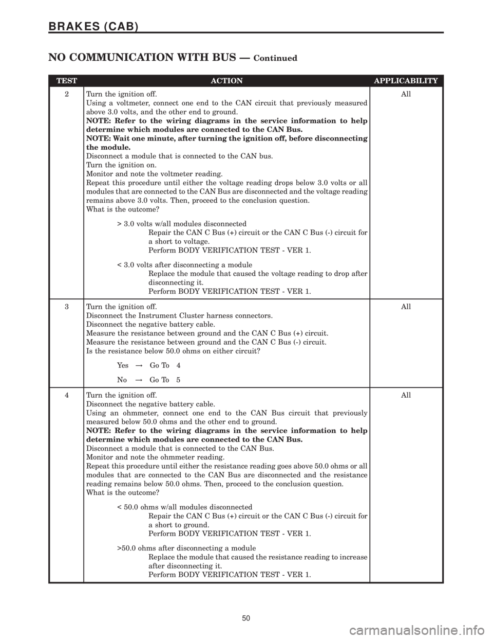
TEST ACTION APPLICABILITY
2 Turn the ignition off.
Using a voltmeter, connect one end to the CAN circuit that previously measured
above 3.0 volts, and the other end to ground.
NOTE: Refer to the wiring diagrams in the service information to help
determine which modules are connected to the CAN Bus.
NOTE: Wait one minute, after turning the ignition off, before disconnecting
the module.
Disconnect a module that is connected to the CAN bus.
Turn the ignition on.
Monitor and note the voltmeter reading.
Repeat this procedure until either the voltage reading drops below 3.0 volts or all
modules that are connected to the CAN Bus are disconnected and the voltage reading
remains above 3.0 volts. Then, proceed to the conclusion question.
What is the outcome?All
> 3.0 volts w/all modules disconnected
Repair the CAN C Bus (+) circuit or the CAN C Bus (-) circuit for
a short to voltage.
Perform BODY VERIFICATION TEST - VER 1.
< 3.0 volts after disconnecting a module
Replace the module that caused the voltage reading to drop after
disconnecting it.
Perform BODY VERIFICATION TEST - VER 1.
3 Turn the ignition off.
Disconnect the Instrument Cluster harness connectors.
Disconnect the negative battery cable.
Measure the resistance between ground and the CAN C Bus (+) circuit.
Measure the resistance between ground and the CAN C Bus (-) circuit.
Is the resistance below 50.0 ohms on either circuit?All
Ye s!Go To 4
No!Go To 5
4 Turn the ignition off.
Disconnect the negative battery cable.
Using an ohmmeter, connect one end to the CAN Bus circuit that previously
measured below 50.0 ohms and the other end to ground.
NOTE: Refer to the wiring diagrams in the service information to help
determine which modules are connected to the CAN Bus.
Disconnect a module that is connected to the CAN Bus.
Monitor and note the ohmmeter reading.
Repeat this procedure until either the resistance reading goes above 50.0 ohms or all
modules that are connected to the CAN Bus are disconnected and the resistance
reading remains below 50.0 ohms. Then, proceed to the conclusion question.
What is the outcome?All
< 50.0 ohms w/all modules disconnected
Repair the CAN C Bus (+) circuit or the CAN C Bus (-) circuit for
a short to ground.
Perform BODY VERIFICATION TEST - VER 1.
>50.0 ohms after disconnecting a module
Replace the module that caused the resistance reading to increase
after disconnecting it.
Perform BODY VERIFICATION TEST - VER 1.
50
BRAKES (CAB)
NO COMMUNICATION WITH BUS ÐContinued
Page 372 of 2305

TEST ACTION APPLICABILITY
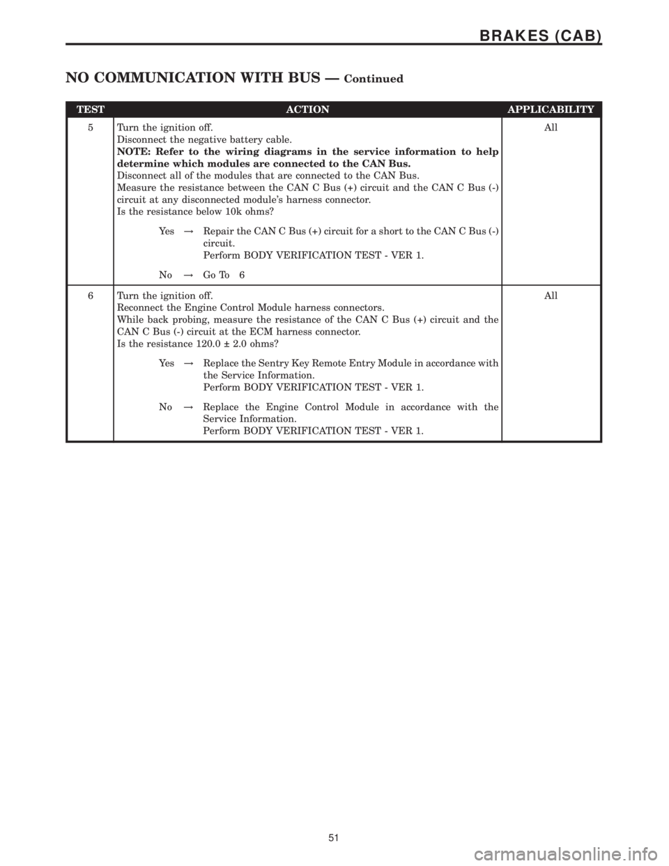
5 Turn the ignition off.
Disconnect the negative battery cable.
NOTE: Refer to the wiring diagrams in the service information to help
determine which modules are connected to the CAN Bus.
Disconnect all of the modules that are connected to the CAN Bus.
Measure the resistance between the CAN C Bus (+) circuit and the CAN C Bus (-)
circuit at any disconnected module's harness connector.
Is the resistance below 10k ohms?All
Ye s!Repair the CAN C Bus (+) circuit for a short to the CAN C Bus (-)
circuit.
Perform BODY VERIFICATION TEST - VER 1.
No!Go To 6
6 Turn the ignition off.
Reconnect the Engine Control Module harness connectors.
While back probing, measure the resistance of the CAN C Bus (+) circuit and the
CAN C Bus (-) circuit at the ECM harness connector.
Is the resistance 120.0 2.0 ohms?All
Ye s!Replace the Sentry Key Remote Entry Module in accordance with
the Service Information.
Perform BODY VERIFICATION TEST - VER 1.
No!Replace the Engine Control Module in accordance with the
Service Information.
Perform BODY VERIFICATION TEST - VER 1.
51
BRAKES (CAB)
NO COMMUNICATION WITH BUS ÐContinued
Page 373 of 2305

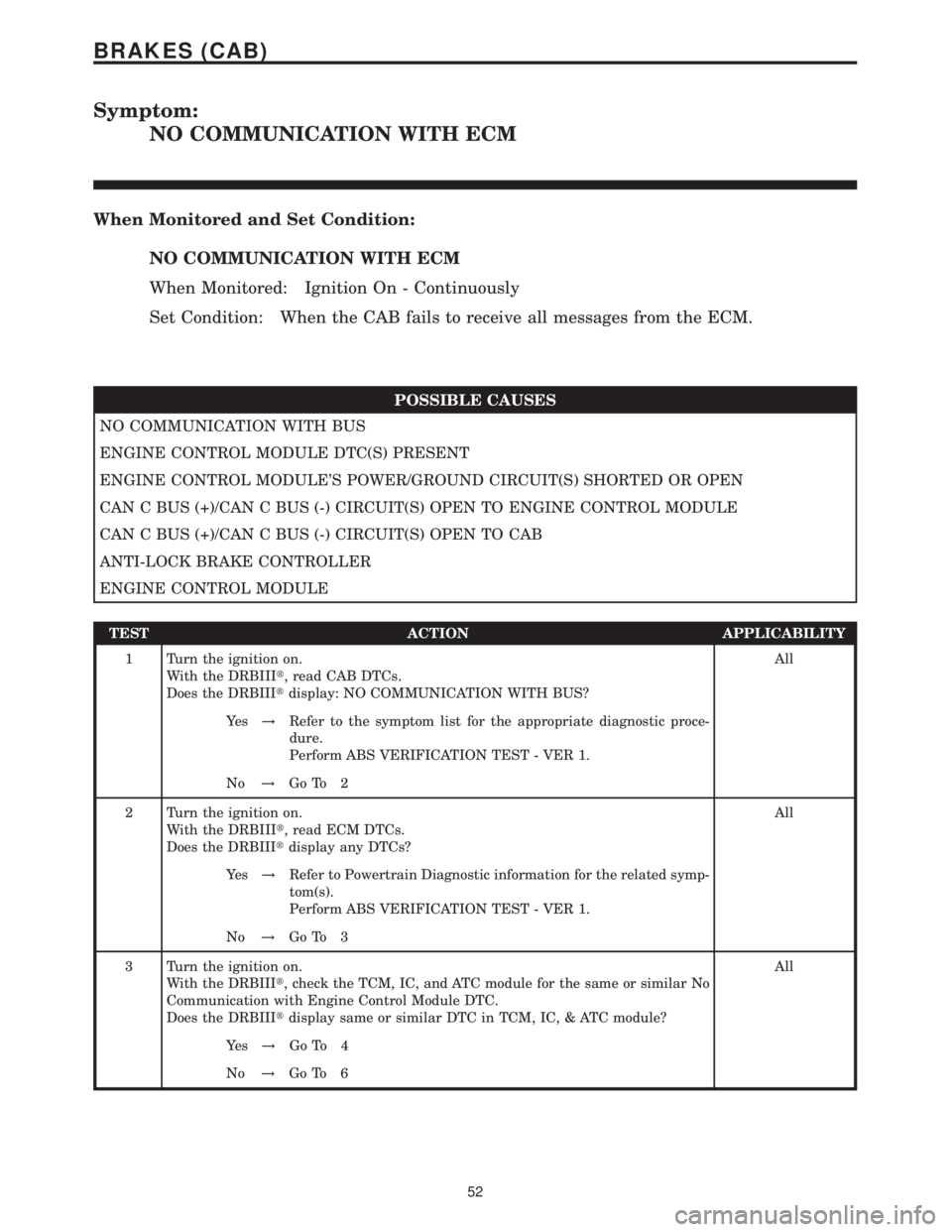
Symptom:
NO COMMUNICATION WITH ECM
When Monitored and Set Condition:
NO COMMUNICATION WITH ECM
When Monitored: Ignition On - Continuously
Set Condition: When the CAB fails to receive all messages from the ECM.
POSSIBLE CAUSES
NO COMMUNICATION WITH BUS
ENGINE CONTROL MODULE DTC(S) PRESENT
ENGINE CONTROL MODULE'S POWER/GROUND CIRCUIT(S) SHORTED OR OPEN
CAN C BUS (+)/CAN C BUS (-) CIRCUIT(S) OPEN TO ENGINE CONTROL MODULE
CAN C BUS (+)/CAN C BUS (-) CIRCUIT(S) OPEN TO CAB
ANTI-LOCK BRAKE CONTROLLER
ENGINE CONTROL MODULE
TEST ACTION APPLICABILITY
1 Turn the ignition on.
With the DRBIIIt, read CAB DTCs.
Does the DRBIIItdisplay: NO COMMUNICATION WITH BUS?All
Ye s!Refer to the symptom list for the appropriate diagnostic proce-
dure.
Perform ABS VERIFICATION TEST - VER 1.
No!Go To 2
2 Turn the ignition on.
With the DRBIIIt, read ECM DTCs.
Does the DRBIIItdisplay any DTCs?All
Ye s!Refer to Powertrain Diagnostic information for the related symp-
tom(s).
Perform ABS VERIFICATION TEST - VER 1.
No!Go To 3
3 Turn the ignition on.
With the DRBIIIt, check the TCM, IC, and ATC module for the same or similar No
Communication with Engine Control Module DTC.
Does the DRBIIItdisplay same or similar DTC in TCM, IC, & ATC module?All
Ye s!Go To 4
No!Go To 6
52
BRAKES (CAB)