2006 MERCEDES-BENZ SPRINTER charging
[x] Cancel search: chargingPage 893 of 2305

STARTING SYSTEM
TABLE OF CONTENTS
page page
STARTING SYSTEM
DESCRIPTION.........................28
OPERATION...........................28
DIAGNOSIS AND TESTING - STARTING
SYSTEM............................29
SPECIFICATIONS
TORQUE - STARTER - DIESEL...........33
SPECIFICATIONS - STARTER MOTOR -
DIESEL.............................33STARTER MOTOR
DIAGNOSIS AND TESTING - STARTER
MOTOR .............................33
REMOVAL.............................34
INSTALLATION.........................35
STARTER MOTOR RELAY
DESCRIPTION.........................35
REMOVAL.............................35
INSTALLATION.........................36
STARTING SYSTEM
DESCRIPTION
The starting system consists of:
²Starter relay
²Starter motor (including an integral starter sole-
noid)
Other components to be considered as part of start-
ing system are:
²Battery
²Battery cables
²Ignition switch and key lock cylinder
²Park/neutral position switch (automatic trans-
mission)
²Wire harnesses and connections.
The Battery, Starting, and Charging systems oper-
ate in conjunction with one another, and must be
tested as a complete system. For correct operation of
starting/charging systems, all components used in
these 3 systems must perform within specifications.
When attempting to diagnose any of these systems, it
is important that you keep their interdependency in
mind.
The diagnostic procedures used in each of these
groups include the most basic conventional diagnostic
methods, to the more sophisticated On-Board Diag-
nostics (OBD) built into the Engine Control Module
(ECM). Use of an induction-type milliampere amme-
ter, volt/ohmmeter, battery charger, carbon pile rheo-
stat (load tester), and 12-volt test lamp may be
required.
Certain starting system components are monitored
by the ECM and may produce a Diagnostic Trouble
Code (DTC).
OPERATION
The starting system components form two separate
circuits. A high-amperage feed circuit that feeds the
starter motor high-amperage, and a low-amperagecontrol circuit that operates on less than 20 amperes.
The high-amperage feed circuit components include
the battery, the battery cables, the contact disc por-
tion of the starter solenoid, and the starter motor
itself. The low-amperage control circuit components
include the ignition switch, the park/neutral position
switch (automatic transmission), the starter relay,
the electromagnetic windings of the starter solenoid,
and the connecting wire harness components.
If the vehicle is equipped with an automatic trans-
mission, battery voltage is supplied through the low-
amperage control circuit to the coil battery terminal
of the starter relay when the ignition switch is
turned to the momentary Start position. The park/
neutral position switch is installed in series between
the starter relay coil ground terminal and ground.
This normally open switch prevents the starter relay
from being energized and the starter motor from
operating unless the automatic transmission gear
selector is in the Neutral or Park positions.
When the starter relay coil is energized, the nor-
mally open relay contacts close. The relay contacts
connect the relay common feed terminal to the relay
normally open terminal. The closed relay contacts
energize the starter solenoid coil windings.
The energized solenoid pull-in coil pulls in the sole-
noid plunger. The solenoid plunger pulls the shift
lever in the starter motor. This engages the starter
overrunning clutch and pinion gear with the starter
ring gear on the manual transmission flywheel or on
the automatic transmission torque converter or
torque converter drive plate.
As the solenoid plunger reaches the end of its
travel, the solenoid contact disc completes the high-
amperage starter feed circuit and energizes the sole-
noid plunger hold-in coil. Current now flows between
the solenoid battery terminal and the starter motor,
energizing the starter.
Once the engine starts, the overrunning clutch pro-
tects the starter motor from damage by allowing the
8F - 28 STARTING SYSTEMVA
Page 894 of 2305
starter pinion gear to spin faster than the pinion
shaft. When the driver releases the ignition switch to
the On position, the starter relay coil is de-energized.
This causes the relay contacts to open. When the
relay contacts open, the starter solenoid plunger
hold-in coil is de-energized.
When the solenoid plunger hold-in coil is de-ener-
gized, the solenoid plunger return spring returns the
plunger to its relaxed position. This causes the con-
tact disc to open the starter feed circuit, and the shift
lever to disengage the overrunning clutch and pinion
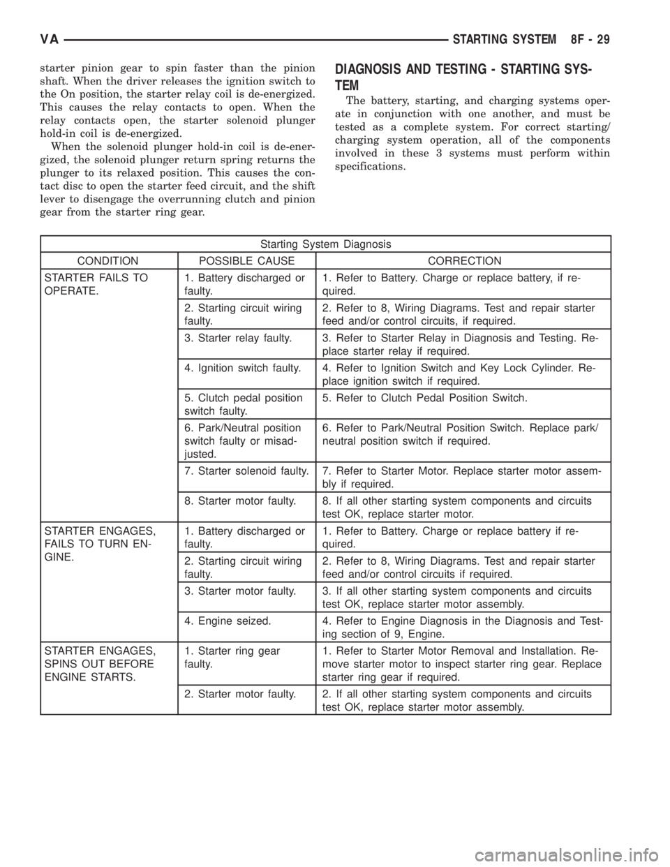
gear from the starter ring gear.DIAGNOSIS AND TESTING - STARTING SYS-
TEM
The battery, starting, and charging systems oper-
ate in conjunction with one another, and must be
tested as a complete system. For correct starting/
charging system operation, all of the components
involved in these 3 systems must perform within
specifications.
Starting System Diagnosis
CONDITION POSSIBLE CAUSE CORRECTION
STARTER FAILS TO
OPERATE.1. Battery discharged or
faulty.1. Refer to Battery. Charge or replace battery, if re-
quired.
2. Starting circuit wiring
faulty.2. Refer to 8, Wiring Diagrams. Test and repair starter
feed and/or control circuits, if required.
3. Starter relay faulty. 3. Refer to Starter Relay in Diagnosis and Testing. Re-
place starter relay if required.
4. Ignition switch faulty. 4. Refer to Ignition Switch and Key Lock Cylinder. Re-
place ignition switch if required.
5. Clutch pedal position
switch faulty.5. Refer to Clutch Pedal Position Switch.
6. Park/Neutral position
switch faulty or misad-
justed.6. Refer to Park/Neutral Position Switch. Replace park/
neutral position switch if required.
7. Starter solenoid faulty. 7. Refer to Starter Motor. Replace starter motor assem-
bly if required.
8. Starter motor faulty. 8. If all other starting system components and circuits
test OK, replace starter motor.
STARTER ENGAGES,
FAILS TO TURN EN-
GINE.1. Battery discharged or
faulty.1. Refer to Battery. Charge or replace battery if re-
quired.
2. Starting circuit wiring
faulty.2. Refer to 8, Wiring Diagrams. Test and repair starter
feed and/or control circuits if required.
3. Starter motor faulty. 3. If all other starting system components and circuits
test OK, replace starter motor assembly.
4. Engine seized. 4. Refer to Engine Diagnosis in the Diagnosis and Test-
ing section of 9, Engine.
STARTER ENGAGES,
SPINS OUT BEFORE
ENGINE STARTS.1. Starter ring gear
faulty.1. Refer to Starter Motor Removal and Installation. Re-
move starter motor to inspect starter ring gear. Replace
starter ring gear if required.
2. Starter motor faulty. 2. If all other starting system components and circuits
test OK, replace starter motor assembly.
VASTARTING SYSTEM 8F - 29
Page 920 of 2305
INSTRUMENT CLUSTER
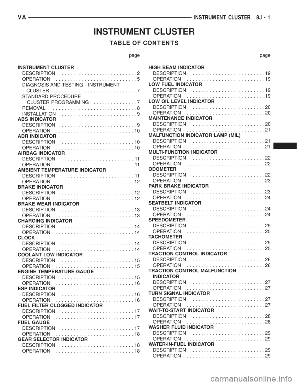
TABLE OF CONTENTS
page page
INSTRUMENT CLUSTER
DESCRIPTION..........................2
OPERATION............................5
DIAGNOSIS AND TESTING - INSTRUMENT
CLUSTER............................7
STANDARD PROCEDURE
CLUSTER PROGRAMMING...............7
REMOVAL.............................8
INSTALLATION..........................9
ABS INDICATOR
DESCRIPTION..........................9
OPERATION...........................10
ADR INDICATOR
DESCRIPTION.........................10
OPERATION...........................10
AIRBAG INDICATOR
DESCRIPTION.........................11
OPERATION...........................11
AMBIENT TEMPERATURE INDICATOR
DESCRIPTION.........................11
OPERATION...........................12
BRAKE INDICATOR
DESCRIPTION.........................12
OPERATION...........................12
BRAKE WEAR INDICATOR
DESCRIPTION.........................13
OPERATION...........................13
CHARGING INDICATOR
DESCRIPTION.........................14
OPERATION...........................14
CLOCK
DESCRIPTION.........................14
OPERATION...........................14
COOLANT LOW INDICATOR
DESCRIPTION.........................15
OPERATION...........................15
ENGINE TEMPERATURE GAUGE
DESCRIPTION.........................15
OPERATION...........................16
ESP INDICATOR
DESCRIPTION.........................16
OPERATION...........................16
FUEL FILTER CLOGGED INDICATOR
DESCRIPTION.........................17
OPERATION...........................17
FUEL GAUGE
DESCRIPTION.........................17
OPERATION...........................18
GEAR SELECTOR INDICATOR
DESCRIPTION.........................18
OPERATION...........................18HIGH BEAM INDICATOR
DESCRIPTION.........................19
OPERATION...........................19
LOW FUEL INDICATOR
DESCRIPTION.........................19
OPERATION...........................19
LOW OIL LEVEL INDICATOR
DESCRIPTION.........................20
OPERATION...........................20
MAINTENANCE INDICATOR
DESCRIPTION.........................20
OPERATION...........................21
MALFUNCTION INDICATOR LAMP (MIL)
DESCRIPTION.........................21
OPERATION...........................21
MULTI-FUNCTION INDICATOR
DESCRIPTION.........................22
OPERATION...........................22
ODOMETER
DESCRIPTION.........................22
OPERATION...........................23
PARK BRAKE INDICATOR
DESCRIPTION.........................23
OPERATION...........................24
SEATBELT INDICATOR
DESCRIPTION.........................24
OPERATION...........................24
SPEEDOMETER
DESCRIPTION.........................25
OPERATION...........................25
TACHOMETER
DESCRIPTION.........................25
OPERATION...........................25
TRACTION CONTROL INDICATOR
DESCRIPTION.........................26
OPERATION...........................26
TRACTION CONTROL MALFUNCTION
INDICATOR
DESCRIPTION.........................27
OPERATION...........................27
TURN SIGNAL INDICATOR
DESCRIPTION.........................27
OPERATION...........................27
WAIT-TO-START INDICATOR
DESCRIPTION.........................28
OPERATION...........................28
WASHER FLUID INDICATOR
DESCRIPTION.........................29
OPERATION...........................29
WATER-IN-FUEL INDICATOR
DESCRIPTION.........................29
OPERATION...........................29
VAINSTRUMENT CLUSTER 8J - 1
Page 922 of 2305

Located between the rear cover and the cluster
hood is the cluster housing. The molded plastic clus-
ter housing serves as the carrier for the cluster elec-
tronic circuit board and circuitry, the cluster
connector receptacles, the gauges, a Light Emitting
Diode (LED) for each cluster indicator and general
illumination lamp, the multi-function indicator LCD
unit, electronic tone generators, the cluster overlay,
the gauge pointers, the multi-function indicator
switches and the four switch push buttons.
The cluster overlay is a laminated plastic unit. The
dark, visible, outer surface of the overlay is marked
with all of the gauge dial faces and graduations, but
this layer is also translucent. The darkness of this
outer layer prevents the cluster from appearing clut-
tered or busy by concealing the cluster indicators
that are not illuminated, while the translucence of
this layer allows those indicators and icons that are
illuminated to be readily visible. The underlying
layer of the overlay is opaque and allows light from
the LED for each of the various indicators and illu-
mination lamps behind it to be visible through the
outer layer of the overlay only through predeter-
mined cutouts. A rectangular opening in the overlay
at the base of the speedometer provides a window
through which the illuminated multi-function indica-
tor LCD unit can be viewed.
Several versions of the EMIC module are offered
on this model. These versions accommodate all of the
variations of optional equipment and regulatory
requirements for the various markets in which the
vehicle will be offered. The microprocessor-based
EMIC utilizes integrated circuitry, Electrically Eras-
able Programmable Read Only Memory (EEPROM)
type memory storage, information carried on the
Controller Area Network (CAN) data bus, along with
several hard wired analog and multiplexed inputs to
monitor systems, sensors and switches throughout
the vehicle.
In response to those inputs, the hardware and soft-
ware of the EMIC allow it to control and integrate
many electronic functions and features of the vehicle
through both hard wired outputs and the transmis-
sion of electronic message outputs to other electronic
modules in the vehicle over the CAN data bus. (Refer
to 8 - ELECTRICAL/ELECTRONIC CONTROL
MODULES/COMMUNICATION - DESCRIPTION -
CAN BUS).
Besides typical instrument cluster gauge and indi-
cator support, the electronic functions and features
that the EMIC supports or controls include the fol-
lowing:
²Active Service System- In vehicles equipped
with the Active Service SYSTem (ASSYST) engine oil
maintenance indicator option, the EMIC electronic
circuit board includes a second dedicated micropro-
cessor. This second microprocessor evaluates various
data including time, mileage, and driving conditionsto calculate the required engine oil service intervals,
and provides both visual and audible alerts to the
vehicle operator when certain engine oil maintenance
services are required.
²Audible Warnings- The EMIC electronic cir-
cuit board is equipped with an audible tone generator
and programming that allows it to provide various
audible alerts to the vehicle operator, including buzz-
ing and chime tones. An audible contactless elec-
tronic relay is also soldered onto the circuit board to
produce audible clicks that is synchronized with turn
signal indicator flashing to emulate the sounds of a
conventional turn signal or hazard warning flasher.
These audible clicks can occur at one of two rates to
emulate both normal and bulb-out turn or hazard
flasher operation. (Refer to 8 - ELECTRICAL/
CHIME/BUZZER - DESCRIPTION).
²Panel Lamps Dimming Control- The EMIC
provides a hard wired 12-volt Pulse-Width Modulated
(PWM) output that synchronizes the dimming level
of all panel lamps dimmer controlled lamps with that
of the cluster general illumination lamps and multi-
function indicator.
The EMIC houses four analog gauges and has pro-
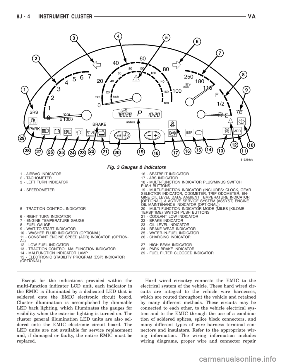
visions for up to nineteen indicators (Fig. 3). The
EMIC includes the following analog gauges:
²Coolant Temperature Gauge
²Fuel Gauge
²Speedometer
²Tachometer
The EMIC includes provisions for the following
indicators (Fig. 3):
²Airbag (SRS) Indicator
²Antilock Brake System (ABS) Indicator
²Brake Indicator
²Brake Wear Indicator
²Charging Indicator
²Clogged Fuel Filter Indicator
²Constant Engine Speed (ADR) Indicator
²Coolant Low Indicator
²Electronic Stability Program (ESP) Indica-
tor
²High Beam Indicator
²Low Fuel Indicator
²Malfunction Indicator Lamp (MIL)
²Multi-Function Indicator (LCD)
²Park Brake Indicator
²Seatbelt Indicator
²Traction Control (ASR) Indicator
²Traction Control (ASR) Malfunction Indica-
tor
²Turn Signal (Right and Left) Indicators
²Washer Fluid Indicator
²Wait-To-Start Indicator
²Water-In-Fuel Indicator
VAINSTRUMENT CLUSTER 8J - 3
Page 923 of 2305
Except for the indications provided within the
multi-function indicator LCD unit, each indicator in
the EMIC is illuminated by a dedicated LED that is
soldered onto the EMIC electronic circuit board.
Cluster illumination is accomplished by dimmable
LED back lighting, which illuminates the gauges for
visibility when the exterior lighting is turned on. The
cluster general illumination LED units are also sol-
dered onto the EMIC electronic circuit board. The
LED units are not available for service replacement
and, if damaged or faulty, the entire EMIC must be
replaced.Hard wired circuitry connects the EMIC to the
electrical system of the vehicle. These hard wired cir-
cuits are integral to the vehicle wire harnesses,
which are routed throughout the vehicle and retained
by many different methods. These circuits may be
connected to each other, to the vehicle electrical sys-
tem and to the EMIC through the use of a combina-
tion of soldered splices, splice block connectors, and
many different types of wire harness terminal con-
nectors and insulators. Refer to the appropriate wir-
ing information. The wiring information includes
wiring diagrams, proper wire and connector repair
Fig. 3 Gauges & Indicators
1 - AIRBAG INDICATOR 16 - SEATBELT INDICATOR
2 - TACHOMETER 17 - ABS INDICATOR
3 - LEFT TURN INDICATOR 18 - MULTI-FUNCTION INDICATOR PLUS/MINUS SWITCH
PUSH BUTTONS
4 - SPEEDOMETER 19 - MULTI-FUNCTION INDICATOR (INCLUDES: CLOCK, GEAR
SELECTOR INDICATOR, ODOMETER, TRIP ODOMETER, EN-
GINE OIL LEVEL DATA, AMBIENT TEMPERATURE INDICATOR
[OPTIONAL], & ACTIVE SERVICE SYSTEM [ASSYST] ENGINE
OIL MAINTENANCE INDICATOR [OPTIONAL])
5 - TRACTION CONTROL INDICATOR 20 - MULTI-FUNCTION INDICATOR MODE (MILES [KILOME-
TERS]/TIME) SWITCH PUSH BUTTONS
6 - RIGHT TURN INDICATOR 21 - COOLANT LOW INDICATOR
7 - ENGINE TEMPERATURE GAUGE 22 - BRAKE INDICATOR
8 - FUEL GAUGE 23 - OIL LEVEL INDICATOR
9 - WAIT-TO-START INDICATOR 24 - BRAKE WEAR INDICATOR
10 - WASHER FLUID INDICATOR (OPTIONAL) 25 - WATER-IN-FUEL INDICATOR
11 - CONSTANT ENGINE SPEED (ADR) INDICATOR (OPTION-
AL)26 - CHARGING INDICATOR
12 - LOW FUEL INDICATOR 27 - HIGH BEAM INDICATOR
13 - TRACTION CONTROL MALFUNCTION INDICATOR 28 - PARK BRAKE INDICATOR
14 - MALFUNCTION INDICATOR LAMP 29 - FUEL FILTER CLOGGED INDICATOR
15 - ELECTRONIC STABILITY PROGRAM (ESP) INDICATOR
(OPTIONAL)
8J - 4 INSTRUMENT CLUSTERVA
Page 925 of 2305

INDICATORS
Indicators are located in various positions within
the EMIC and are all connected to the EMIC elec-
tronic circuit board. The ambient temperature indica-
tor (optional), brake indicator, brake wear indicator,
charging indicator, coolant low indicator, high beam
indicator, low fuel indicator, park brake indicator,
seatbelt indicator, turn signal indicators, and washer
fluid indicator operate based upon hard wired inputs
to the EMIC. The airbag (SRS) indicator is normally
controlled by a hard wired input from the Airbag
Control Module (ACM); however, if the EMIC sees an
abnormal or no input from the ACM, it will automat-
ically turn the airbag indicator On until the hard
wired input from the ACM has been restored. The
Malfunction Indicator Lamp (MIL) is normally con-
trolled by CAN data bus messages from the Engine
Control Module (ECM); however, if the EMIC loses
CAN data bus communication, the EMIC circuitry
will automatically turn the MIL on until CAN data
bus communication is restored. The EMIC uses CAN
data bus messages from the ECM, the ACM, and the
Controller Antilock Brake to control all of the
remaining indicators.
The various EMIC indicators are controlled by dif-
ferent strategies; some receive battery feed from the
EMIC circuitry and have a switched ground, while
others are grounded through the EMIC circuitry and
have a switched battery feed. However, all indicators
are completely controlled by the EMIC microproces-
sor based upon various hard wired and electronic
message inputs. Except for the indications provided
by the multi-function indicator Liquid Crystal Dis-
play (LCD) unit, all indicators are illuminated at a
fixed intensity, which is not affected by the selected
illumination intensity of the EMIC general illumina-
tion lamps.
The hard wired indicator inputs may be diagnosed
using conventional diagnostic methods. However,
proper testing of the EMIC circuitry and the CAN
bus message controlled indicators requires the use of
a diagnostic scan tool. Refer to the appropriate diag-
nostic information. Specific details of the operation
for each indicator may be found elsewhere in this
service information.
CLUSTER ILLUMINATION
The EMIC has several general illumination lamps
that are illuminated when the exterior lighting is
turned on with the multi-function switch. The illumi-
nation intensity of these lamps is adjusted by a dim-
ming level input received from the multi-function
indicator ª+º (plus) and ª±º (minus) switch push but-
tons that extend through the lower edge of the clus-
ter lens below the right end of the multi-function
indicator. When the exterior lighting is turned Off,
the display is illuminated at maximum brightness.
When the exterior lighting is turned On and thetransmission gear selector is in the Park position,
depressing the plus switch push button brightens the
display lighting, and depressing the minus switch
push button dims the display lighting. The EMIC
also provides a Pulse-Width Modulated (PWM) panel
lamps dimmer output that can be used to synchro-
nize the illumination lighting levels of external illu-
mination lamps (up to about 23 to 30 watts) with
that of the EMIC.
The hard wired multi-function switch input and
the EMIC panel lamps dimmer output may be diag-
nosed using conventional diagnostic methods. How-
ever, proper testing of the PWM control of the EMIC
and the electronic dimming level inputs from the
multi-function indicator push buttons requires the
use of a diagnostic scan tool. Refer to the appropriate
diagnostic information.
INPUT AND OUTPUT CIRCUITS
HARD WIRED INPUTS
The hard wired inputs to the EMIC include the fol-
lowing:
NOTE: Final approved circuit names were not yet
available at the time this information was compiled.
²Airbag Indicator Driver
²Ambient Temperature Sensor Signal
(Optional)
²Brake Wear Indicator Sense
²Charging Indicator Driver
²Coolant Level Switch Sense
²Front Door Jamb Switch Sense
²Fuel Level Sensor Signal
²Fused B(+)
²Fused Ignition Switch Output
²High Beam Indicator Driver
²Key-In Ignition Switch Sense
²Left Turn Signal
²Park Brake Switch Sense
²Right Turn Signal
²Seat Belt Switch Sense
²Washer Fluid Switch Sense (Optional)
Refer to the appropriate wiring information for
additional details.
HARD WIRED OUTPUTS
The hard wired outputs of the EMIC include the
following:
²Engine Running Relay Control
²Panel Lamps Driver
Refer to the appropriate wiring information for
additional details.
8J - 6 INSTRUMENT CLUSTERVA
Page 933 of 2305

or until the ignition switch is turned to the Off posi-
tion, whichever occurs first.
A brake wear sensor located at each wheel provides
a hard wired ground input to the instrument cluster
circuitry through the brake wear sense circuit when-
ever the brake linings for that wheel have exceeded
their wear limits. The four normally open brake wear
sensors are connected in parallel between ground and
instrument cluster. The brake wear sensors and their
input circuit to the instrument cluster can be diag-
nosed using conventional diagnostic tools and meth-
ods. For proper diagnosis of the instrument cluster
circuitry that controls the brake wear indicator, a
diagnostic scan tool is required. Refer to the appro-
priate diagnostic information.
CHARGING INDICATOR
DESCRIPTION
A charging indicator is standard equipment on all
instrument clusters. The charging indicator is located
near the lower edge of the instrument cluster, to the
left of the multi-function indicator display. The
charging indicator consists of the International Con-
trol and Display Symbol icon for ªBattery Charging
Conditionº imprinted within a rectangular cutout in
the opaque layer of the instrument cluster overlay.
The dark outer layer of the overlay prevents the indi-
cator from being clearly visible when it is not illumi-
nated. A red Light Emitting Diode (LED) behind the
cutout in the opaque layer of the overlay causes the
icon to appear silhouetted against a red field through
the translucent outer layer of the overlay when the
indicator is illuminated from behind by the LED,
which is soldered onto the instrument cluster elec-
tronic circuit board. The charging indicator is ser-
viced as a unit with the instrument cluster.
OPERATION
The charging indicator gives an indication to the
vehicle operator when the electrical system voltage is
too low. This indicator is controlled by a transistor on
the instrument cluster circuit board based upon clus-
ter programming and a hard wired input from the
generator. The charging indicator Light Emitting
Diode (LED) is completely controlled by the instru-
ment cluster logic circuit, and that logic will only
allow this indicator to operate when the instrument
cluster detects that the ignition switch is in the On
position. Therefore, the LED will always be off when
the ignition switch is in any position except On. The
LED only illuminates when it is provided a path to
ground by the instrument cluster transistor. The
instrument cluster will turn on the charging indica-
tor for the following reasons:
²Bulb Test- Each time the ignition switch is
turned to the On position with the engine not run-ning the charging indicator is illuminated by the
instrument cluster as a bulb test.
²Generator Input- Each time the cluster
detects that the voltage of the generator input is 12.7
volts or lower while the engine is running, the charg-
ing indicator will be illuminated. The indicator
remains illuminated until the cluster detects that the
voltage of the generator input is above 12.7 volts, or
until the ignition switch is turned to the Off position,
whichever occurs first.
The generator provides a hard wired input to the
instrument cluster circuitry on the engine running
(D+) circuit. If the instrument cluster turns on the
indicator while the engine is running, it may indicate
that the charging system requires service. The gener-
ator input circuit to the instrument cluster can be
diagnosed using conventional diagnostic tools and
methods. For proper diagnosis of the charging sys-
tem, or the instrument cluster circuitry that controls
the charging indicator, a diagnostic scan tool is
required. Refer to the appropriate diagnostic infor-
mation.
CLOCK
DESCRIPTION
An electronic digital clock is standard equipment
on all instrument clusters. In vehicles equipped with
the optional ambient temperature indicator, the clock
indication can be toggled with the ambient tempera-
ture indication on the right side of the multi-function
indicator Liquid Crystal Display (LCD) located near
the lower edge of the instrument cluster, directly
below the speedometer. The clock provides a 12 hour-
based, digital indication of the current hours and
minutes. The indications of the clock are not visible
when the LCD is not illuminated. When illuminated
the indications appear as dark characters silhouetted
against an amber field. When the exterior lighting is
turned Off, the display is illuminated at maximum
brightness. When the exterior lighting is turned On
the display illumination level can be adjusted in con-
cert with the cluster general illumination lighting
using the ª+º (plus) and ª2º (minus) multi-function
indicator push buttons. The clock is serviced as a
unit with the instrument cluster.
OPERATION
The clock gives an indication to the vehicle opera-
tor of the current time. The electronic digital clock is
controlled by the instrument cluster microprocessor
based upon cluster programming. The clock display is
completely controlled by the instrument cluster logic
circuit, and that logic will only allow this indication
to be viewed when the multi-function indicator Liq-
uid Crystal Display (LCD) is activated. However, the
8J - 14 INSTRUMENT CLUSTERVA
Page 1080 of 2305
WIRING
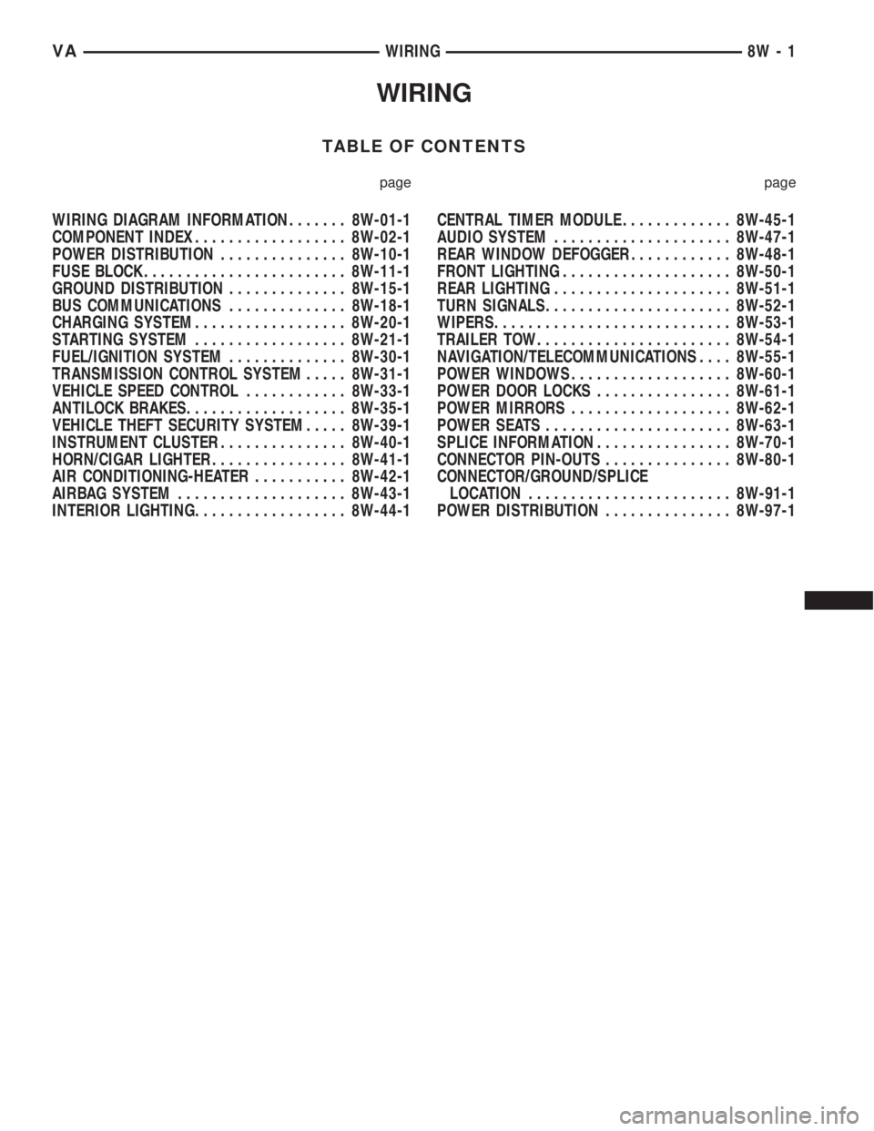
TABLE OF CONTENTS
page page
WIRING DIAGRAM INFORMATION....... 8W-01-1
COMPONENT INDEX.................. 8W-02-1
POWER DISTRIBUTION............... 8W-10-1
FUSE BLOCK........................ 8W-11-1
GROUND DISTRIBUTION.............. 8W-15-1
BUS COMMUNICATIONS.............. 8W-18-1
CHARGING SYSTEM.................. 8W-20-1
STARTING SYSTEM.................. 8W-21-1
FUEL/IGNITION SYSTEM.............. 8W-30-1
TRANSMISSION CONTROL SYSTEM..... 8W-31-1
VEHICLE SPEED CONTROL............ 8W-33-1
ANTILOCK BRAKES................... 8W-35-1
VEHICLE THEFT SECURITY SYSTEM..... 8W-39-1
INSTRUMENT CLUSTER............... 8W-40-1
HORN/CIGAR LIGHTER................ 8W-41-1
AIR CONDITIONING-HEATER........... 8W-42-1
AIRBAG SYSTEM.................... 8W-43-1
INTERIOR LIGHTING.................. 8W-44-1CENTRAL TIMER MODULE............. 8W-45-1
AUDIO SYSTEM..................... 8W-47-1
REAR WINDOW DEFOGGER............ 8W-48-1
FRONT LIGHTING.................... 8W-50-1
REAR LIGHTING..................... 8W-51-1
TURN SIGNALS...................... 8W-52-1
WIPERS............................ 8W-53-1
TRAILER TOW....................... 8W-54-1
NAVIGATION/TELECOMMUNICATIONS.... 8W-55-1
POWER WINDOWS................... 8W-60-1
POWER DOOR LOCKS................ 8W-61-1
POWER MIRRORS................... 8W-62-1
POWER SEATS...................... 8W-63-1
SPLICE INFORMATION................ 8W-70-1
CONNECTOR PIN-OUTS............... 8W-80-1
CONNECTOR/GROUND/SPLICE
LOCATION........................ 8W-91-1
POWER DISTRIBUTION............... 8W-97-1 VAWIRING 8W - 1