2006 MERCEDES-BENZ SPRINTER battery replacement
[x] Cancel search: battery replacementPage 1064 of 2305
WASHER RESERVOIR
DESCRIPTION
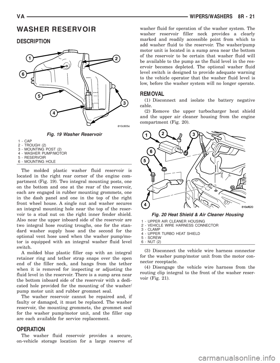
The molded plastic washer fluid reservoir is
located in the right rear corner of the engine com-
partment (Fig. 19). Two integral mounting posts, one
on the bottom and one at the rear of the reservoir,
each are engaged in rubber mounting grommets, one
in the dash panel and one in the top of the right
front wheel house. A single nut and washer secures
an integral mounting hole near the top of the reser-
voir to a stud nut on the right inner fender shield.
Also near the upper inboard side of the reservoir are
two integral hose routing troughs, one for the stan-
dard washer supply hose and the second for the
optional vent hose used when the washer pump/mo-
tor is equipped with an integral washer fluid level
switch.
A molded blue plastic filler cap with an integral
retainer ring and tether strap snaps over the open
end of the filler neck, and hangs from the tether
when it is removed for inspecting or adjusting the
fluid level in the reservoir. There is a sump area near
the bottom inboard side of the reservoir with a dedi-
cated hole provided for the mounting of the washer/
pump motor unit and rubber grommet seal.
The washer reservoir cannot be repaired and, if
faulty or damaged, it must be replaced. The washer
reservoir, the mounting grommets, the grommet seal
for the washer pump/motor unit, and the filler cap
are each available for service replacement.
OPERATION
The washer fluid reservoir provides a secure,
on-vehicle storage location for a large reserve ofwasher fluid for operation of the washer system. The
washer reservoir filler neck provides a clearly
marked and readily accessible point from which to
add washer fluid to the reservoir. The washer/pump
motor unit is located in a sump area near the bottom
of the reservoir to be certain that washer fluid will
be available to the pump as the fluid level in the res-
ervoir becomes depleted. The optional washer fluid
level switch is designed to provide adequate warning
to the vehicle operator that the washer fluid level is
low, before the washer system will no longer operate.
REMOVAL
(1) Disconnect and isolate the battery negative
cable.
(2) Remove the upper turbocharger heat shield
and the upper air cleaner housing from the engine
compartment (Fig. 20).
(3) Disconnect the vehicle wire harness connector
for the washer pump/motor unit from the motor con-
nector receptacle.
(4) Disengage the vehicle wire harness from the
routing clip integral to the front of the washer reser-
voir (Fig. 21).
Fig. 19 Washer Reservoir
1 - CAP
2 - TROUGH (2)
3 - MOUNTING POST (2)
4 - WASHER PUMP/MOTOR
5 - RESERVOIR
6 - MOUNTING HOLE
Fig. 20 Heat Shield & Air Cleaner Housing
1 - UPPER AIR CLEANER HOUSING
2 - VEHICLE WIRE HARNESS CONNECTOR
3 - CLAMP
4 - UPPER TURBO HEAT SHIELD
5 - SCREW
6 - NUT (2)
VAWIPERS/WASHERS 8R - 21
Page 1691 of 2305
FUEL DRAIN TUBES
DIAGNOSIS AND TESTING - FUEL SUPPLY
RESTRICTIONS
LOW - PRESSURE LINES
Fuel supply line restrictions can cause starting
problems and prevent engine from accelerating. The
starting problems include; low power and/or white
fog like exhaust.
Test all fuel supply lines for restrictions or block-
age. Flush or replace as necessary.
HIGH - PRESSURE LINES
CAUTION: High pressure lines cannot contact each
other or other components. Do not attempt to weld
high-pressure fuel lines or to repair lines that are
damaged. High pressure lines must be replaced at
each disassembly. Use only recommended lines
when replacement of high-pressure fuel line is nec-
essary.
Restricted (kinked or bent) high-pressure lines can
cause starting problems, poor engine performance,engine mis-fire and white smoke from exhaust (Refer
to 14 - FUEL SYSTEM - WARNING).
FUEL FILTER
DESCRIPTION
The fuel filter was designed for improved high alti-
tude operation and for better re-start after the fuel
tank has been completely emptied. The water drain
plug and water in fuel (WIF) sensor are located on
the top of the filter. Water is drained by using the in-
tank electric fuel pump to generate flow (attach a
hose to the drain plug). The filter has a pressure dif-
ferential of 200±300 mbar (2.9 psi.) when new. When
dirty, the pressure differential rises to 800 mbar (11.6
psi.) (Fig. 2).
REMOVAL
WARNING: NO SPARKS, OPEN FLAMES OR SMOK-
ING. RISK OF POISONING FROM INHALING AND
SWALLOWING FUEL. RISK OF INJURY TO EYES
AND SKIN FROM CONTACT WITH FUEL. POUR
FUELS ONLY INTO SUITABLE AND APPROPRI-
ATELY MARKED CONTAINERS. WEAR PROTECTIVE
CLOTHING.
CAUTION: DO NOT bend, twist or cut the fuel hose
clamps. The fuel hose clamps through out the fuel
system are reusable when using special tool #9539.
Orginal clamps must be used when servicing the
fuel system.
(1) Disconnect negative battery cable.
(2) Disconnect the water in fuel (WIF) sensor har-
ness connector (Fig. 2).
(3) Release the fuel inlet and outlet hose clamps
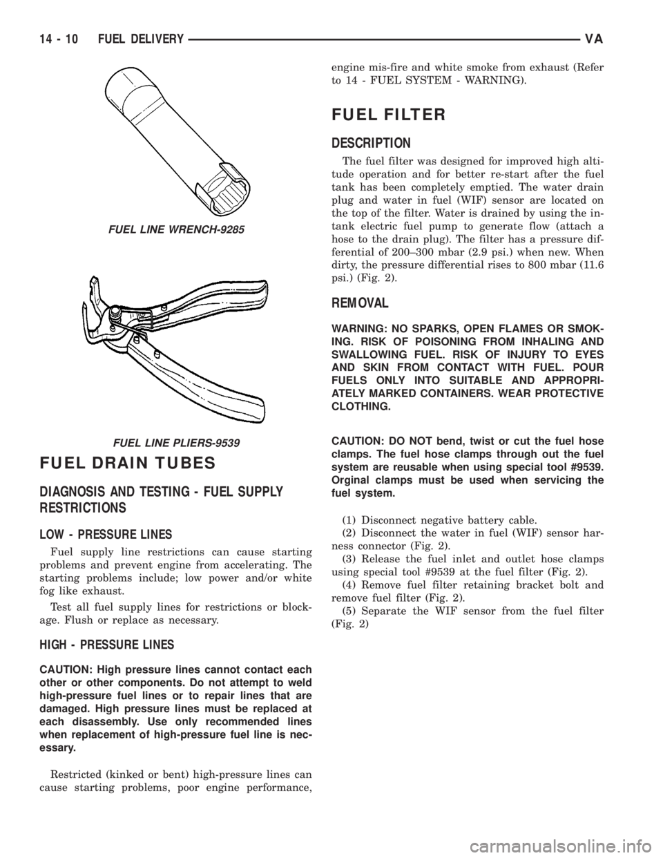
using special tool #9539 at the fuel filter (Fig. 2).
(4) Remove fuel filter retaining bracket bolt and
remove fuel filter (Fig. 2).
(5) Separate the WIF sensor from the fuel filter
(Fig. 2)
FUEL LINE WRENCH-9285
FUEL LINE PLIERS-9539
14 - 10 FUEL DELIVERYVA
Page 2002 of 2305
INSTRUMENT PANEL ASSEM-
BLY
REMOVAL
WARNING: ON VEHICLES EQUIPPED WITH AIR-
BAGS, DISABLE THE AIRBAG SYSTEM BEFORE
ATTEMPTING ANY STEERING WHEEL, STEERING
COLUMN, SEAT BELT TENSIONER, OR INSTRU-
MENT PANEL COMPONENT DIAGNOSIS OR SER-
VICE. DISCONNECT AND ISOLATE THE BATTERY
NEGATIVE (GROUND) CABLE, THEN WAIT TWO
MINUTES FOR THE AIRBAG SYSTEM CAPACITOR
TO DISCHARGE BEFORE PERFORMING FURTHER
DIAGNOSIS OR SERVICE. THIS IS THE ONLY SURE
WAY TO DISABLE THE AIRBAG SYSTEM. FAILURE
TO TAKE THE PROPER PRECAUTIONS COULD
RESULT IN ACCIDENTAL AIRBAG DEPLOYMENT
AND POSSIBLE PERSONAL INJURY.
²WHEN REMOVING A DEPLOYED AIRBAG, RUB-
BER GLOVES, EYE PROTECTION, AND A LONG-
SLEEVED SHIRT SHOULD BE WORN. THERE MAY
BE DEPOSITS ON THE AIRBAG UNIT AND OTHER
INTERIOR SURFACES. IN LARGE DOSES, THESE
DEPOSITS MAY CAUSE IRRITATION TO THE SKIN
AND EYES.
²USE EXTREME CARE TO PREVENT ANY FOR-
EIGN MATERIAL FROM ENTERING THE PASSEN-
GER AIRBAG, OR BECOMING ENTRAPPED
BETWEEN THE PASSENGER AIRBAG CUSHION
AND THE PASSENGER AIRBAG DOOR. FAILURE TO
OBSERVE THIS WARNING COULD RESULT IN
OCCUPANT INJURIES UPON AIRBAG DEPLOY-
MENT.
²THE PASSENGER AIRBAG DOOR MUST
NEVER BE PAINTED. REPLACEMENT PASSENGER
AIRBAGS ARE SERVICED WITH DOORS IN THE
ORIGINAL COLORS. PAINT MAY CHANGE THE WAY
IN WHICH THE MATERIAL OF THE AIRBAG DOOR
RESPONDS TO AN AIRBAG DEPLOYMENT. FAIL-
URE TO OBSERVE THIS WARNING COULD RESULT
IN OCCUPANT INJURIES UPON AIRBAG DEPLOY-
MENT.
(1) Disconnect and isolate the battery negative
cable.
(2) Remove radio. (Refer to 8 - ELECTRICAL/AU-
DIO/RADIO - REMOVAL)
(3) Remove glove compartment. (Refer to 23 -
BODY/INSTRUMENT PANEL/GLOVE BOX -
REMOVAL)
(4) Remove cup holder. (Refer to 23 - BODY/IN-
STRUMENT PANEL/CUP HOLDER - REMOVAL)
(5) Remove instrument cluster. (Refer to 8 - ELEC-
TRICAL/INSTRUMENT CLUSTER - REMOVAL)(6) Remove passenger airbag. (Refer to 8 - ELEC-
TRICAL/RESTRAINTS/PASSENGER AIRBAG -
REMOVAL)
(7) Remove right and left speakers. (Refer to 8 -
ELECTRICAL/AUDIO/SPEAKER - REMOVAL)
(8) Remove center bezel. (Refer to 23 - BODY/IN-
STRUMENT PANEL/INSTRUMENT PANEL CEN-
TER BEZEL - REMOVAL)
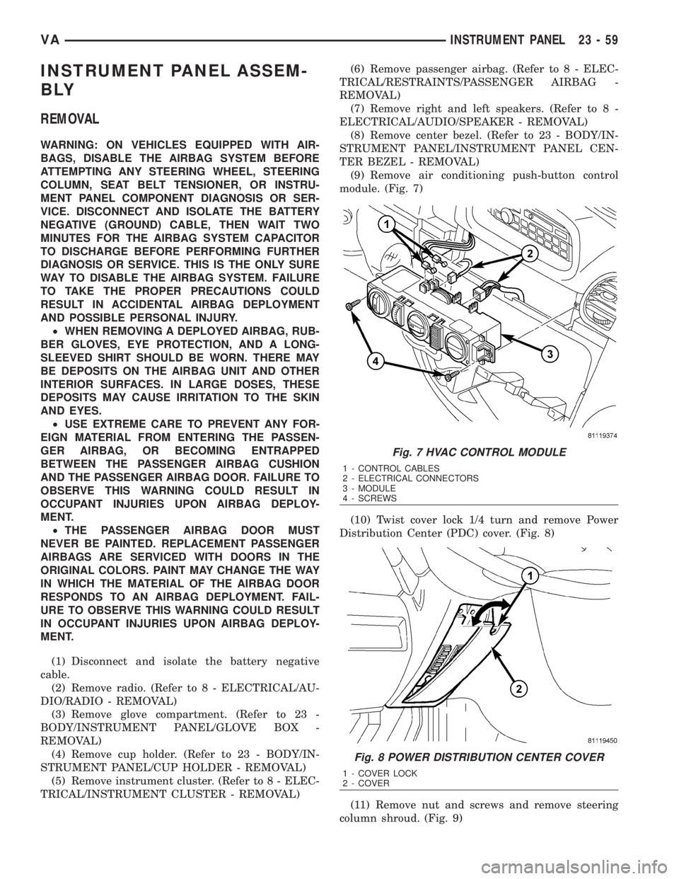
(9) Remove air conditioning push-button control
module. (Fig. 7)
(10) Twist cover lock 1/4 turn and remove Power
Distribution Center (PDC) cover. (Fig. 8)
(11) Remove nut and screws and remove steering
column shroud. (Fig. 9)
Fig. 7 HVAC CONTROL MODULE
1 - CONTROL CABLES
2 - ELECTRICAL CONNECTORS
3 - MODULE
4 - SCREWS
Fig. 8 POWER DISTRIBUTION CENTER COVER
1 - COVER LOCK
2 - COVER
VAINSTRUMENT PANEL 23 - 59
Page 2006 of 2305
INSTALLATION
WARNING: ON VEHICLES EQUIPPED WITH AIR-
BAGS, DISABLE THE AIRBAG SYSTEM BEFORE
ATTEMPTING ANY STEERING WHEEL, STEERING
COLUMN, SEAT BELT TENSIONER, OR INSTRU-
MENT PANEL COMPONENT DIAGNOSIS OR SER-
VICE. DISCONNECT AND ISOLATE THE BATTERY
NEGATIVE (GROUND) CABLE, THEN WAIT TWO
MINUTES FOR THE AIRBAG SYSTEM CAPACITOR
TO DISCHARGE BEFORE PERFORMING FURTHER
DIAGNOSIS OR SERVICE. THIS IS THE ONLY SURE
WAY TO DISABLE THE AIRBAG SYSTEM. FAILURE
TO TAKE THE PROPER PRECAUTIONS COULD
RESULT IN ACCIDENTAL AIRBAG DEPLOYMENT
AND POSSIBLE PERSONAL INJURY.
²WHEN REMOVING A DEPLOYED AIRBAG, RUB-
BER GLOVES, EYE PROTECTION, AND A LONG-
SLEEVED SHIRT SHOULD BE WORN. THERE MAY
BE DEPOSITS ON THE AIRBAG UNIT AND OTHER
INTERIOR SURFACES. IN LARGE DOSES, THESE
DEPOSITS MAY CAUSE IRRITATION TO THE SKIN
AND EYES.
²USE EXTREME CARE TO PREVENT ANY FOR-
EIGN MATERIAL FROM ENTERING THE PASSEN-
GER AIRBAG, OR BECOMING ENTRAPPED
BETWEEN THE PASSENGER AIRBAG CUSHION
AND THE PASSENGER AIRBAG DOOR. FAILURE TO
OBSERVE THIS WARNING COULD RESULT IN
OCCUPANT INJURIES UPON AIRBAG DEPLOY-
MENT.
²THE PASSENGER AIRBAG DOOR MUST
NEVER BE PAINTED. REPLACEMENT PASSENGER
AIRBAGS ARE SERVICED WITH DOORS IN THE
ORIGINAL COLORS. PAINT MAY CHANGE THE WAY
IN WHICH THE MATERIAL OF THE AIRBAG DOOR
RESPONDS TO AN AIRBAG DEPLOYMENT. FAIL-
URE TO OBSERVE THIS WARNING COULD RESULT
IN OCCUPANT INJURIES UPON AIRBAG DEPLOY-
MENT.
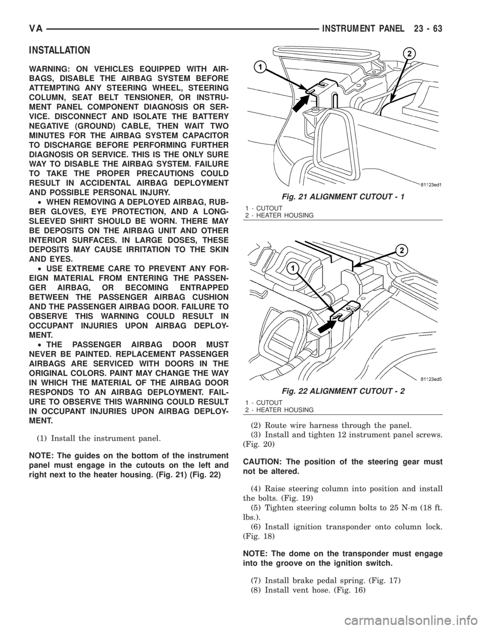
(1) Install the instrument panel.
NOTE: The guides on the bottom of the instrument
panel must engage in the cutouts on the left and
right next to the heater housing. (Fig. 21) (Fig. 22)(2) Route wire harness through the panel.
(3) Install and tighten 12 instrument panel screws.
(Fig. 20)
CAUTION: The position of the steering gear must
not be altered.
(4) Raise steering column into position and install
the bolts. (Fig. 19)
(5) Tighten steering column bolts to 25 N´m (18 ft.
lbs.).
(6) Install ignition transponder onto column lock.
(Fig. 18)
NOTE: The dome on the transponder must engage
into the groove on the ignition switch.
(7) Install brake pedal spring. (Fig. 17)
(8) Install vent hose. (Fig. 16)
Fig. 21 ALIGNMENT CUTOUT - 1
1 - CUTOUT
2 - HEATER HOUSING
Fig. 22 ALIGNMENT CUTOUT - 2
1 - CUTOUT
2 - HEATER HOUSING
VAINSTRUMENT PANEL 23 - 63
Page 2010 of 2305
TOP COVER
REMOVAL
WARNING: ON VEHICLES EQUIPPED WITH AIR-
BAGS, DISABLE THE AIRBAG SYSTEM BEFORE
ATTEMPTING ANY STEERING WHEEL, STEERING
COLUMN, SEAT BELT TENSIONER, OR INSTRU-
MENT PANEL COMPONENT DIAGNOSIS OR SER-
VICE. DISCONNECT AND ISOLATE THE BATTERY
NEGATIVE (GROUND) CABLE, THEN WAIT TWO
MINUTES FOR THE AIRBAG SYSTEM CAPACITOR
TO DISCHARGE BEFORE PERFORMING FURTHER
DIAGNOSIS OR SERVICE. THIS IS THE ONLY SURE
WAY TO DISABLE THE AIRBAG SYSTEM. FAILURE
TO TAKE THE PROPER PRECAUTIONS COULD
RESULT IN ACCIDENTAL AIRBAG DEPLOYMENT
AND POSSIBLE PERSONAL INJURY.
²WHEN REMOVING A DEPLOYED AIRBAG, RUB-
BER GLOVES, EYE PROTECTION, AND A LONG-
SLEEVED SHIRT SHOULD BE WORN. THERE MAY
BE DEPOSITS ON THE AIRBAG UNIT AND OTHER
INTERIOR SURFACES. IN LARGE DOSES, THESE
DEPOSITS MAY CAUSE IRRITATION TO THE SKIN
AND EYES.
²USE EXTREME CARE TO PREVENT ANY FOR-
EIGN MATERIAL FROM ENTERING THE PASSEN-
GER AIRBAG, OR BECOMING ENTRAPPED
BETWEEN THE PASSENGER AIRBAG CUSHION
AND THE PASSENGER AIRBAG DOOR. FAILURE TO
OBSERVE THIS WARNING COULD RESULT IN
OCCUPANT INJURIES UPON AIRBAG DEPLOY-
MENT.
²THE PASSENGER AIRBAG DOOR MUST
NEVER BE PAINTED. REPLACEMENT PASSENGER
AIRBAGS ARE SERVICED WITH DOORS IN THE
ORIGINAL COLORS. PAINT MAY CHANGE THE WAY
IN WHICH THE MATERIAL OF THE AIRBAG DOOR
RESPONDS TO AN AIRBAG DEPLOYMENT. FAIL-
URE TO OBSERVE THIS WARNING COULD RESULT
IN OCCUPANT INJURIES UPON AIRBAG DEPLOY-
MENT.
(1) Disconnect and isolate the battery negative
cable.
(2) Remove radio. (Refer to 8 - ELECTRICAL/AU-
DIO/RADIO - REMOVAL)
(3) Remove passenger airbag. (Refer to 8 - ELEC-
TRICAL/RESTRAINTS/PASSENGER AIRBAG -
REMOVAL)
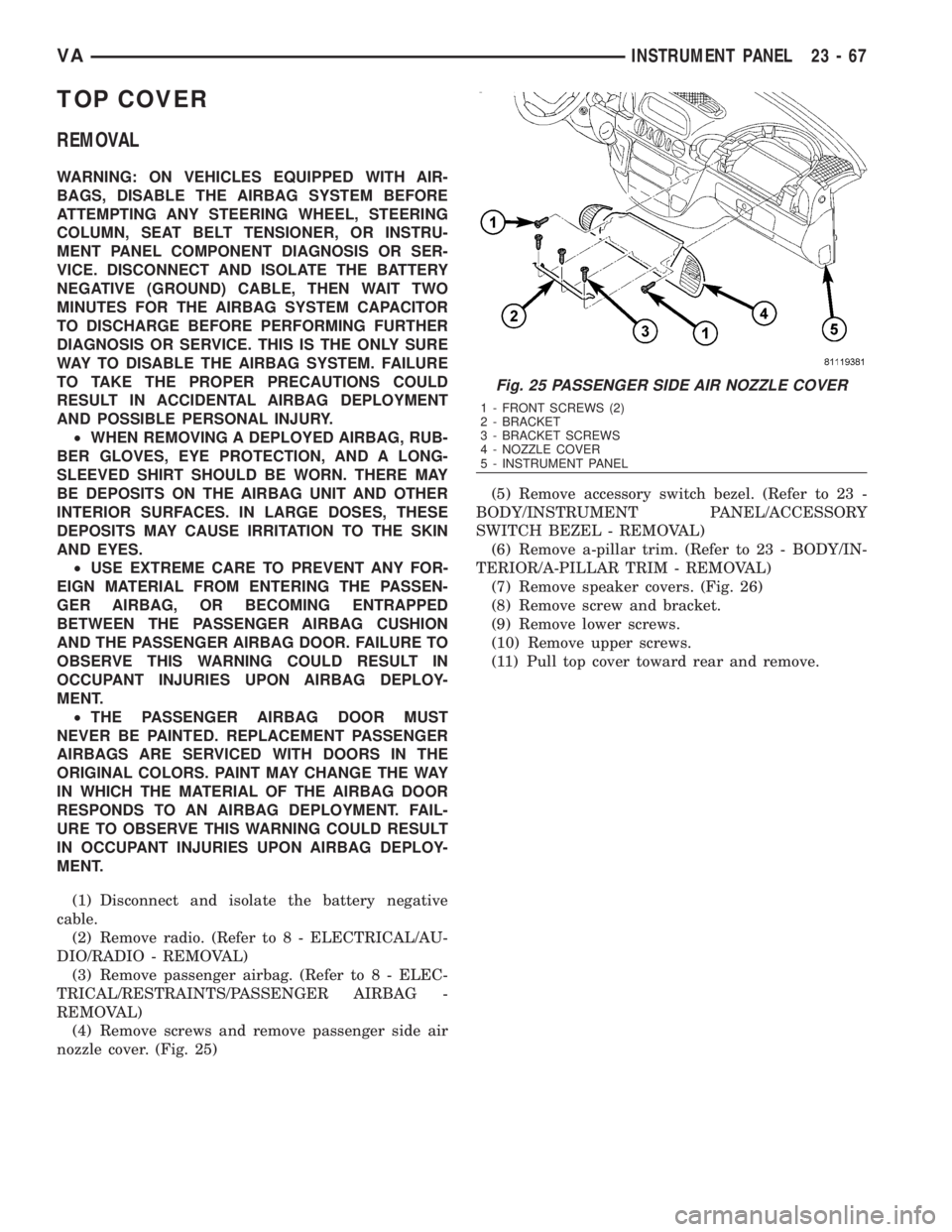
(4) Remove screws and remove passenger side air
nozzle cover. (Fig. 25)(5) Remove accessory switch bezel. (Refer to 23 -
BODY/INSTRUMENT PANEL/ACCESSORY
SWITCH BEZEL - REMOVAL)
(6) Remove a-pillar trim. (Refer to 23 - BODY/IN-
TERIOR/A-PILLAR TRIM - REMOVAL)
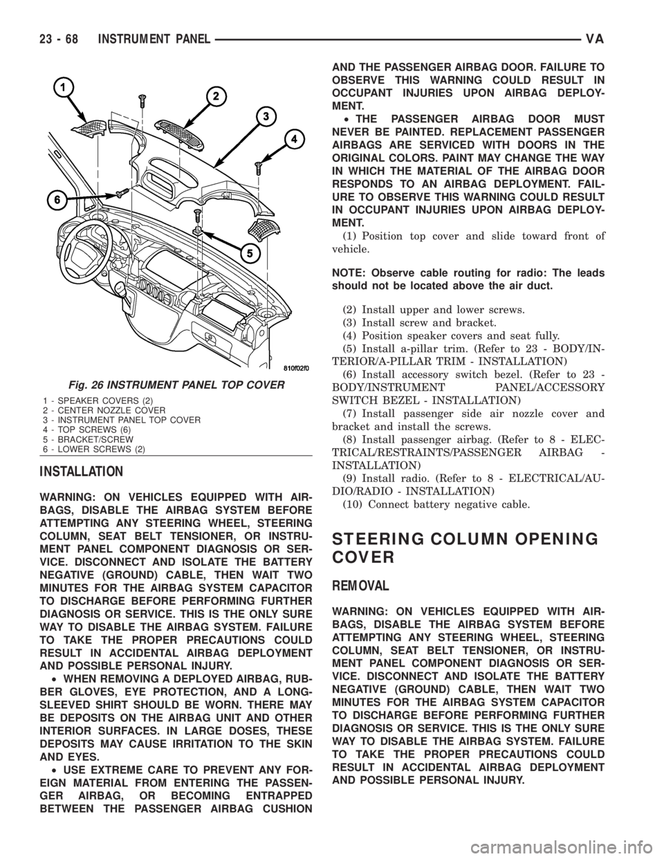
(7) Remove speaker covers. (Fig. 26)
(8) Remove screw and bracket.
(9) Remove lower screws.
(10) Remove upper screws.
(11) Pull top cover toward rear and remove.
Fig. 25 PASSENGER SIDE AIR NOZZLE COVER
1 - FRONT SCREWS (2)
2 - BRACKET
3 - BRACKET SCREWS
4 - NOZZLE COVER
5 - INSTRUMENT PANEL
VAINSTRUMENT PANEL 23 - 67
Page 2011 of 2305
INSTALLATION
WARNING: ON VEHICLES EQUIPPED WITH AIR-
BAGS, DISABLE THE AIRBAG SYSTEM BEFORE
ATTEMPTING ANY STEERING WHEEL, STEERING
COLUMN, SEAT BELT TENSIONER, OR INSTRU-
MENT PANEL COMPONENT DIAGNOSIS OR SER-
VICE. DISCONNECT AND ISOLATE THE BATTERY
NEGATIVE (GROUND) CABLE, THEN WAIT TWO
MINUTES FOR THE AIRBAG SYSTEM CAPACITOR
TO DISCHARGE BEFORE PERFORMING FURTHER
DIAGNOSIS OR SERVICE. THIS IS THE ONLY SURE
WAY TO DISABLE THE AIRBAG SYSTEM. FAILURE
TO TAKE THE PROPER PRECAUTIONS COULD
RESULT IN ACCIDENTAL AIRBAG DEPLOYMENT
AND POSSIBLE PERSONAL INJURY.
²WHEN REMOVING A DEPLOYED AIRBAG, RUB-
BER GLOVES, EYE PROTECTION, AND A LONG-
SLEEVED SHIRT SHOULD BE WORN. THERE MAY
BE DEPOSITS ON THE AIRBAG UNIT AND OTHER
INTERIOR SURFACES. IN LARGE DOSES, THESE
DEPOSITS MAY CAUSE IRRITATION TO THE SKIN
AND EYES.
²USE EXTREME CARE TO PREVENT ANY FOR-
EIGN MATERIAL FROM ENTERING THE PASSEN-
GER AIRBAG, OR BECOMING ENTRAPPED
BETWEEN THE PASSENGER AIRBAG CUSHIONAND THE PASSENGER AIRBAG DOOR. FAILURE TO
OBSERVE THIS WARNING COULD RESULT IN
OCCUPANT INJURIES UPON AIRBAG DEPLOY-
MENT.
²THE PASSENGER AIRBAG DOOR MUST
NEVER BE PAINTED. REPLACEMENT PASSENGER
AIRBAGS ARE SERVICED WITH DOORS IN THE
ORIGINAL COLORS. PAINT MAY CHANGE THE WAY
IN WHICH THE MATERIAL OF THE AIRBAG DOOR
RESPONDS TO AN AIRBAG DEPLOYMENT. FAIL-
URE TO OBSERVE THIS WARNING COULD RESULT
IN OCCUPANT INJURIES UPON AIRBAG DEPLOY-
MENT.
(1) Position top cover and slide toward front of
vehicle.
NOTE: Observe cable routing for radio: The leads
should not be located above the air duct.
(2) Install upper and lower screws.
(3) Install screw and bracket.
(4) Position speaker covers and seat fully.
(5) Install a-pillar trim. (Refer to 23 - BODY/IN-
TERIOR/A-PILLAR TRIM - INSTALLATION)
(6) Install accessory switch bezel. (Refer to 23 -
BODY/INSTRUMENT PANEL/ACCESSORY
SWITCH BEZEL - INSTALLATION)
(7) Install passenger side air nozzle cover and
bracket and install the screws.
(8) Install passenger airbag. (Refer to 8 - ELEC-
TRICAL/RESTRAINTS/PASSENGER AIRBAG -
INSTALLATION)
(9) Install radio. (Refer to 8 - ELECTRICAL/AU-
DIO/RADIO - INSTALLATION)
(10) Connect battery negative cable.
STEERING COLUMN OPENING
COVER
REMOVAL
WARNING: ON VEHICLES EQUIPPED WITH AIR-
BAGS, DISABLE THE AIRBAG SYSTEM BEFORE
ATTEMPTING ANY STEERING WHEEL, STEERING
COLUMN, SEAT BELT TENSIONER, OR INSTRU-
MENT PANEL COMPONENT DIAGNOSIS OR SER-
VICE. DISCONNECT AND ISOLATE THE BATTERY
NEGATIVE (GROUND) CABLE, THEN WAIT TWO
MINUTES FOR THE AIRBAG SYSTEM CAPACITOR
TO DISCHARGE BEFORE PERFORMING FURTHER
DIAGNOSIS OR SERVICE. THIS IS THE ONLY SURE
WAY TO DISABLE THE AIRBAG SYSTEM. FAILURE
TO TAKE THE PROPER PRECAUTIONS COULD
RESULT IN ACCIDENTAL AIRBAG DEPLOYMENT
AND POSSIBLE PERSONAL INJURY.
Fig. 26 INSTRUMENT PANEL TOP COVER
1 - SPEAKER COVERS (2)
2 - CENTER NOZZLE COVER
3 - INSTRUMENT PANEL TOP COVER
4 - TOP SCREWS (6)
5 - BRACKET/SCREW
6 - LOWER SCREWS (2)
23 - 68 INSTRUMENT PANELVA
Page 2046 of 2305
OPERATION
The compressor clutch components provide the
means to engage and disengage the compressor from
the engine serpentine accessory drive belt. When the
clutch coil is energized, it magnetically draws the
clutch into contact with the pulley and drives the
compressor shaft. When the coil is not energized, the
pulley freewheels on the clutch hub bearing, which is
part of the pulley.
The compressor clutch engagement is controlled by
several components:
²A/C switch on the A/C-heater control panel
²Evaporator temperature sensor
²A/C pressure transducer
²Air temperature sensor
²CAN bus messages
The compressor clutch is de-energized under any of
the following conditions:
²Blocked compressor (thermal fuse in the pulley)
²Low pressure in the system
²Low evaporator temperature
²Hard acceleration (WOT)
²High coolant temperatures
STANDARD PROCEDURE
A / C COMPRESSOR CLUTCH AIR GAP
If a new clutch plate and/or clutch pulley are being
used, the air gap between the clutch plate and clutch
pulley must be checked using the following proce-
dure:
(1) Using feeler gauges, measure the air gap
between the clutch plate and the clutch pulley fric-
tion surfaces.
(2) If the air gap is not between specifications
(Refer to 24 - HEATING & AIR CONDITIONING -
SPECIFICATIONS), add or subtract shims until the
desired air gap is obtained.
NOTE: The shims may compress after tightening
the compressor shaft bolt. Check the air gap in four
or more places on the clutch plate to verify that the
air gap is still correct. Spin the clutch pulley before
making the final air gap check.
A / C COMPRESSOR CLUTCH BREAK - IN
After a new compressor clutch has been installed,
cycle the compressor clutch approximately twenty
times (five seconds on, then five seconds off). During
this procedure, set the heater-A/C control in the
Recirculation Mode, the A/C button in the on posi-
tion, the blower motor switch in the highest speed
position, and the engine speed at 1500 to 2000 rpm.
This procedure (burnishing) will seat the opposing
friction surfaces and provide a higher compressor
clutch torque capability.
REMOVAL
The refrigerant system can remain fully-charged
during compressor clutch, pulley, or coil replacement.
The compressor clutch can be serviced in the vehicle.
(1) Disconnect and isolate the battery negative
cable.
(2) Remove the serpentine drive belt (Refer to 7 -
COOLING/ACCESSORY DRIVE/DRIVE BELTS -
REMOVAL).
(3) Disconnect the engine wire harness connector
for the compressor clutch coil from the clutch coil
wire harness connector on the top of the compressor.
(4) Remove the retainer securing the compressor
clutch coil lead on the top of the compressor.
(5) Remove the bolt that secures the compressor
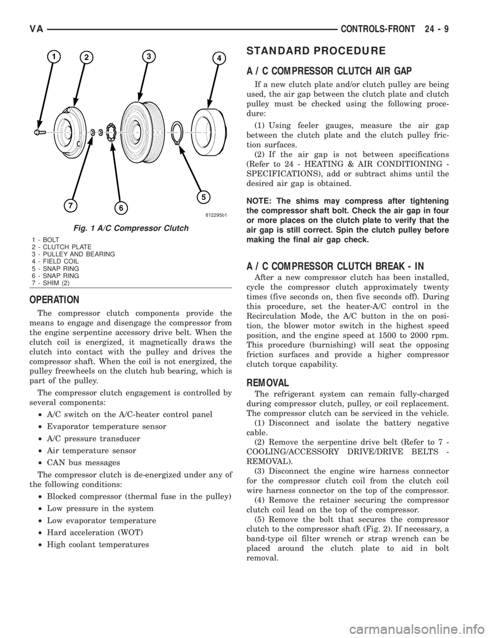
clutch to the compressor shaft (Fig. 2). If necessary, a
band-type oil filter wrench or strap wrench can be
placed around the clutch plate to aid in bolt
removal.
Fig. 1 A/C Compressor Clutch
1 - BOLT
2 - CLUTCH PLATE
3 - PULLEY AND BEARING
4 - FIELD COIL
5 - SNAP RING
6 - SNAP RING
7 - SHIM (2)
VACONTROLS-FRONT 24 - 9
Page 2068 of 2305
rear A/C compressor operation when the rear dis-
charge line pressure approaches high levels, and also
reduces electrical surging from rear A/C clutch
engagement.
The rear A/C high pressure switch controls rear
A/C condenser cooling fan operation by monitoring
the rear discharge line pressure. When the rear dis-
charge pressure rises above approximately 1900 to
2200 kPa (280 to 320 psi) the rear A/C condenser
cooling fan will turn on. The rear condenser cooling
fan will turn off when the rear discharge pressure
drops to approximately 1600 kPa (235 psi).
The rear A/C high pressure switch contacts open
when the rear discharge line pressure rises above
approximately 3100 to 3375 kPa (450 to 490 psi). The
rear A/C high pressure switch contacts close when
the rear discharge line pressure drops to approxi-
mately 1860 to 2275 kPa (270 to 330 psi).
The rear A/C high pressure switch is factory-cali-
brated and cannot be adjusted or repaired and, if
faulty or damaged, it must be replaced. Refer to the
appropriate wiring information for complete HVAC
wiring diagrams.
REMOVAL
WARNING: Refer to the applicable warnings and
cautions for this system before performing the fol-
lowing operation (Refer to 24 - HEATING & AIR
CONDITIONING/PLUMBING - WARNINGS) and (Refer
to 24 - HEATING & AIR CONDITIONING/PLUMBING -
CAUTIONS). Failure to follow the warnings and cau-
tions could result in possible personal injury or
death.
(1) Disconnect and isolate the negative battery
cable.
(2) Remove the air filter from the rear A/C evapo-
rator housing (Refer to 24 - HEATING & AIR CON-
DITIONING/DISTRIBUTION - REAR/AIR FILTER -
REMOVAL).
(3) Recover the refrigerant from the rear refriger-
ant system (Refer to 24 - HEATING & AIR CONDI-
TIONING/PLUMBING - STANDARD PROCEDURE -
REFRIGERANT RECOVERY).
(4) Remove the cover from the rear A/C condenser
housing (Refer to 24 - HEATING & AIR CONDI-
TIONING/DISTRIBUTION - REAR/A/C CON-
DENSER COVER - REMOVAL).
(5) Disconnect the wire harness connector from the
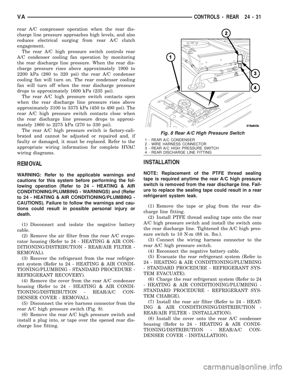
rear A/C high pressure switch (Fig. 8).
(6) Remove the rear A/C high pressure switch and
install a plug into, or tape over the opened rear dis-
charge line fitting.
INSTALLATION
NOTE: Replacement of the PTFE thread sealing
tape is required anytime the rear A/C high pressure
switch is removed from the rear discharge line. Fail-
ure to replace the sealing tape could result in a rear
refrigerant system leak.
(1) Remove the tape or plug from the rear dis-
charge line fitting.
(2) Install PTFE thread sealing tape onto the rear
A/C high pressure switch and install the switch onto
the rear discharge line. Tightened the A/C high pres-
sure switch to 10 N´m (88 in. lbs.).
(3) Connect the wiring harness connector to the
rear A/C high pressure switch.
(4) Reconnect the negative battery cable.
(5) Evacuate the rear refrigerant system (Refer to
24 - HEATING & AIR CONDITIONING/PLUMBING
- STANDARD PROCEDURE - REFRIGERANT SYS-
TEM EVACUATE).
(6) Charge the rear refrigerant system (Refer to 24
- HEATING & AIR CONDITIONING/PLUMBING -
STANDARD PROCEDURE - REFRIGERANT SYS-
TEM CHARGE).
(7) Install the rear air filter (Refer to 24 - HEAT-
ING & AIR CONDITIONING/DISTRIBUTION -
REAR/AIR FILTER - INSTALLATION).
(8) Install the cover onto the rear A/C condenser
housing (Refer to 24 - HEATING & AIR CONDI-
TIONING/DISTRIBUTION - REAR/A/C CON-
DENSER COVER - INSTALLATION).
Fig. 8 Rear A/C High Pressure Switch
1 - REAR A/C CONDENSER
2 - WIRE HARNESS CONNECTOR
3 - REAR A/C HIGH PRESSURE SWITCH
4 - REAR DISCHARGE LINE FITTING
VACONTROLS - REAR 24 - 31