2006 MERCEDES-BENZ SPRINTER engine
[x] Cancel search: enginePage 658 of 2305

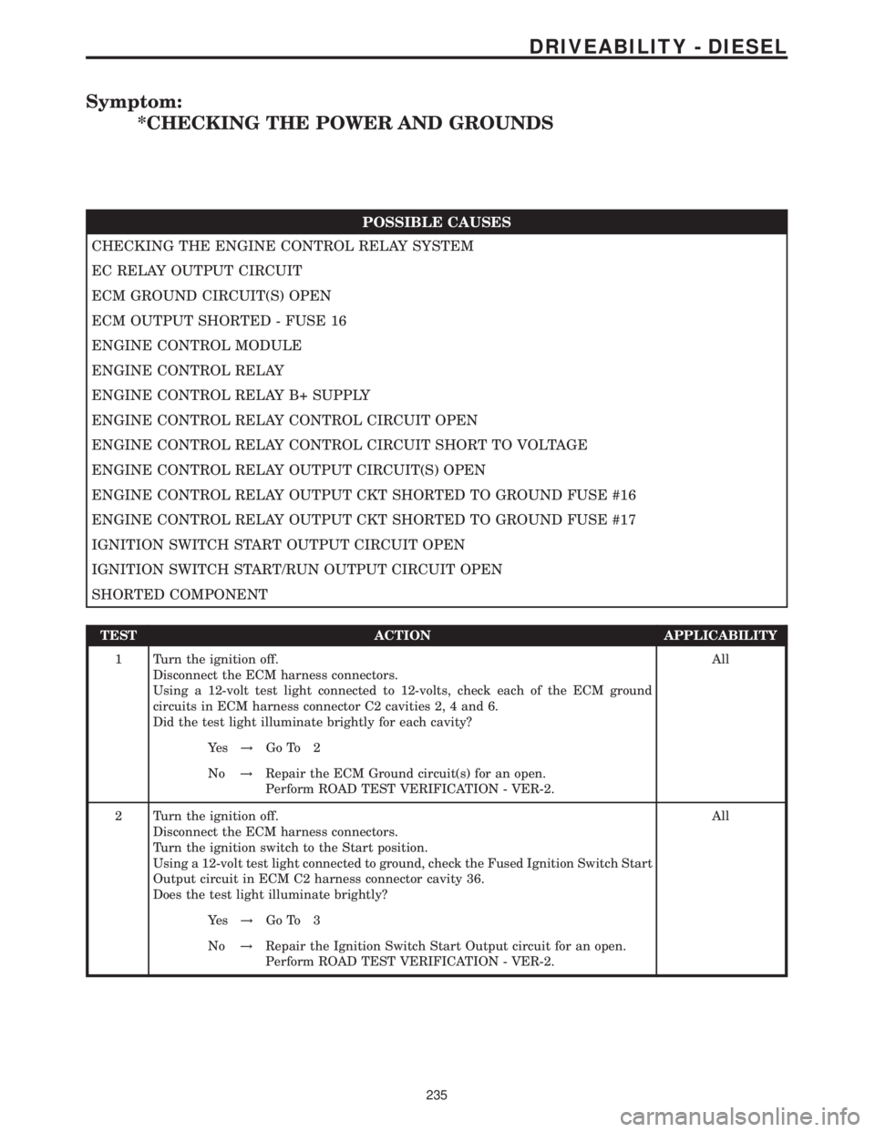
Symptom:
*CHECKING THE POWER AND GROUNDS
POSSIBLE CAUSES
CHECKING THE ENGINE CONTROL RELAY SYSTEM
EC RELAY OUTPUT CIRCUIT
ECM GROUND CIRCUIT(S) OPEN
ECM OUTPUT SHORTED - FUSE 16
ENGINE CONTROL MODULE
ENGINE CONTROL RELAY
ENGINE CONTROL RELAY B+ SUPPLY
ENGINE CONTROL RELAY CONTROL CIRCUIT OPEN
ENGINE CONTROL RELAY CONTROL CIRCUIT SHORT TO VOLTAGE
ENGINE CONTROL RELAY OUTPUT CIRCUIT(S) OPEN
ENGINE CONTROL RELAY OUTPUT CKT SHORTED TO GROUND FUSE #16
ENGINE CONTROL RELAY OUTPUT CKT SHORTED TO GROUND FUSE #17
IGNITION SWITCH START OUTPUT CIRCUIT OPEN
IGNITION SWITCH START/RUN OUTPUT CIRCUIT OPEN
SHORTED COMPONENT
TEST ACTION APPLICABILITY
1 Turn the ignition off.
Disconnect the ECM harness connectors.
Using a 12-volt test light connected to 12-volts, check each of the ECM ground
circuits in ECM harness connector C2 cavities 2, 4 and 6.
Did the test light illuminate brightly for each cavity?All
Ye s!Go To 2
No!Repair the ECM Ground circuit(s) for an open.
Perform ROAD TEST VERIFICATION - VER-2.
2 Turn the ignition off.
Disconnect the ECM harness connectors.
Turn the ignition switch to the Start position.
Using a 12-volt test light connected to ground, check the Fused Ignition Switch Start
Output circuit in ECM C2 harness connector cavity 36.
Does the test light illuminate brightly?All
Ye s!Go To 3
No!Repair the Ignition Switch Start Output circuit for an open.
Perform ROAD TEST VERIFICATION - VER-2.
235
DRIVEABILITY - DIESEL
Page 659 of 2305

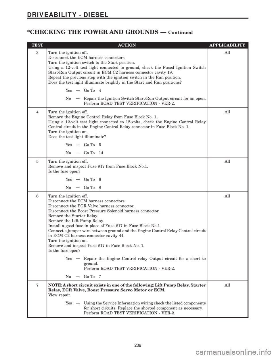
TEST ACTION APPLICABILITY
3 Turn the ignition off.
Disconnect the ECM harness connectors.
Turn the ignition switch to the Start position.
Using a 12-volt test light connected to ground, check the Fused Ignition Switch
Start/Run Output circuit in ECM C2 harness connector cavity 19.
Repeat the previous step with the ignition switch in the Run position.
Does the test light illuminate brightly in the Start and Run positions?All
Ye s!Go To 4
No!Repair the Ignition Switch Start/Run Output circuit for an open.
Perform ROAD TEST VERIFICATION - VER-2.
4 Turn the ignition off.
Remove the Engine Control Relay from Fuse Block No. 1.
Using a 12-volt test light connected to 12-volts, check the Engine Control Relay
Control circuit in the Engine Control Relay connector in Fuse Block No. 1.
Turn the ignition on.
Does the test light illuminate?All
Ye s!Go To 5
No!Go To 14
5 Turn the ignition off.
Remove and inspect Fuse #17 from Fuse Block No.1.
Is the fuse open?All
Ye s!Go To 6
No!Go To 8
6 Turn the ignition off.
Disconnect the ECM harness connectors.
Disconnect the EGR Valve harness connector.
Disconnect the Boost Pressure Solenoid harness connector.
Remove the Starter Relay.
Remove the Lift Pump Relay.
Install a good fuse in place of Fuse #17 in Fuse Block No.1
Connect a jumper wire between ground and the Engine Control Relay Control circuit
in ECM C2 harness connector cavity 44.
Turn the ignition on.
Remove and inspect Fuse #17 in Fuse Block No. 1.
Is the fuse open?All
Ye s!Repair the Engine Control relay Output circuit for a short to
ground.
Perform ROAD TEST VERIFICATION - VER-2.
No!Go To 7
7NOTE: A short circuit exists in one of the following: Lift Pump Relay, Starter
Relay, EGR Valve, Boost Pressure Servo Motor or ECM.
View repair.All
Ye s!Using the Service Information wiring check the listed components
for short circuits. Replace the shorted component as necessary.
Perform ROAD TEST VERIFICATION - VER-2.
236
DRIVEABILITY - DIESEL
*CHECKING THE POWER AND GROUNDS ÐContinued
Page 660 of 2305

TEST ACTION APPLICABILITY
8 Turn the ignition off.
Remove and inspect Fuse #16 from Fuse Block No.1
Is the fuse open?All
Ye s!Go To 9
No!Go To 11
9 Turn the ignition off.
Disconnect the ECM harness connectors.
Install a good fuse in place of Fuse #16 in Fuse Block No.1
Connect a jumper wire between ground and the Engine Control Relay Control circuit
in ECM C2 harness connector cavity 44.
Remove and inspect Fuse #16 from Fuse Block No.1.
Is the fuse open?All
Ye s!Repair the Engine Control Relay Output circuit for a short to
ground.
Perform ROAD TEST VERIFICATION - VER-2.
No!Go To 10
10 The Fuel Injectors, Crankcase Heater, Water In Fuel Sensor and related circuits can
cause Fuse #16 in Fuse Block No.1 to open. Use the Service Information Wiring
Diagrams and check these circuits/components for shorted circuits.
Were any problems found.All
Ye s!Repair or replace shorted circuit/component as necessary.
Perform ROAD TEST VERIFICATION - VER-2.
No!Replace and program the ECM in accordance with the Service
Information.
Perform ROAD TEST VERIFICATION - VER-2.
11 Turn the ignition off.
Disconnect the ECM harness connectors.
Connect a jumper wire between ground and the Engine Control Relay Control circuit
in ECM C2 harness connector cavity 44.
Turn the ignition on.
Using a 12-volt test light connected to ground, check the Fused Engine Control Relay
Output circuits at the ECM C2 harness connector cavities 1, 3 and 5.
Choose the appropriate result.All
Test light is on for all circuits.
Test Complete.
Test light is on for 1 or 2 circuits
Repair the Engine Control Relay Output circuit(s) for an open.
Perform ROAD TEST VERIFICATION - VER-2.
Light off for all circuits.
Go To 12
237
DRIVEABILITY - DIESEL
*CHECKING THE POWER AND GROUNDS ÐContinued
Page 661 of 2305

TEST ACTION APPLICABILITY
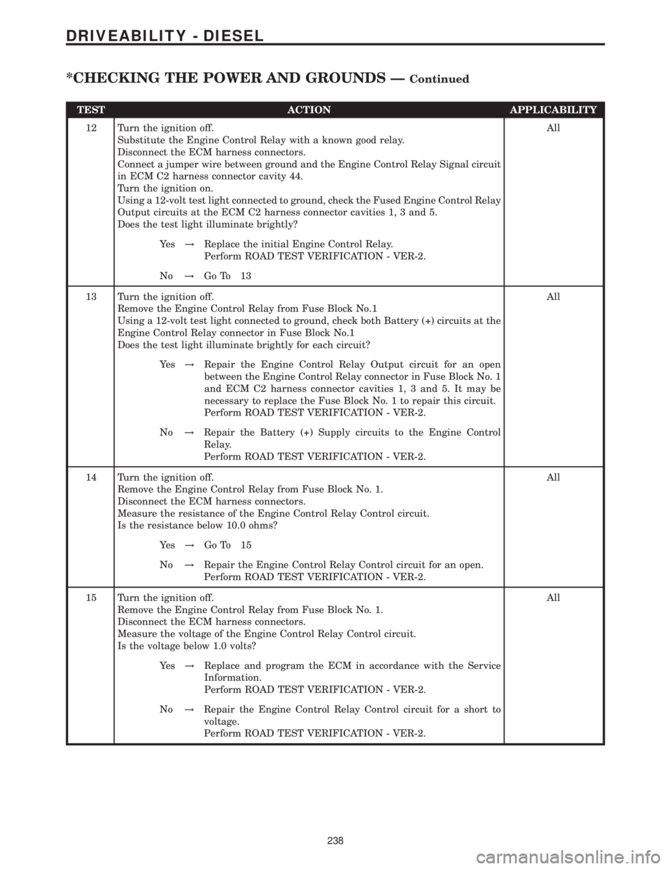
12 Turn the ignition off.
Substitute the Engine Control Relay with a known good relay.
Disconnect the ECM harness connectors.
Connect a jumper wire between ground and the Engine Control Relay Signal circuit
in ECM C2 harness connector cavity 44.
Turn the ignition on.
Using a 12-volt test light connected to ground, check the Fused Engine Control Relay
Output circuits at the ECM C2 harness connector cavities 1, 3 and 5.
Does the test light illuminate brightly?All
Ye s!Replace the initial Engine Control Relay.
Perform ROAD TEST VERIFICATION - VER-2.
No!Go To 13
13 Turn the ignition off.
Remove the Engine Control Relay from Fuse Block No.1
Using a 12-volt test light connected to ground, check both Battery (+) circuits at the
Engine Control Relay connector in Fuse Block No.1
Does the test light illuminate brightly for each circuit?All
Ye s!Repair the Engine Control Relay Output circuit for an open
between the Engine Control Relay connector in Fuse Block No. 1
and ECM C2 harness connector cavities 1, 3 and 5. It may be
necessary to replace the Fuse Block No. 1 to repair this circuit.
Perform ROAD TEST VERIFICATION - VER-2.
No!Repair the Battery (+) Supply circuits to the Engine Control
Relay.
Perform ROAD TEST VERIFICATION - VER-2.
14 Turn the ignition off.
Remove the Engine Control Relay from Fuse Block No. 1.
Disconnect the ECM harness connectors.
Measure the resistance of the Engine Control Relay Control circuit.
Is the resistance below 10.0 ohms?All
Ye s!Go To 15
No!Repair the Engine Control Relay Control circuit for an open.
Perform ROAD TEST VERIFICATION - VER-2.
15 Turn the ignition off.
Remove the Engine Control Relay from Fuse Block No. 1.
Disconnect the ECM harness connectors.
Measure the voltage of the Engine Control Relay Control circuit.
Is the voltage below 1.0 volts?All
Ye s!Replace and program the ECM in accordance with the Service
Information.
Perform ROAD TEST VERIFICATION - VER-2.
No!Repair the Engine Control Relay Control circuit for a short to
voltage.
Perform ROAD TEST VERIFICATION - VER-2.
238
DRIVEABILITY - DIESEL
*CHECKING THE POWER AND GROUNDS ÐContinued
Page 662 of 2305

Symptom:
*ENGINE CRANKS BUT WILL NOT START
POSSIBLE CAUSES
CAMSHAFT POSITION SENSOR SIGNAL PROBLEM
CRANKSHAFT POSITION SENSOR SIGNAL PROBLEM
ECM CODES PRESENT
ECT SENSOR
ENGINE CONTROL MODULE
ENGINE DRIVE GEAR/SPROCKET
FUEL SUPPLY CONTAMINATION
FUEL SYSTEM PRESSURE MECHANICAL
FUEL SYSTEM RESTRICTION
GLOW PLUGS
SKIM CODES PRESENT
TEST ACTION APPLICABILITY
1NOTE: The ECM must have proper power and ground connections for the
following tests to be valid. Refer to Checking the ECM Power and Grounds
in the symptom list.
NOTE: A no-start condition may occur if the Fuel Temperature Sensor is
shorted or if the Fuel Temperature Sensor Signal circuit is shorted to
ground or shorted to Sensor Ground.
Turn the ignition on.
With the DRBIIIt, read the ECM DTCs.
Does the DRBIIItdisplay any ECM DTCs?All
Ye s!Refer to symptom list for problems related to ECM DTC.
Perform NO START VERIFICATION - VER-1.
No!Go To 2
2 Turn the ignition on.
With the DRBIIIt, read the SKREEM DTCs.
Does the DRBIIItdisplay any SKREEM DTCs?All
Ye s!Refer to symptom list for problems related to SKIM DTC.
Perform NO START VERIFICATION - VER-1.
No!Go To 3
3 Using a temperature probe, check the vehicle temperature near the ECT Sensor.
Turn the ignition on.
With the DRBIIItin Sensors, read the ECT Sensor temperature.
Compare the temperature probe reading with the DRBIIItreading.
Are the two readings within 10ÉC of each other?All
Ye s!Go To 4
No!Repair as necessary.
Perform NO START VERIFICATION - VER-1.
239
DRIVEABILITY - DIESEL
Page 663 of 2305

TEST ACTION APPLICABILITY
4NOTE: Prior to performing this test, be sure to check the Glow Plug Relay
operation. Refer to CHECKING GLOW PLUG OPERATION for the related
symptom(s).
Refer to the Service Information and check the Glow Plugs for proper operation.
Are the Glow Plugs operating properly?All
Ye s!Go To 5
No!Repair as necessary.
Perform NO START VERIFICATION - VER-1.
5 Inspect the fuel system lines for restrictions, leaks or other problems.
NOTE: Refer to the Service Information to ensure that the fuel system is
properly primed. An unprimed system or excessive air in the supply system
will cause a no-start condition.
Is there any evidence of problems?All
Ye s!Repair as necessary.
Perform NO START VERIFICATION - VER-1.
No!Go To 6
6 Refer to the Service Information and perform the fuel pressure test.
Is the fuel pressure within specification?All
Ye s!Go To 7
No!Repair as necessary.
Perform NO START VERIFICATION - VER-1.
7 Inspect the fuel supply for contamination.
Is the fuel contaminated?All
Ye s!Refer to the Service Information to remove and replace fuel
throughout the fuel system.
Perform NO START VERIFICATION - VER-1.
No!Go To 8
8 Turn the ignition off.
Using the DRBIIItlab scope, backprobe the CMP Sensor Signal circuit at the ECM
harness connector.
Start the engine, if the engine will not start, crank the engine for several seconds
while monitoring the DRBIIIt.
NOTE: Refer to Charts and Graphs to view a correct CMP Sensor signal.
Does the DRBIIItdisplay a steady clean CMP Signal pattern?All
Ye s!Go To 9
No!Perform Test for DTC P2043-Camshaft Position Sensor Circuit
Static Plausibility.
Perform NO START VERIFICATION - VER-1.
240
DRIVEABILITY - DIESEL
*ENGINE CRANKS BUT WILL NOT START ÐContinued
Page 664 of 2305

TEST ACTION APPLICABILITY
9 Turn the ignition off.
Using the DRBIIItlab scope, backprobe both of the CKP Sensor Signal circuits at the
ECM harness connector.
NOTE: Refer to Charts and Graphs to view a correct CKP Sensor signal.
Start the engine, if the engine will not start, crank the engine for several seconds
while monitoring the DRBIIIt.
Does the DRBIIItdisplay a steady clean CKP Signal pattern for each circuit?All
Ye s!Go To 10
No!Perform Test for DTC P2045-Crankshaft Position Sensor Circuit
Dynamic Plausibility.
Perform NO START VERIFICATION - VER-1.
10 Refer to the Service Information to ensure the Engine Drive Gears/Sprocket are
installed correctly and the camshaft and crankshaft gears are timed correctly.
Were any problems found?All
Ye s!Repair as necessary.
Perform NO START VERIFICATION - VER-1.
No!Replace and program the Engine Control Module in accordance
with the Service Information.
Perform NO START VERIFICATION - VER-1.
241
DRIVEABILITY - DIESEL
*ENGINE CRANKS BUT WILL NOT START ÐContinued
Page 665 of 2305

Symptom:
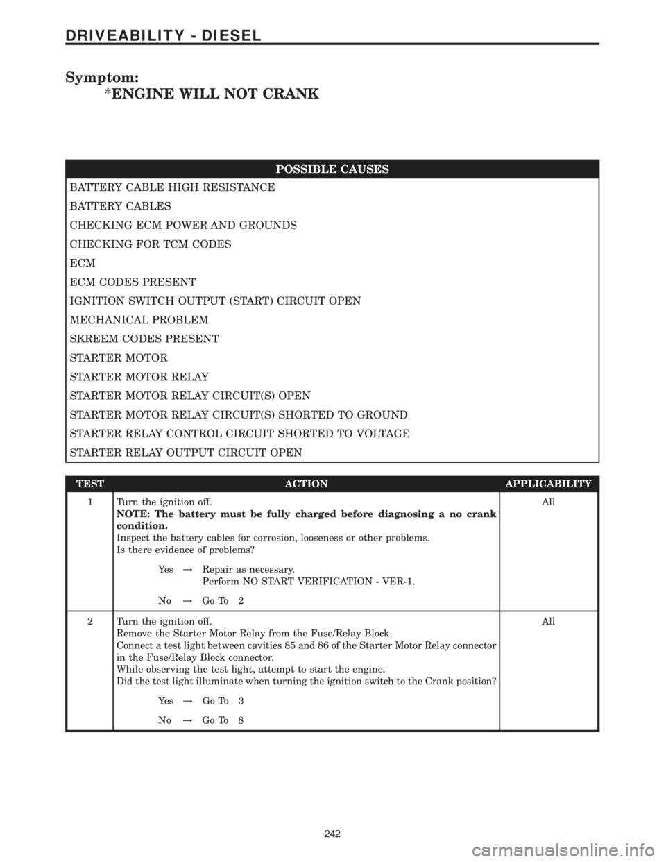
*ENGINE WILL NOT CRANK
POSSIBLE CAUSES
BATTERY CABLE HIGH RESISTANCE
BATTERY CABLES
CHECKING ECM POWER AND GROUNDS
CHECKING FOR TCM CODES
ECM
ECM CODES PRESENT
IGNITION SWITCH OUTPUT (START) CIRCUIT OPEN
MECHANICAL PROBLEM
SKREEM CODES PRESENT
STARTER MOTOR
STARTER MOTOR RELAY
STARTER MOTOR RELAY CIRCUIT(S) OPEN
STARTER MOTOR RELAY CIRCUIT(S) SHORTED TO GROUND
STARTER RELAY CONTROL CIRCUIT SHORTED TO VOLTAGE
STARTER RELAY OUTPUT CIRCUIT OPEN
TEST ACTION APPLICABILITY
1 Turn the ignition off.
NOTE: The battery must be fully charged before diagnosing a no crank
condition.
Inspect the battery cables for corrosion, looseness or other problems.
Is there evidence of problems?All
Ye s!Repair as necessary.
Perform NO START VERIFICATION - VER-1.
No!Go To 2
2 Turn the ignition off.
Remove the Starter Motor Relay from the Fuse/Relay Block.
Connect a test light between cavities 85 and 86 of the Starter Motor Relay connector
in the Fuse/Relay Block connector.
While observing the test light, attempt to start the engine.
Did the test light illuminate when turning the ignition switch to the Crank position?All
Ye s!Go To 3
No!Go To 8
242
DRIVEABILITY - DIESEL