2006 MERCEDES-BENZ SPRINTER turn signal bulb
[x] Cancel search: turn signal bulbPage 1000 of 2305

Communication Interface (SCI) data bus line for sup-
plemental restraint system programming or diagno-
sis and testing through the 16-way Data Link
Connector (DLC) located on the dash panel below the
driver side end of the instrument panel. A hard wired
output from the ACM is used for control of the airbag
indicator in the ElectroMechanical Instrument Clus-
ter (EMIC). (Refer to 8 - ELECTRICAL/INSTRU-
MENT CLUSTER/AIRBAG INDICATOR -
OPERATION).
The ACM microprocessor continuously monitors all
of the supplemental restraint system electrical cir-
cuits to determine the system readiness. If the ACM
detects a monitored system fault, it sets an appropri-
ate Diagnostic Trouble Code (DTC) and sends an out-
put to the EMIC to turn on the airbag indicator. The
ACM illuminates the indicator for about four seconds
each time the ignition switch is turned to the On
position as a bulb test. If the indicator remains illu-
minated for about ten seconds after the ignition
switch is turned to the On position, the ACM has
detected a non-critical fault that poses no danger to
the vehicle occupants. If the airbag indicator illumi-
nates solid (not flashing) while driving or stays on
longer than ten seconds following the bulb test, the
ACM has detected a critical fault that may cause the
airbags not to deploy when required or to deploy
when not required. An active fault only remains for
the duration of the fault, or in some cases, for the
duration of the current ignition switch cycle, while a
stored fault causes a DTC to be stored in memory by
the ACM.
The ACM receives battery current through a fused
ignition switch output circuit. The ACM receives
ground through a ground circuit and take out of the
vehicle wire harness. This take out has an eyelet ter-
minal connector secured by a nut to a ground stud on
the floor panel directly below the ACM within the
driver side seat riser. A case ground is also provided
for the ACM through a ground circuit and eyelet ter-
minal connector secured under the left rear ACM
mounting screw. These connections allow the ACM to
be operational whenever the ignition switch is in the
On position.
The ACM also contains an energy-storage capaci-
tor. When the ignition switch is in the On position,
this capacitor is continually being charged with
enough electrical energy to deploy the supplemental
restraint components for up to one second following a
battery disconnect or failure. The purpose of the
capacitor is to provide backup supplemental restraint
system protection in case there is a loss of battery
current supply to the ACM during an impact.
Two sensors are contained within the ACM, an
electronic impact sensor and a safing sensor. These
electronic sensors are accelerometers that sense the
rate of vehicle deceleration, which provide verifica-
tion of the direction and severity of an impact. Onmodels equipped with optional side curtain airbags,
the ACM also monitors inputs from two remote side
impact sensors located within the left and right front
door step wells to control deployment of the side cur-
tain airbag units.
The safing sensor is an electronic accelerometer
sensor within the ACM that provides an additional
logic input to the ACM microprocessor. The safing
sensor is used to verify the need for a supplemental
restraint deployment by detecting impact energy of a
lesser magnitude than that of the primary electronic
impact sensors, and must exceed a safing threshold
in order for the airbags to deploy. Vehicles equipped
with optional side curtain airbags feature a second
safing sensor within the ACM to provide confirma-
tion to the ACM microprocessor of side impact forces.
This second safing sensor is a bi-directional unit that
detects impact forces from either side of the vehicle.
Pre-programmed decision algorithms in the ACM
microprocessor determine when the deceleration rate
as signaled by the impact sensors and the safing sen-
sors indicate an impact that is severe enough to
require supplemental restraint system protection.
When the programmed conditions are met, the ACM
sends the proper electrical signals to deploy the front
airbags and seat belt tensioners and, if the vehicle is
so equipped, either side curtain airbag unit.
The ACM also provides a hard wired electrical
crash signal output following a supplemental
restraint deployment event. This output is used to
signal other electronic modules in the vehicle to pro-
vide their enhanced accident response features,
which include automatically disabling the engine
from running and unlocking all of the doors. How-
ever, these responses are each dependent upon the
circuits, components, and modules controlling these
features remaining intact from collateral damage
incurred during the vehicle impact.
A single ACM is used for all variations of the sup-
plemental restraint system available in this vehicle.
This ACM is programmable and in order to function
properly it must be programmed for the correct vehi-
cle supplemental restraint system equipment using
an initialization procedure. The initialization proce-
dure requires the use of a diagnostic scan tool. Refer
to the appropriate diagnostic information. The hard
wired inputs and outputs for the ACM may be diag-
nosed and tested using conventional diagnostic tools
and procedures. However, conventional diagnostic
methods will not prove conclusive in the diagnosis of
the ACM or the supplemental restraint system. The
most reliable, efficient, and accurate means to diag-
nose the ACM or the supplemental restraint system
requires the use of a diagnostic scan tool. Refer to
the appropriate diagnostic information.
VARESTRAINTS 8O - 9
Page 2159 of 2305
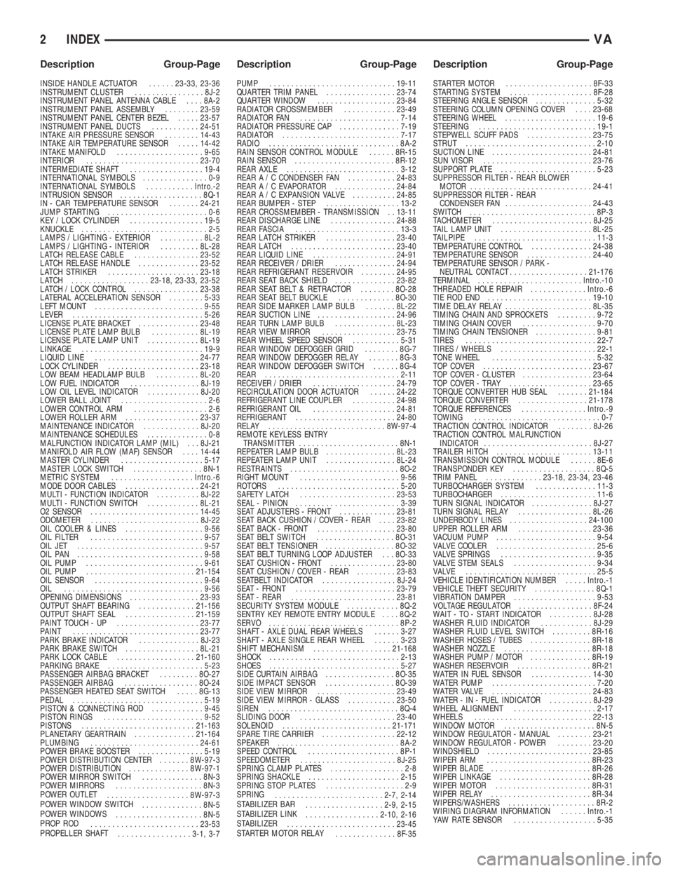
INSIDE HANDLE ACTUATOR......23-33, 23-36
INSTRUMENT CLUSTER................8J-2
INSTRUMENT PANEL ANTENNA CABLE....8A-2
INSTRUMENT PANEL ASSEMBLY........23-59
INSTRUMENT PANEL CENTER BEZEL.....23-57
INSTRUMENT PANEL DUCTS...........24-51
INTAKE AIR PRESSURE SENSOR........14-43
INTAKE AIR TEMPERATURE SENSOR.....14-42
INTAKE MANIFOLD....................9-65
INTERIOR..........................23-70
INTERMEDIATE SHAFT.................19-4
INTERNATIONAL SYMBOLS...............0-9
INTERNATIONAL SYMBOLS...........Intro.-2
INTRUSION SENSOR...................8Q-1
IN - CAR TEMPERATURE SENSOR.......24-21
JUMP STARTING.......................0-6
KEY / LOCK CYLINDER.................19-5
KNUCKLE.............................2-5
LAMPS / LIGHTING - EXTERIOR..........8L-2
LAMPS / LIGHTING - INTERIOR.........8L-28
LATCH RELEASE CABLE...............23-52
LATCH RELEASE HANDLE..............23-52
LATCH STRIKER.....................23-18
LATCH ..................23-18, 23-33, 23-52
LATCH / LOCK CONTROL...............23-38
LATERAL ACCELERATION SENSOR........5-33
LEFT MOUNT.........................9-55
LEVER..............................5-26
LICENSE PLATE BRACKET..............23-48
LICENSE PLATE LAMP BULB...........8L-19
LICENSE PLATE LAMP UNIT............8L-19
LINKAGE............................19-9
LIQUID LINE........................24-77
LOCK CYLINDER.....................23-18
LOW BEAM HEADLAMP BULB..........8L-20
LOW FUEL INDICATOR................8J-19
LOW OIL LEVEL INDICATOR............8J-20
LOWER BALL JOINT....................2-6
LOWER CONTROL ARM.................2-6
LOWER ROLLER ARM.................23-37
MAINTENANCE INDICATOR.............8J-20
MAINTENANCE SCHEDULES..............0-8
MALFUNCTION INDICATOR LAMP (MIL) . . . 8J-21
MANIFOLD AIR FLOW (MAF) SENSOR....14-44
MASTER CYLINDER...................5-17
MASTER LOCK SWITCH................8N-1
METRIC SYSTEM...................Intro.-6
MODE DOOR CABLES.................24-21
MULTI - FUNCTION INDICATOR..........8J-22
MULTI - FUNCTION SWITCH............8L-21
O2 SENSOR.........................14-45
ODOMETER.........................8J-22
OIL COOLER & LINES..................9-56
OIL FILTER ..........................9-57
OIL JET .............................9-57
OIL PAN .............................9-58
OIL PUMP...........................9-61
OIL PUMP.........................21-154
OIL SENSOR.........................9-64
OIL ................................9-56
OPENING DIMENSIONS................23-93
OUTPUT SHAFT BEARING.............21-156
OUTPUT SHAFT SEAL................21-159
PAINT TOUCH - UP...................23-77
PAINT.............................23-77
PARK BRAKE INDICATOR..............8J-23
PARK BRAKE SWITCH.................8L-21
PARK LOCK CABLE..................21-160
PARKING BRAKE......................5-23
PASSENGER AIRBAG BRACKET.........8O-27
PASSENGER AIRBAG.................8O-24
PASSENGER HEATED SEAT SWITCH.....8G-13
PEDAL..............................5-19
PISTON & CONNECTING ROD............9-45
PISTON RINGS.......................9-52
PISTONS..........................21-163
PLANETARY GEARTRAIN..............21-164
PLUMBING.........................24-61
POWER BRAKE BOOSTER...............5-19
POWER DISTRIBUTION CENTER.......8W-97-3
POWER DISTRIBUTION..............8W-97-1
POWER MIRROR SWITCH..............8N-3
POWER MIRRORS....................8N-3
POWER OUTLET
...................8W-97-3
POWER WINDOW SWITCH
..............8N-5
POWER WINDOWS
....................8N-5
PROP ROD
.........................23-53
PROPELLER SHAFT
.................3-1, 3-7PUMP.............................19-11
QUARTER TRIM PANEL................23-74
QUARTER WINDOW..................23-84
RADIATOR CROSSMEMBER............23-49
RADIATOR FAN.......................7-14
RADIATOR PRESSURE CAP..............7-19
RADIATOR...........................7-17
RADIO..............................8A-2
RAIN SENSOR CONTROL MODULE......8R-15
RAIN SENSOR.......................8R-12
REAR AXLE..........................3-12
REAR A / C CONDENSER FAN...........24-83
REAR A / C EVAPORATOR..............24-84
REAR A / C EXPANSION VALVE..........24-85
REAR BUMPER - STEP.................13-2
REAR CROSSMEMBER - TRANSMISSION . . 13-11
REAR DISCHARGE LINE...............24-88
REAR FASCIA........................13-3
REAR LATCH STRIKER................23-40
REAR LATCH........................23-40
REAR LIQUID LINE...................24-91
REAR RECEIVER / DRIER..............24-94
REAR REFRIGERANT RESERVOIR........24-95
REAR SEAT BACK SHIELD..............23-82
REAR SEAT BELT & RETRACTOR........8O-28
REAR SEAT BELT BUCKLE.............8O-30
REAR SIDE MARKER LAMP BULB.......8L-22
REAR SUCTION LINE..................24-96
REAR TURN LAMP BULB..............8L-23
REAR VIEW MIRROR.................23-75
REAR WHEEL SPEED SENSOR...........5-31
REAR WINDOW DEFOGGER GRID........8G-7
REAR WINDOW DEFOGGER RELAY.......8G-3
REAR WINDOW DEFOGGER SWITCH......8G-4
REAR...............................2-11
RECEIVER / DRIER...................24-79
RECIRCULATION DOOR ACTUATOR......24-22
REFRIGERANT LINE COUPLER..........24-98
REFRIGERANT OIL...................24-81
REFRIGERANT.......................24-80
RELAY...........................8W-97-4
REMOTE KEYLESS ENTRY
TRANSMITTER.......................8N-1
REPEATER LAMP BULB................8L-23
REPEATER LAMP UNIT................8L-24
RESTRAINTS.........................8O-2
RIGHT MOUNT.......................9-56
ROTORS............................5-20
SAFETY LATCH......................23-53
SEAL - PINION........................3-39
SEAT ADJUSTERS - FRONT.............23-81
SEAT BACK CUSHION / COVER - REAR....23-82
SEAT BACK - FRONT..................23-80
SEAT BELT SWITCH..................8O-31
SEAT BELT TENSIONER................8O-32
SEAT BELT TURNING LOOP ADJUSTER . . . 8O-33
SEAT CUSHION - FRONT...............23-80
SEAT CUSHION / COVER - REAR.........23-83
SEATBELT INDICATOR.................8J-24
SEAT - FRONT.......................23-79
SEAT - REAR........................23-81
SECURITY SYSTEM MODULE............8Q-2
SENTRY KEY REMOTE ENTRY MODULE....8Q-2
SERVO..............................8P-2
SHAFT - AXLE DUAL REAR WHEELS......3-27
SHAFT - AXLE SINGLE REAR WHEEL......3-23
SHIFT MECHANISM..................21-168
SHOCK..............................2-13
SHOES..............................5-27
SIDE CURTAIN AIRBAG................8O-35
SIDE IMPACT SENSOR................8O-39
SIDE VIEW MIRROR..................23-49
SIDE VIEW MIRROR - GLASS...........23-50
SIREN..............................8Q-4
SLIDING DOOR......................23-40
SOLENOID.........................21-171
SPARE TIRE CARRIER.................22-12
SPEAKER............................8A-2
SPEED CONTROL.....................8P-1
SPEEDOMETER......................8J-25
SPRING CLAMP PLATES.................2-8
SPRING SHACKLE.....................2-15
SPRING STOP PLATES..................2-9
SPRING
.........................2-7, 2-14
STABILIZER BAR
..................2-9, 2-15
STABILIZER LINK
.................2-10, 2-16
STABILIZER
.........................23-45
STARTER MOTOR RELAY
..............8F-35STARTER MOTOR....................8F-33
STARTING SYSTEM...................8F-28
STEERING ANGLE SENSOR..............5-32
STEERING COLUMN OPENING COVER....23-68
STEERING WHEEL.....................19-6
STEERING...........................19-1
STEPWELL SCUFF PADS...............23-75
STRUT..............................2-10
SUCTION LINE.......................24-81
SUN VISOR.........................23-76
SUPPORT PLATE......................5-23
SUPPRESSOR FILTER - REAR BLOWER
MOTOR............................24-41
SUPPRESSOR FILTER - REAR
CONDENSER FAN....................24-43
SWITCH.............................8P-3
TACHOMETER.......................8J-25
TAIL LAMP UNIT.....................8L-25
TAILPIPE............................11-3
TEMPERATURE CONTROL..............24-38
TEMPERATURE SENSOR...............24-40
TEMPERATURE SENSOR / PARK -
NEUTRAL CONTACT..................21-176
TERMINAL........................Intro.-10
THREADED HOLE REPAIR.............Intro.-6
TIE ROD END ........................19-10
TIME DELAY RELAY....................8L-35
TIMING CHAIN AND SPROCKETS.........9-72
TIMING CHAIN COVER.................9-70
TIMING CHAIN TENSIONER..............9-81
TIRES..............................22-7
TIRES / WHEELS......................22-1
TONE WHEEL........................5-32
TOP COVER.........................23-67
TOP COVER - CLUSTER................23-64
TOP COVER - TRAY...................23-65
TORQUE CONVERTER HUB SEAL.......21-184
TORQUE CONVERTER................21-178
TORQUE REFERENCES...............Intro.-9
TOWING.............................0-7
TRACTION CONTROL INDICATOR........8J-26
TRACTION CONTROL MALFUNCTION
INDICATOR.........................8J-27
TRAILER HITCH......................13-11
TRANSMISSION CONTROL MODULE......8E-6
TRANSPONDER KEY...................8Q-5
TRIM PANEL.............23-18, 23-34, 23-46
TURBOCHARGER SYSTEM..............11-3
TURBOCHARGER......................11-6
TURN SIGNAL INDICATOR..............8J-27
TURN SIGNAL RELAY.................8L-26
UNDERBODY LINES..................24-100
UPPER ROLLER ARM.................23-36
VACUUM PUMP.......................9-54
VALVE COOLER.......................25-6
VALVE SPRINGS......................9-35
VALVE STEM SEALS...................9-34
VALVE ..............................25-5
VEHICLE IDENTIFICATION NUMBER.....Intro.-1
VEHICLE THEFT SECURITY..............8Q-1
VIBRATION DAMPER...................9-53
VOLTAGE REGULATOR.................8F-24
WAIT - TO - START INDICATOR..........8J-28
WASHER FLUID INDICATOR............8J-29
WASHER FLUID LEVEL SWITCH.........8R-16
WASHER HOSES / TUBES..............8R-18
WASHER NOZZLE....................8R-18
WASHER PUMP / MOTOR..............8R-19
WASHER RESERVOIR.................8R-21
WATER IN FUEL SENSOR..............14-30
WATER PUMP........................7-20
WATER VALVE .......................24-83
WATER - IN - FUEL INDICATOR..........8J-29
WHEEL ALIGNMENT...................2-17
WHEELS...........................22-13
WINDOW MOTOR.....................8N-5
WINDOW REGULATOR - MANUAL........23-21
WINDOW REGULATOR - POWER........23-20
WINDSHIELD........................23-85
WIPER ARM........................8R-23
WIPER BLADE.......................8R-26
WIPER LINKAGE.....................8R-28
WIPER MOTOR......................8R-31
WIPER RELAY.......................8R-34
WIPERS/WASHERS....................8R-2
WIRING DIAGRAM INFORMATION......Intro.-1
YAW RATE SENSOR...................5-35
2 INDEXVA
Description Group-Page Description Group-Page Description Group-Page