2006 MERCEDES-BENZ SPRINTER diagram
[x] Cancel search: diagramPage 71 of 2305
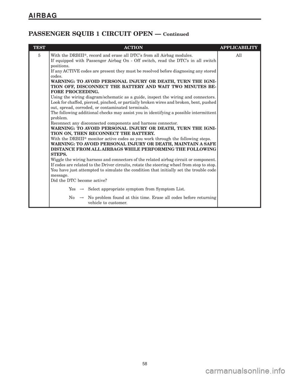
TEST ACTION APPLICABILITY
5 With the DRBIIIt, record and erase all DTC's from all Airbag modules.
If equipped with Passenger Airbag On - Off switch, read the DTC's in all switch
positions.
If any ACTIVE codes are present they must be resolved before diagnosing any stored
codes.
WARNING: TO AVOID PERSONAL INJURY OR DEATH, TURN THE IGNI-
TION OFF, DISCONNECT THE BATTERY AND WAIT TWO MINUTES BE-
FORE PROCEEDING.
Using the wiring diagram/schematic as a guide, inspect the wiring and connectors.
Look for chaffed, pierced, pinched, or partially broken wires and broken, bent, pushed
out, spread, corroded, or contaminated terminals.
The following additional checks may assist you in identifying a possible intermittent
problem.
Reconnect any disconnected components and harness connector.
WARNING: TO AVOID PERSONAL INJURY OR DEATH, TURN THE IGNI-
TION ON, THEN RECONNECT THE BATTERY.
With the DRBIIItmonitor active codes as you work through the following steps.
WARNING: TO AVOID PERSONAL INJURY OR DEATH, MAINTAIN A SAFE
DISTANCE FROM ALL AIRBAGS WHILE PERFORMING THE FOLLOWING
STEPS.
Wiggle the wiring harness and connectors of the related airbag circuit or component.
If codes are related to the Driver circuits, rotate the steering wheel from stop to stop.
You have just attempted to simulate the condition that initially set the trouble code
message.
Did the DTC become active?All
Ye s!Select appropriate symptom from Symptom List.
No!No problem found at this time. Erase all codes before returning
vehicle to customer.
58
AIRBAG
PASSENGER SQUIB 1 CIRCUIT OPEN ÐContinued
Page 74 of 2305
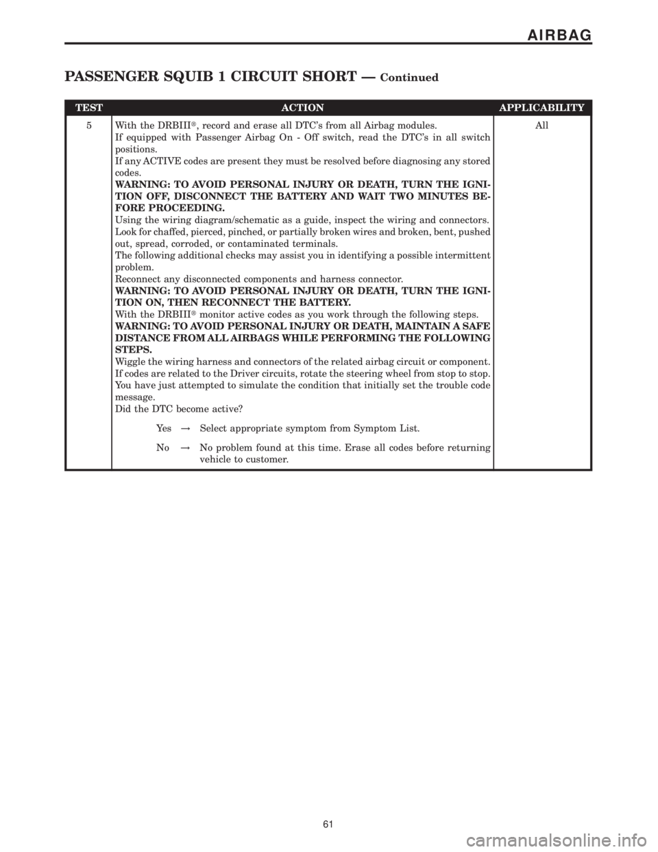
TEST ACTION APPLICABILITY
5 With the DRBIIIt, record and erase all DTC's from all Airbag modules.
If equipped with Passenger Airbag On - Off switch, read the DTC's in all switch
positions.
If any ACTIVE codes are present they must be resolved before diagnosing any stored
codes.
WARNING: TO AVOID PERSONAL INJURY OR DEATH, TURN THE IGNI-
TION OFF, DISCONNECT THE BATTERY AND WAIT TWO MINUTES BE-
FORE PROCEEDING.
Using the wiring diagram/schematic as a guide, inspect the wiring and connectors.
Look for chaffed, pierced, pinched, or partially broken wires and broken, bent, pushed
out, spread, corroded, or contaminated terminals.
The following additional checks may assist you in identifying a possible intermittent
problem.
Reconnect any disconnected components and harness connector.
WARNING: TO AVOID PERSONAL INJURY OR DEATH, TURN THE IGNI-
TION ON, THEN RECONNECT THE BATTERY.
With the DRBIIItmonitor active codes as you work through the following steps.
WARNING: TO AVOID PERSONAL INJURY OR DEATH, MAINTAIN A SAFE
DISTANCE FROM ALL AIRBAGS WHILE PERFORMING THE FOLLOWING
STEPS.
Wiggle the wiring harness and connectors of the related airbag circuit or component.
If codes are related to the Driver circuits, rotate the steering wheel from stop to stop.
You have just attempted to simulate the condition that initially set the trouble code
message.
Did the DTC become active?All
Ye s!Select appropriate symptom from Symptom List.
No!No problem found at this time. Erase all codes before returning
vehicle to customer.
61
AIRBAG
PASSENGER SQUIB 1 CIRCUIT SHORT ÐContinued
Page 77 of 2305
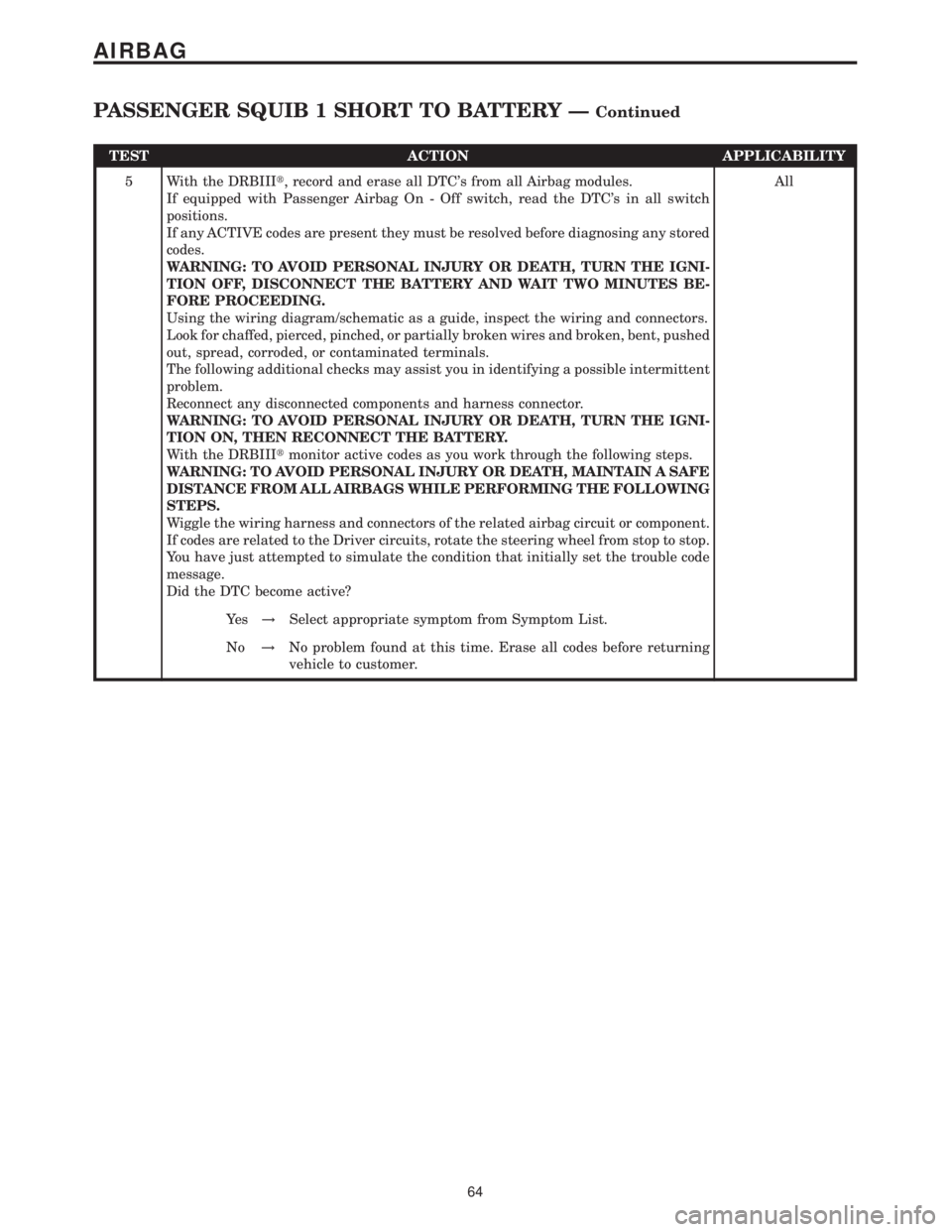
TEST ACTION APPLICABILITY
5 With the DRBIIIt, record and erase all DTC's from all Airbag modules.
If equipped with Passenger Airbag On - Off switch, read the DTC's in all switch
positions.
If any ACTIVE codes are present they must be resolved before diagnosing any stored
codes.
WARNING: TO AVOID PERSONAL INJURY OR DEATH, TURN THE IGNI-
TION OFF, DISCONNECT THE BATTERY AND WAIT TWO MINUTES BE-
FORE PROCEEDING.
Using the wiring diagram/schematic as a guide, inspect the wiring and connectors.
Look for chaffed, pierced, pinched, or partially broken wires and broken, bent, pushed
out, spread, corroded, or contaminated terminals.
The following additional checks may assist you in identifying a possible intermittent
problem.
Reconnect any disconnected components and harness connector.
WARNING: TO AVOID PERSONAL INJURY OR DEATH, TURN THE IGNI-
TION ON, THEN RECONNECT THE BATTERY.
With the DRBIIItmonitor active codes as you work through the following steps.
WARNING: TO AVOID PERSONAL INJURY OR DEATH, MAINTAIN A SAFE
DISTANCE FROM ALL AIRBAGS WHILE PERFORMING THE FOLLOWING
STEPS.
Wiggle the wiring harness and connectors of the related airbag circuit or component.
If codes are related to the Driver circuits, rotate the steering wheel from stop to stop.
You have just attempted to simulate the condition that initially set the trouble code
message.
Did the DTC become active?All
Ye s!Select appropriate symptom from Symptom List.
No!No problem found at this time. Erase all codes before returning
vehicle to customer.
64
AIRBAG
PASSENGER SQUIB 1 SHORT TO BATTERY ÐContinued
Page 80 of 2305
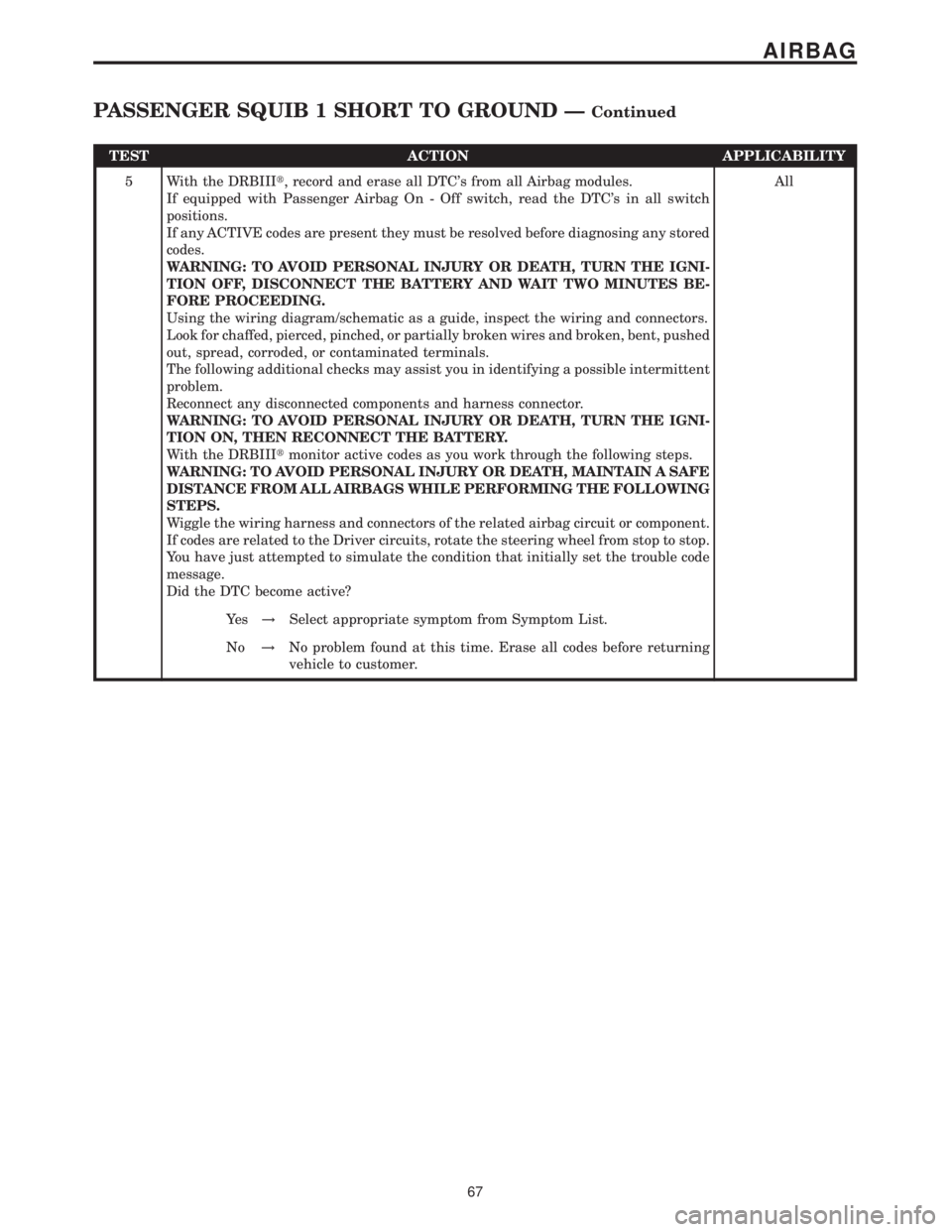
TEST ACTION APPLICABILITY
5 With the DRBIIIt, record and erase all DTC's from all Airbag modules.
If equipped with Passenger Airbag On - Off switch, read the DTC's in all switch
positions.
If any ACTIVE codes are present they must be resolved before diagnosing any stored
codes.
WARNING: TO AVOID PERSONAL INJURY OR DEATH, TURN THE IGNI-
TION OFF, DISCONNECT THE BATTERY AND WAIT TWO MINUTES BE-
FORE PROCEEDING.
Using the wiring diagram/schematic as a guide, inspect the wiring and connectors.
Look for chaffed, pierced, pinched, or partially broken wires and broken, bent, pushed
out, spread, corroded, or contaminated terminals.
The following additional checks may assist you in identifying a possible intermittent
problem.
Reconnect any disconnected components and harness connector.
WARNING: TO AVOID PERSONAL INJURY OR DEATH, TURN THE IGNI-
TION ON, THEN RECONNECT THE BATTERY.
With the DRBIIItmonitor active codes as you work through the following steps.
WARNING: TO AVOID PERSONAL INJURY OR DEATH, MAINTAIN A SAFE
DISTANCE FROM ALL AIRBAGS WHILE PERFORMING THE FOLLOWING
STEPS.
Wiggle the wiring harness and connectors of the related airbag circuit or component.
If codes are related to the Driver circuits, rotate the steering wheel from stop to stop.
You have just attempted to simulate the condition that initially set the trouble code
message.
Did the DTC become active?All
Ye s!Select appropriate symptom from Symptom List.
No!No problem found at this time. Erase all codes before returning
vehicle to customer.
67
AIRBAG
PASSENGER SQUIB 1 SHORT TO GROUND ÐContinued
Page 115 of 2305
Symptom:
*NO RESPONSE FROM AIRBAG CONTROL MODULE
POSSIBLE CAUSES
CHECK POWERS AND GROUNDS TO THE AIRBAG CONTROL MODULE
K-ACM CIRCUIT SHORTED TO GROUND
K-ACM CIRCUIT SHORTED TO VOLTAGE
K-ACM CIRCUIT OPEN
AIRBAG CONTROL MODULE
TEST ACTION APPLICABILITY
1WARNING: TURN THE IGNITION OFF, DISCONNECT THE BATTERY AND
WAIT TWO MINUTES BEFORE PROCEEDING. FAILURE TO DO SO MAY
RESULT IN PERSONAL INJURY OR DEATH.
Disconnect the Airbag Control Module harness connector.
Check each power and ground circuit to the module.
Were any problems found?All
Ye s!Refer to the wiring diagrams located in the service information to
help isolate an open or shorted condition. Repair as necessary.
Perform __AIRBAG VERIFICATION TEST - VER 1.
No!Go To 2
2WARNING: TURN THE IGNITION OFF, DISCONNECT THE BATTERY AND
WAIT TWO MINUTES BEFORE PROCEEDING. FAILURE TO DO SO MAY
RESULT IN PERSONAL INJURY OR DEATH.
Disconnect the ACM harness connector.
Disconnect the DRBIIItfrom the DLC.
Measure the resistance between ground and the K-ACM circuit.
Is the resistance below 5.0 ohms?All
Ye s!Repair the K-ACM circuit for a short to ground.
Perform __AIRBAG VERIFICATION TEST - VER 1.
No!Go To 3
3WARNING: TURN THE IGNITION OFF, DISCONNECT THE BATTERY AND
WAIT TWO MINUTES BEFORE PROCEEDING. FAILURE TO DO SO MAY
RESULT IN PERSONAL INJURY OR DEATH.
Disconnect the DRBIIItfrom the DLC.
Disconnect the ACM harness connector.
Turn the ignition on.
Using a 12-volt test light connected to ground, probe the K-ACM circuit.
NOTE: The test light must illuminate brightly. Compare the brightness to
that of a direct connection to the battery.
Does the test light illuminate brightly?All
Ye s!Repair the K-ACM circuit for a short to voltage.
Perform __AIRBAG VERIFICATION TEST - VER 1.
No!Go To 4
102
COMMUNICATION
Page 117 of 2305
Symptom:
*NO RESPONSE FROM AUTOMATIC TEMPERATURE CONTROL
POSSIBLE CAUSES
CHECK POWERS AND GROUNDS TO THE AUTOMATIC TEMPERATURE CONTROL
MODULE - INTERNAL SHORT TO GROUND
K-IC, ATC, HBM, CHM CIRCUIT SHORTED TO GROUND
MODULE - INTERNAL SHORT TO VOLTAGE
K-IC, ATC, HBM, CHM CIRCUIT SHORTED TO VOLTAGE
K-IC, ATC, HBM, CHM CIRCUIT OPEN
AUTOMATIC TEMPERATURE CONTROL
TEST ACTION APPLICABILITY
1 Turn the ignition off.
Disconnect the Automatic Temperature Control harness connectors.
Check each power and ground circuit to the module.
Were any problems found?All
Ye s!Refer to the wiring diagrams located in the service information to
help isolate an open or shorted condition. Repair as necessary.
Perform BODY VERIFICATION TEST - VER 1.
No!Go To 2
2 Turn the ignition off.
Disconnect the Automatic Temperature Control harness connectors.
Disconnect the DRBIIItfrom the DLC.
Measure the resistance between ground and the K-IC, ATC, HBM, CHM circuit.
Is the resistance below 5.0 ohms?All
Ye s!Go To 3
No!Go To 4
3 Turn the ignition off.
Disconnect the Automatic Temperature Control harness connectors.
Measure the resistance between ground and the K-IC, ATC, HBM, CHM circuit.
While monitoring the ohmmeter, disconnect each module (IC, HBM, CHM) one at a
time.
NOTE: The vehicle may not be equipped with all the above modules.
Is the resistance below 5.0 ohms with all the above modules disconnected?All
Ye s!Repair the K-IC, ATC, HBM, CHM circuit for a short to ground.
Perform BODY VERIFICATION TEST - VER 1.
No!Replace the Module, that when disconnected the short was
eliminated, in accordance with the service information.
Perform BODY VERIFICATION TEST - VER 1.
104
COMMUNICATION
Page 119 of 2305
Symptom:
*NO RESPONSE FROM CABIN HEATER MODULE
POSSIBLE CAUSES
CHECK POWERS AND GROUNDS TO THE CABIN HEATER MODULE
MODULE - INTERNAL SHORT TO GROUND
K-IC, ATC, HBM, CHM CIRCUIT SHORTED TO GROUND
MODULE - INTERNAL SHORT TO VOLTAGE
K-IC, ATC, HBM, CHM CIRCUIT SHORTED TO VOLTAGE
K-IC, ATC, HBM, CHM CIRCUIT OPEN
CABIN HEATER MODULE
TEST ACTION APPLICABILITY
1 Turn the ignition off.
Disconnect the Cabin Heater Module harness connector.
Check each power and ground circuit to the module.
Were any problems found?All
Ye s!Refer to the wiring diagrams located in the service information to
help isolate an open or shorted condition. Repair as necessary.
Perform BODY VERIFICATION TEST - VER 1.
No!Go To 2
2 Turn the ignition off.
Disconnect the Cabin Heater Module harness connector.
Disconnect the DRBIIItfrom the DLC.
Measure the resistance between ground and the K-IC, ATC, HBM, CHM circuit.
Is the resistance below 5.0 ohms?All
Ye s!Go To 3
No!Go To 4
3 Turn the ignition off.
Disconnect the Cabin Heater Module harness connector.
Measure the resistance between ground and the K-IC, ATC, HBM, CHM circuit.
While monitoring the ohmmeter, disconnect each module (IC, ATC, HBM) one at a
time.
NOTE: The vehicle may not be equipped with all the above modules.
Is the resistance below 5.0 ohms with all the above modules disconnected?All
Ye s!Repair the K-IC, ATC, HBM, CHM circuit for a short to ground.
Perform BODY VERIFICATION TEST - VER 1.
No!Replace the Module, that when disconnected the short was
eliminated, in accordance with the service information.
Perform BODY VERIFICATION TEST - VER 1.
106
COMMUNICATION
Page 121 of 2305
Symptom:
*NO RESPONSE FROM CENTRAL TIMER MODULE
POSSIBLE CAUSES
CHECK POWERS AND GROUNDS TO THE CENTRAL TIMER MODULE
SECURITY SYSTEM MODULE
K-CTM, SSM CIRCUIT SHORTED TO GROUND
SECURITY SYSTEM MODULE
K-CTM, SSM CIRCUIT SHORTED TO VOLTAGE
K-CTM, SSM CIRCUIT OPEN
CENTRAL TIMER MODULE
TEST ACTION APPLICABILITY
1 Turn the ignition off.
Disconnect the Central Timer Module harness connectors.
Check each power and ground circuit to the module.
Were any problems found?All
Ye s!Refer to the wiring diagrams located in the service information to
help isolate an open or shorted condition. Repair as necessary.
Perform BODY VERIFICATION TEST - VER 1.
No!Go To 2
2 Turn the ignition off.
Disconnect the CTM harness connectors.
Disconnect the DRBIIItfrom the DLC.
Measure the resistance between ground and the K-CTM, SSM circuit.
Is the resistance below 5.0 ohms?All
Ye s!Go To 3
No!Go To 4
3 Turn the ignition off.
Disconnect the Security System Module harness connector.
Measure the resistance between ground and the K-CTM, SSM circuit.
Is the resistance below 5.0 ohms?All
Ye s!Repair the K-CTM, SSM circuit for a short to ground.
Perform BODY VERIFICATION TEST - VER 1.
No!Replace the Security System Module in accordance with the
service information.
Perform BODY VERIFICATION TEST - VER 1.
108
COMMUNICATION