2006 MERCEDES-BENZ SPRINTER checking oil
[x] Cancel search: checking oilPage 1782 of 2305
DIAGNOSIS AND TESTING
AUTOMATIC TRANSMISSION
CAUTION: Before attempting any repair on a NAG1
automatic transmission, check for Diagnostic Trou-
ble Codes with the appropriate scan tool.
Transmission malfunctions may be caused by these
general conditions:
²Poor engine performance.
²Improper adjustments.
²Hydraulic malfunctions.
²Mechanical malfunctions.
²Electronic malfunctions.
²Transfer case performance (if equipped).
Diagnosis of these problems should always begin
by checking the easily accessible variables: fluid level
and condition, gearshift cable adjustment. Then per-
form a road test to determine if the problem has been
corrected or if more diagnosis is necessary.
PRELIMINARY
Two basic procedures are required. One procedure
for vehicles that are drivable and an alternate proce-
dure for disabled vehicles (will not back up or move
forward).
VEHICLE IS DRIVABLE
(1) Check for transmission fault codes using the
appropriate scan tool.
(2) Check fluid level and condition.
(3) Adjust gearshift cable if complaint was based
on delayed, erratic, or harsh shifts.
(4) Road test and note how transmission upshifts,
downshifts, and engages.
VEHICLE IS DISABLED
(1) Check fluid level and condition.(2) Check for broken or disconnected gearshift
cable.
(3) Check for cracked, leaking cooler lines, or loose
or missing pressure-port plugs.
(4) Raise and support vehicle on safety stands,
start engine, shift transmission into gear, and note
following:
(a) If propeller shaft turns but wheels do not,
problem is with differential or axle shafts.
(b) If propeller shaft does not turn and transmis-
sion is noisy, stop engine. Remove oil pan, and
check for debris. If pan is clear, remove transmis-
sion and check for damaged driveplate, converter,
oil pump, or input shaft.
(c) If propeller shaft does not turn and transmis-
sion is not noisy, perform hydraulic-pressure test to
determine if problem is hydraulic or mechanical.
ROAD TESTING
Before road testing, be sure the fluid level and con-
trol cable adjustments have been checked and
adjusted if necessary. Verify that all diagnostic trou-
ble codes have been resolved.
Observe engine performance during the road test.
A poorly tuned engine will not allow accurate analy-
sis of transmission operation.
Operate the transmission in all gear ranges. Check
for shift variations and engine flare which indicates
slippage. Note if shifts are harsh, spongy, delayed,
early, or if part throttle downshifts are sensitive.
Slippage indicated by engine flare, usually means
clutch, overrunning clutch, or line pressure problems.
A slipping clutch can often be determined by com-
paring which internal units are applied in the vari-
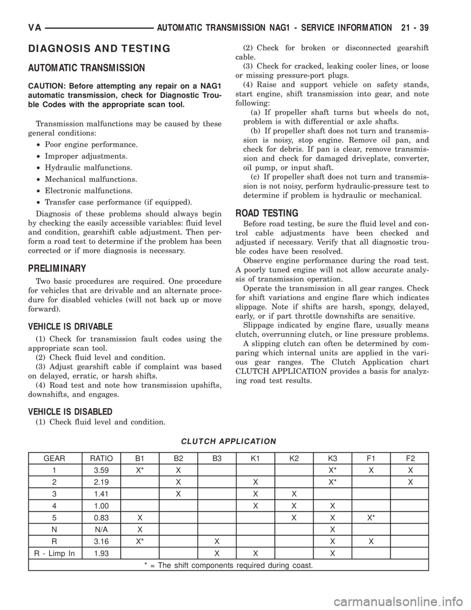
ous gear ranges. The Clutch Application chart
CLUTCH APPLICATION provides a basis for analyz-
ing road test results.
CLUTCH APPLICATION
GEAR RATIO B1 B2 B3 K1 K2 K3 F1 F2
1 3.59 X* X X* X X
2 2.19 X X X* X
3 1.41 X X X
4 1.00 X X X
5 0.83 X X X X*
N N/A X X
R 3.16 X* X X X
R - Limp In 1.93 X X X
* = The shift components required during coast.
VAAUTOMATIC TRANSMISSION NAG1 - SERVICE INFORMATION 21 - 39
Page 1801 of 2305
installed. Retaining rings are available in thick-
nesses of 2.0 mm (0.079 in.), 2.1 mm (0.083 in.), and
2.2 mm (0.087 in.).
(31) Rotate the transmission so that the bellhous-
ing is pointed upward and ensuring that the output
shaft is allowed to move freely.
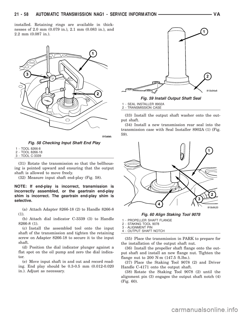
(32) Measure input shaft end-play (Fig. 58).
NOTE: If end-play is incorrect, transmission is
incorrectly assembled, or the geartrain end-play
shim is incorrect. The geartrain end-play shim is
selective.
(a) Attach Adapter 8266-18 (2) to Handle 8266-8
(1).
(b) Attach dial indicator C-3339 (3) to Handle
8266-8 (1).
(c) Install the assembled tool onto the input
shaft of the transmission and tighten the retaining
screw on Adapter 8266-18 to secure it to the input
shaft.
(d) Position the dial indicator plunger against a
flat spot on the oil pump and zero the dial indica-
tor.
(e) Move input shaft in and out and record read-
ing. End play should be 0.3-0.5 mm (0.012-0.020
in.). Adjust as necessary.(33) Install the output shaft washer onto the out-
put shaft.
(34) Install a new transmission rear seal into the
transmission case with Seal Installer 8902A (1) (Fig.
59).
(35) Place the transmission in PARK to prepare for
the installation of the output shaft nut.
(36) Install the propeller shaft flange onto the out-
put shaft and install an new flange nut. Tighten the
flange nut to 200 N´m (147.5 ft.lbs.).
(37) Place the Staking Tool 9078 (2) and Driver
Handle C-4171 onto the output shaft.
(38) Rotate the Staking Tool 9078 (2) until the
alignment pin (3) engages the output shaft notch (4)
(Fig. 60).
Fig. 58 Checking Input Shaft End Play
1 - TOOL 8266-8
2 - TOOL 8266-18
3 - TOOL C-3339
Fig. 59 Install Output Shaft Seal
1 - SEAL INSTALLER 8902A
2 - TRANSMISSION CASE
Fig. 60 Align Staking Tool 9078
1 - PROPELLER SHAFT FLANGE
2 - STAKING TOOL 9078
3 - ALIGNMENT PIN
4 - OUTPUT SHAFT NOTCH
21 - 58 AUTOMATIC TRANSMISSION NAG1 - SERVICE INFORMATIONVA
Page 1875 of 2305
CAUSES OF BURNT FLUID
Burnt, discolored fluid is a result of overheating
which has three primary causes.
1. Internal clutch slippage, usually caused by low
line pressure, inadequate clutch apply pressure, or
clutch seal failure.
2. A result of restricted fluid flow through the
main and/or auxiliary cooler. This condition is usu-
ally the result of a faulty or improperly installed
drainback valve, a damaged oil cooler, or severe
restrictions in the coolers and lines caused by debris
or kinked lines.
3. Heavy duty operation with a vehicle not prop-
erly equipped for this type of operation. Trailer tow-
ing or similar high load operation will overheat the
transmission fluid if the vehicle is improperly
equipped. Such vehicles should have an auxiliary
transmission fluid cooler, a heavy duty cooling sys-
tem, and the engine/axle ratio combination needed to
handle heavy loads.
FLUID CONTAMINATION
Transmission fluid contamination is generally a
result of:
²adding incorrect fluid
²failure to clean dipstick and fill tube when
checking level
²engine coolant entering the fluid
²internal failure that generates debris
²overheat that generates sludge (fluid break-
down)
²failure to replace contaminated converter after
repair
The use of non-recommended fluids can result in
transmission failure. The usual results are erratic
shifts, slippage, abnormal wear and eventual failure
due to fluid breakdown and sludge formation. Avoid
this condition by using recommended fluids only.
The dipstick cap and fill tube should be wiped
clean before checking fluid level. Dirt, grease and
other foreign material on the cap and tube could fall
into the tube if not removed beforehand. Take the
time to wipe the cap and tube clean before withdraw-
ing the dipstick.
Engine coolant in the transmission fluid is gener-
ally caused by a cooler malfunction. The only remedy
is to replace the radiator as the cooler in the radiator
is not a serviceable part. If coolant has circulated
through the transmission, an overhaul is necessary.
The torque converter should be replaced whenever
a failure generates sludge and debris. This is neces-
sary because normal converter flushing procedures
will not remove all contaminants.
STANDARD PROCEDURE
CHECK OIL LEVEL
(1) Verify that the vehicle is parked on a level sur-
face.
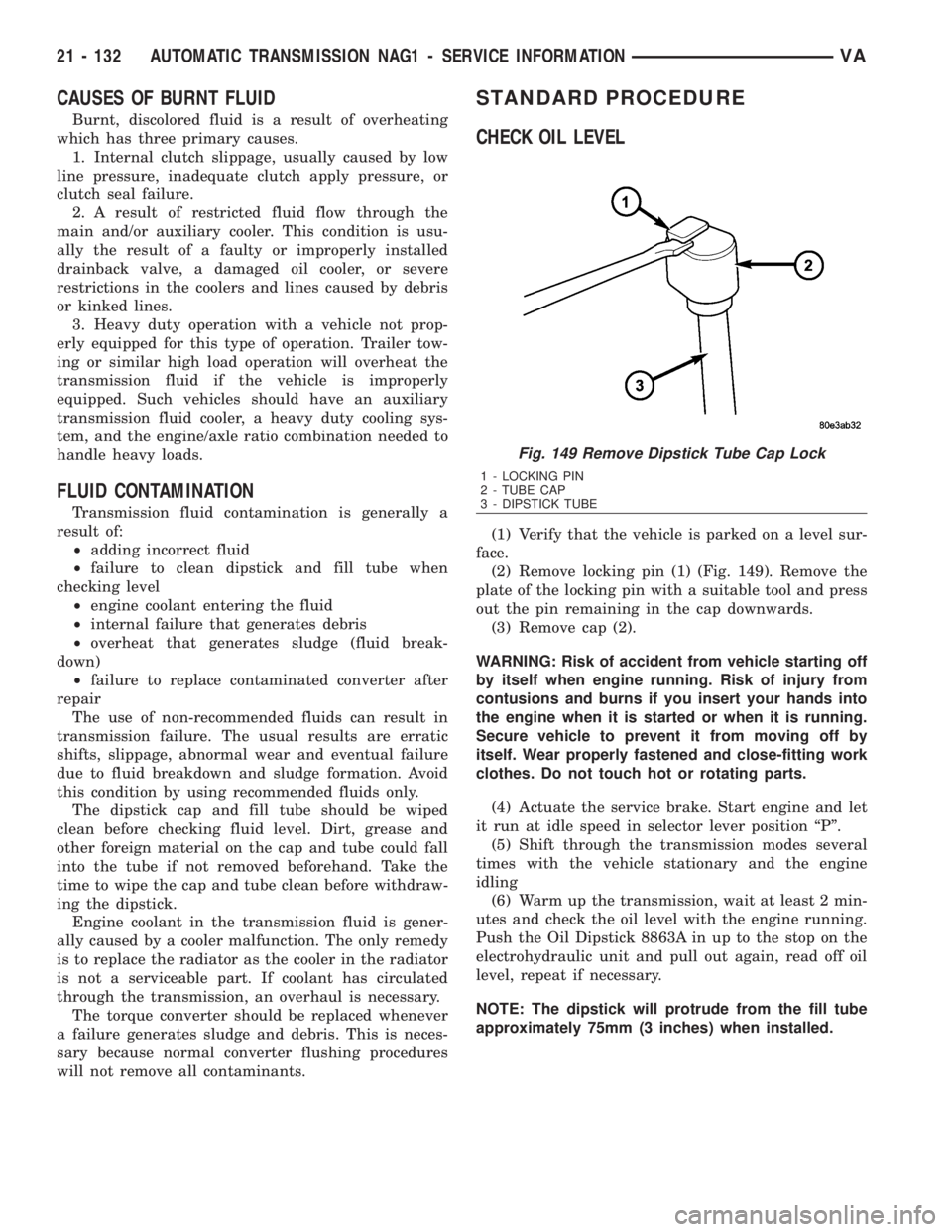
(2) Remove locking pin (1) (Fig. 149). Remove the
plate of the locking pin with a suitable tool and press
out the pin remaining in the cap downwards.
(3) Remove cap (2).
WARNING: Risk of accident from vehicle starting off
by itself when engine running. Risk of injury from
contusions and burns if you insert your hands into
the engine when it is started or when it is running.
Secure vehicle to prevent it from moving off by
itself. Wear properly fastened and close-fitting work
clothes. Do not touch hot or rotating parts.
(4) Actuate the service brake. Start engine and let
it run at idle speed in selector lever position ªPº.
(5) Shift through the transmission modes several
times with the vehicle stationary and the engine
idling
(6) Warm up the transmission, wait at least 2 min-
utes and check the oil level with the engine running.
Push the Oil Dipstick 8863A in up to the stop on the
electrohydraulic unit and pull out again, read off oil
level, repeat if necessary.
NOTE: The dipstick will protrude from the fill tube
approximately 75mm (3 inches) when installed.
Fig. 149 Remove Dipstick Tube Cap Lock
1 - LOCKING PIN
2 - TUBE CAP
3 - DIPSTICK TUBE
21 - 132 AUTOMATIC TRANSMISSION NAG1 - SERVICE INFORMATIONVA
Page 2244 of 2305
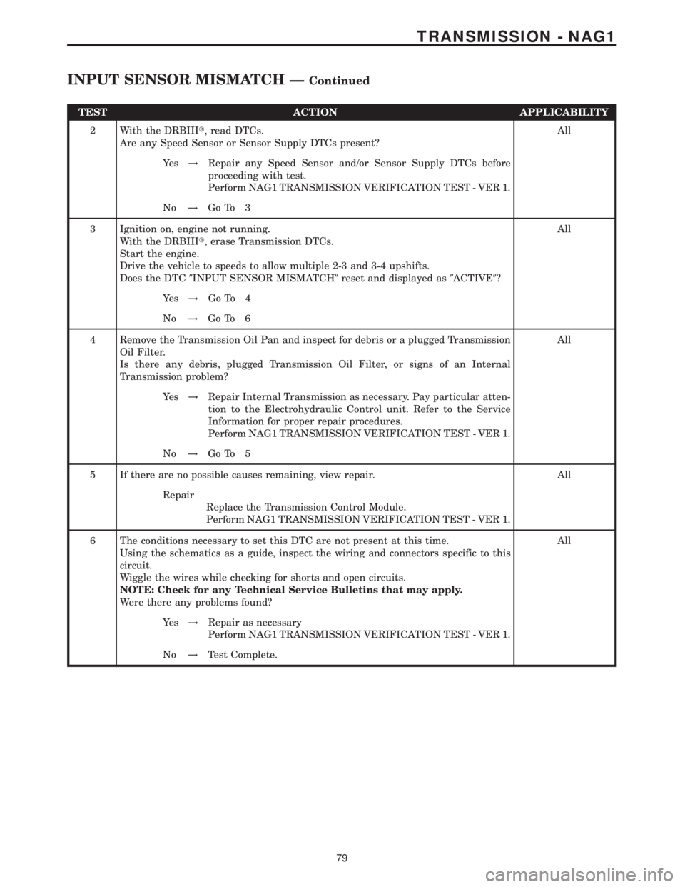
TEST ACTION APPLICABILITY
2 With the DRBIIIt, read DTCs.
Are any Speed Sensor or Sensor Supply DTCs present?All
Ye s!Repair any Speed Sensor and/or Sensor Supply DTCs before
proceeding with test.
Perform NAG1 TRANSMISSION VERIFICATION TEST - VER 1.
No!Go To 3
3 Ignition on, engine not running.
With the DRBIIIt, erase Transmission DTCs.
Start the engine.
Drive the vehicle to speeds to allow multiple 2-3 and 3-4 upshifts.
Does the DTC9INPUT SENSOR MISMATCH9reset and displayed as9ACTIVE9?All
Ye s!Go To 4
No!Go To 6
4 Remove the Transmission Oil Pan and inspect for debris or a plugged Transmission
Oil Filter.
Is there any debris, plugged Transmission Oil Filter, or signs of an Internal
Transmission problem?All
Ye s!Repair Internal Transmission as necessary. Pay particular atten-
tion to the Electrohydraulic Control unit. Refer to the Service
Information for proper repair procedures.
Perform NAG1 TRANSMISSION VERIFICATION TEST - VER 1.
No!Go To 5
5 If there are no possible causes remaining, view repair. All
Repair
Replace the Transmission Control Module.
Perform NAG1 TRANSMISSION VERIFICATION TEST - VER 1.
6 The conditions necessary to set this DTC are not present at this time.
Using the schematics as a guide, inspect the wiring and connectors specific to this
circuit.
Wiggle the wires while checking for shorts and open circuits.
NOTE: Check for any Technical Service Bulletins that may apply.
Were there any problems found?All
Ye s!Repair as necessary
Perform NAG1 TRANSMISSION VERIFICATION TEST - VER 1.
No!Test Complete.
79
TRANSMISSION - NAG1
INPUT SENSOR MISMATCH ÐContinued
Page 2246 of 2305
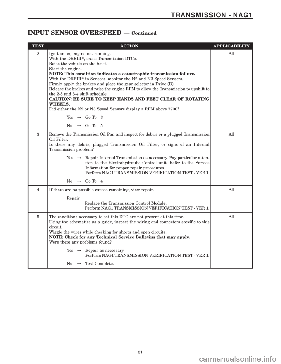
TEST ACTION APPLICABILITY
2 Ignition on, engine not running.
With the DRBIIIt, erase Transmission DTCs.
Raise the vehicle on the hoist.
Start the engine.
NOTE: This condition indicates a catastrophic transmission failure.
With the DRBIIItin Sensors, monitor the N2 and N3 Speed Sensors.
Firmly apply the brakes and place the gear selector in Drive (D).
Release the brakes and raise the engine RPM to allow the Transmission to upshift to
the 2-3 and 3-4 shift schedule.
CAUTION: BE SURE TO KEEP HANDS AND FEET CLEAR OF ROTATING
WHEELS.
Did either the N2 or N3 Speed Sensors display a RPM above 7700?All
Ye s!Go To 3
No!Go To 5
3 Remove the Transmission Oil Pan and inspect for debris or a plugged Transmission
Oil Filter.
Is there any debris, plugged Transmission Oil Filter, or signs of an Internal
Transmission problem?All
Ye s!Repair Internal Transmission as necessary. Pay particular atten-
tion to the Electrohydraulic Control unit. Refer to the Service
Information for proper repair procedures.
Perform NAG1 TRANSMISSION VERIFICATION TEST - VER 1.
No!Go To 4
4 If there are no possible causes remaining, view repair. All
Repair
Replace the Transmission Control Module.
Perform NAG1 TRANSMISSION VERIFICATION TEST - VER 1.
5 The conditions necessary to set this DTC are not present at this time.
Using the schematics as a guide, inspect the wiring and connectors specific to this
circuit.
Wiggle the wires while checking for shorts and open circuits.
NOTE: Check for any Technical Service Bulletins that may apply.
Were there any problems found?All
Ye s!Repair as necessary
Perform NAG1 TRANSMISSION VERIFICATION TEST - VER 1.
No!Test Complete.
81
TRANSMISSION - NAG1
INPUT SENSOR OVERSPEED ÐContinued