2006 MERCEDES-BENZ SPRINTER turn signal
[x] Cancel search: turn signalPage 1024 of 2305
deployment. A growling or grinding sound while
attempting to operate the seat belt retractor is a sure
indication that the seat belt tensioner has been
deployed and requires replacement. (Refer to 8 -
ELECTRICAL/RESTRAINTS/FRONT SEAT BELT &
RETRACTOR - REMOVAL).
OPERATION
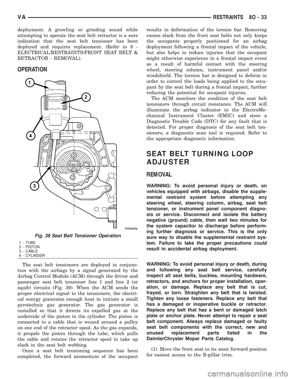
The seat belt tensioners are deployed in conjunc-
tion with the airbags by a signal generated by the
Airbag Control Module (ACM) through the driver and
passenger seat belt tensioner line 1 and line 2 (or
squib) circuits (Fig. 39). When the ACM sends the
proper electrical signal to the tensioners, the electri-
cal energy generates enough heat to initiate a small
pyrotechnic gas generator. The gas generator is
installed so that it directs its expelled gas at the
underside of the piston in the cylinder. The piston is
connected to a cable that is wound around a pulley
on one end of the retractor spool. As the gas expands,
it propels the piston through the tube, which pulls
the cable and rotates the retractor spool to take up
slack in the seat belt webbing.
Once a seat belt tensioning sequence has been
completed, the forward momentum of the occupantresults in deformation of the torsion bar. Removing
excess slack from the front seat belts not only keeps
the occupants properly positioned for an airbag
deployment following a frontal impact of the vehicle,
but also helps to reduce injuries that the occupant
might otherwise experience in a frontal impact event
as a result of harmful contact with the steering
wheel, steering column, instrument panel and/or
windshield. The torsion bar is designed to deform in
order to control the loads being applied to the occu-
pant by the seat belt during a frontal impact, further
reducing the potential for occupant injuries.
The ACM monitors the condition of the seat belt
tensioners through circuit resistance. The ACM will
illuminate the airbag indicator in the ElectroMe-
chanical Instrument Cluster (EMIC) and store a
Diagnostic Trouble Code (DTC) for any fault that is
detected. For proper diagnosis of the seat belt ten-
sioners, a diagnostic scan tool is required. Refer to
the appropriate diagnostic information.
SEAT BELT TURNING LOOP
ADJUSTER
REMOVAL
WARNING: To avoid personal injury or death, on
vehicles equipped with airbags, disable the supple-
mental restraint system before attempting any
steering wheel, steering column, airbag, seat belt
tensioner, or instrument panel component diagno-
sis or service. Disconnect and isolate the battery
negative (ground) cable, then wait two minutes for
the system capacitor to discharge before perform-
ing further diagnosis or service. This is the only
sure way to disable the supplemental restraint sys-
tem. Failure to take the proper precautions could
result in accidental airbag deployment.
WARNING: To avoid personal injury or death, during
and following any seat belt service, carefully
inspect all seat belts, buckles, mounting hardware,
retractors, and anchors for proper installation, oper-
ation, or damage. Replace any belt that is cut,
frayed, or torn. Straighten any belt that is twisted.
Tighten any loose fasteners. Replace any belt that
has a damaged or inoperative buckle or retractor.
Replace any belt that has a bent or damaged latch
plate or anchor plate. Never attempt to repair a seat
belt component. Always replace damaged or faulty
seat belt components with the correct, new and
unused replacement parts listed in the
DaimlerChrysler Mopar Parts Catalog.
(1) Move the front seat to its most forward position
for easiest access to the B-pillar trim.
Fig. 39 Seat Belt Tensioner Operation
1 - TUBE
2 - PISTON
3 - CABLE
4 - CYLINDER
VARESTRAINTS 8O - 33
Page 1035 of 2305
OPERATION
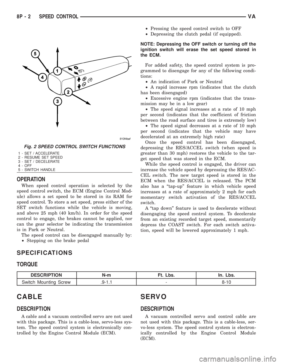
When speed control operation is selected by the
speed control switch, the ECM (Engine Control Mod-
ule) allows a set speed to be stored in its RAM for
speed control. To store a set speed, press either of the
SET switch functions while the vehicle is moving,
and above 25 mph (40 km/h). In order for the speed
control to engage, the brakes cannot be applied, nor
can the gear selector be indicating the transmission
is in Park or Neutral.
The speed control can be disengaged manually by:
²Stepping on the brake pedal²Pressing the speed control switch to OFF
²Depressing the clutch pedal (if equipped).
NOTE: Depressing the OFF switch or turning off the
ignition switch will erase the set speed stored in
the ECM.
For added safety, the speed control system is pro-
grammed to disengage for any of the following condi-
tions:
²An indication of Park or Neutral
²A rapid increase rpm (indicates that the clutch
has been disengaged)
²Excessive engine rpm (indicates that the trans-
mission may be in a low gear)
²The speed signal increases at a rate of 10 mph
per second (indicates that the coefficient of friction
between the road surface and tires is extremely low)
²The speed signal decreases at a rate of 10 mph
per second (indicates that the vehicle may have
decelerated at an extremely high rate)
Once the speed control has been disengaged,
depressing the RES/ACCEL switch (when speed is
greater than 30 mph) restores the vehicle to the tar-
get speed that was stored in the ECM.
While the speed control is engaged, the driver can
increase the vehicle speed by depressing the RES/AC-
CEL switch. The new target speed is stored in the
ECM when the RES/ACCEL is released. The PCM
also has a ªtap-upº feature in which vehicle speed
increases at a rate of approximately 2 mph for each
momentary switch activation of the RES/ACCEL
switch.
A ªtap downº feature is used to decelerate without
disengaging the speed control system. To decelerate
from an existing recorded target speed, momentarily
depress the COAST switch. For each switch activa-
tion, speed will be lowered approximately 1 mph.
SPECIFICATIONS
TORQUE
DESCRIPTION N-m Ft. Lbs. In. Lbs.
Switch Mounting Screw .9-1.1 - 8-10
CABLE
DESCRIPTION
A cable and a vacuum controlled servo are not used
with this package. This is a cable-less, servo-less sys-
tem. The speed control system is electronically con-
trolled by the Engine Control Module (ECM).
SERVO
DESCRIPTION
A vacuum controlled servo and control cable are
not used with this package. This is a cable-less, ser-
vo-less system. The speed control system is electron-
ically controlled by the Engine Control Module
(ECM).
Fig. 2 SPEED CONTROL SWITCH FUNCTIONS
1 - SET / ACCELERATE
2 - RESUME SET SPEED
3 - SET / DECELERATE
4 - OFF
5 - SWITCH HANDLE
8P - 2 SPEED CONTROLVA
Page 1038 of 2305
VEHICLE THEFT SECURITY
TABLE OF CONTENTS
page page
VEHICLE THEFT SECURITY
DESCRIPTION..........................1
OPERATION............................1
DIAGNOSIS AND TESTING - VEHICLE THEFT
SECURITY............................1
INTRUSION SENSOR
REMOVAL.............................1
INSTALLATION..........................2
SECURITY SYSTEM MODULE
REMOVAL.............................2
INSTALLATION..........................2SENTRY KEY REMOTE ENTRY MODULE
DESCRIPTION..........................2
OPERATION............................3
REMOVAL.............................3
INSTALLATION..........................4
SIREN
REMOVAL.............................4
INSTALLATION..........................4
TRANSPONDER KEY
DESCRIPTION..........................5
OPERATION............................5
VEHICLE THEFT SECURITY
DESCRIPTION
A vehicle theft alarm with a battery powered siren
is available as an option and includes interior moni-
toring, anti-tow away protection and rear window
monitoring based on the heater wires. The alarm is
automatically activated when the central locking sys-
tem is operated.
The alarm will sound when any of the following
occur:
²A door is opened
²A door is unlocked from inside the vehicle
²The hood is opened
²The vehicle is raised at the front or rear
²The trailer wire harness is disconnected
²Movements inside the vehicle
²The central locking is unlocked by a key at any
other door than the driver's door
The alarm is functional about 30 seconds after the
vehicle is locked using the RKE transmitter or the
key in the driver's door. Activation is indicated by the
indicator lights flashing three times and the warning
lamp flashing in the switch. If persons or animals
remain in the locked vehicle, the operator should
switch off the interior monitor to avoid a false alarm.
OPERATION
The anti-theft alarm is activated/deactivated by
locking/unlocking the vehicle with the remote trans-
mitter or with the key at the driver's door. The key
must be held in the locking position for more than
two seconds. Activation is indicated by the turn sig-
nal lights flashing once. Unlocking the vehicle at one
of the other doors will trigger an alarm.
The interior monitoring system included in the
anti-theft alarm is based on ultrasonics and triggersan alarm if an object intrudes the interior of the
vehicle or if any movement is detected inside the
vehicle. For proper and effective protection, all win-
dows and the sunroof must be closed.
To switch off the interior monitoring system and /
or the anti-tow away protection, a switch with LED
indicator light is provided in the switch panel. An
alarm button enables the operator to trigger an
alarm manually and to lock all doors if they are
closed. Triggering an alarm makes the horn sound
and the turn signals flash until the alarm is switched
off.
The anti-theft alarm control unit includes a gradi-
ent indicator as anti-tow away protection. The gradi-
ent indicator triggers an audible and visual alarm if
the vehicle is lifted (to tow away or to remove the
wheels). The alarm remains effective even if the bat-
tery is disconnected as the horn is powered by its
own battery. The interior monitoring system should
be switched off if people and/or animals are left in
the vehicle.
DIAGNOSIS AND TESTING - VEHICLE THEFT
SECURITY
Any diagnosis of the Vehicle Theft Security
system should begin with the use of a diagnos-
tic scan tool. Refer to the appropriate diagnos-
tic information.
INTRUSION SENSOR
REMOVAL
(1) Disconnect and isolate the battery negative
cable.
(2) Insert the tip of a small flat-bladed screwdriver
into the notch on one edge of the dome lamp/intru-
sion sensor unit housing to depress the retainer clip
VAVEHICLE THEFT SECURITY 8Q - 1
Page 1040 of 2305
REMOTE KEYLESS ENTRY (RKE)
The RKE transmitter uses radio frequency signals
to communicate with the Sentry Key Remote Entry
Module (SKREEM). The SKREEM is hardwired to
the Central Timer Module (CTM). When the operator
presses a button on the transmitter, it sends a spe-
cific request to the SKREEM. In turn, the SKREEM
sends the appropriate request to the CTM to unlock
the vehicle doors.
OPERATION
SENTRY KEY IMMOBILIZER
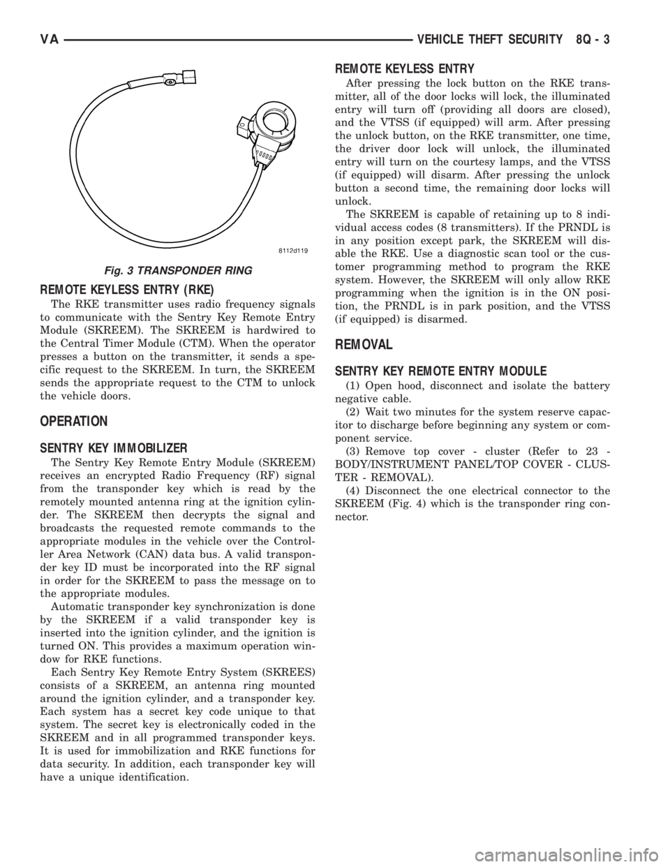
The Sentry Key Remote Entry Module (SKREEM)
receives an encrypted Radio Frequency (RF) signal
from the transponder key which is read by the
remotely mounted antenna ring at the ignition cylin-
der. The SKREEM then decrypts the signal and
broadcasts the requested remote commands to the
appropriate modules in the vehicle over the Control-
ler Area Network (CAN) data bus. A valid transpon-
der key ID must be incorporated into the RF signal
in order for the SKREEM to pass the message on to
the appropriate modules.
Automatic transponder key synchronization is done
by the SKREEM if a valid transponder key is
inserted into the ignition cylinder, and the ignition is
turned ON. This provides a maximum operation win-
dow for RKE functions.
Each Sentry Key Remote Entry System (SKREES)
consists of a SKREEM, an antenna ring mounted
around the ignition cylinder, and a transponder key.
Each system has a secret key code unique to that
system. The secret key is electronically coded in the
SKREEM and in all programmed transponder keys.
It is used for immobilization and RKE functions for
data security. In addition, each transponder key will
have a unique identification.
REMOTE KEYLESS ENTRY
After pressing the lock button on the RKE trans-
mitter, all of the door locks will lock, the illuminated
entry will turn off (providing all doors are closed),
and the VTSS (if equipped) will arm. After pressing
the unlock button, on the RKE transmitter, one time,
the driver door lock will unlock, the illuminated
entry will turn on the courtesy lamps, and the VTSS
(if equipped) will disarm. After pressing the unlock
button a second time, the remaining door locks will
unlock.
The SKREEM is capable of retaining up to 8 indi-
vidual access codes (8 transmitters). If the PRNDL is
in any position except park, the SKREEM will dis-
able the RKE. Use a diagnostic scan tool or the cus-
tomer programming method to program the RKE
system. However, the SKREEM will only allow RKE
programming when the ignition is in the ON posi-
tion, the PRNDL is in park position, and the VTSS
(if equipped) is disarmed.
REMOVAL
SENTRY KEY REMOTE ENTRY MODULE
(1) Open hood, disconnect and isolate the battery
negative cable.
(2) Wait two minutes for the system reserve capac-
itor to discharge before beginning any system or com-
ponent service.
(3) Remove top cover - cluster (Refer to 23 -
BODY/INSTRUMENT PANEL/TOP COVER - CLUS-
TER - REMOVAL).
(4) Disconnect the one electrical connector to the
SKREEM (Fig. 4) which is the transponder ring con-
nector.
Fig. 3 TRANSPONDER RING
VAVEHICLE THEFT SECURITY 8Q - 3
Page 1042 of 2305
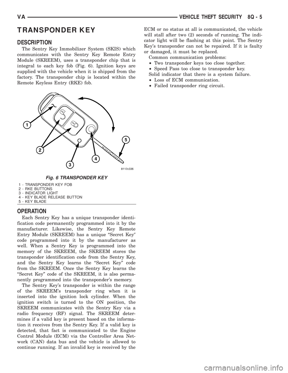
TRANSPONDER KEY
DESCRIPTION
The Sentry Key Immobilizer System (SKIS) which
communicates with the Sentry Key Remote Entry
Module (SKREEM), uses a transponder chip that is
integral to each key fob (Fig. 6). Ignition keys are
supplied with the vehicle when it is shipped from the
factory. The transponder chip is located within the
Remote Keyless Entry (RKE) fob.
OPERATION
Each Sentry Key has a unique transponder identi-
fication code permanently programmed into it by the
manufacturer. Likewise, the Sentry Key Remote
Entry Module (SKREEM) has a unique ªSecret Key9
code programmed into it by the manufacturer as
well. When a Sentry Key is programmed into the
memory of the SKREEM, the SKREEM stores the
transponder identification code from the Sentry Key,
and the Sentry Key learns the ªSecret Keyº code
from the SKREEM. Once the Sentry Key learns the
ªSecret Keyº code of the SKREEM, it is also perma-
nently programmed into the transponder's memory.
The Sentry Key's transponder is within the range
of the SKREEM's transponder ring when it is
inserted into the ignition lock cylinder. When the
ignition switch is turned to the ON position, the
SKREEM communicates with the Sentry Key via a
radio frequency (RF) signal. The SKREEM deter-
mines if a valid key is present based on the informa-
tion it receives from the Sentry Key. If a valid key is
detected, that fact is communicated to the Engine
Control Module (ECM) via the Controller Area Net-
work (CAN) data bus and the vehicle is allowed to
continue running. If an invalid key is received by theECM or no status at all is communicated, the vehicle
will stall after two (2) seconds of running. The indi-
cator light will be flashing at this point. The Sentry
Key's transponder can not be repaired. If it is faulty
or damaged, it must be replaced.
Common communication problems:
²Two transponder keys too close together.
²Speed Pass too close to transponder key.
Solid indicator that there is a system failure.
²Loss of ECM communication.
²Failed transponder ring circuit.
Fig. 6 TRANSPONDER KEY
1 - TRANSPONDER KEY FOB
2 - RKE BUTTONS
3 - INDICATOR LIGHT
4 - KEY BLADE RELEASE BUTTON
5 - KEY BLADE
VAVEHICLE THEFT SECURITY 8Q - 5
Page 1046 of 2305
both the wiper and washer systems. (Refer to 8 -
ELECTRICAL/LAMPS/LIGHTING - EXTERIOR/
MULTI-FUNCTION SWITCH - DESCRIPTION)
²Rain Sensor- Vehicles equipped with an
optional automatic wiper feature have an electronic
rain sensor concealed within the base of the rear
view mirror unit on the inside of the laminated wind-
shield glass.
²Rain Sensor Control Module- Vehicles
equipped with an optional automatic wiper feature
have an electronic rain sensor control module located
under the lower instrument panel above the acceler-
ator pedal in the passenger compartment of the vehi-
cle.
²Washer Fluid Level Switch- The optional
washer fluid level switch is integral to a unique ver-
sion of the washer pump/motor unit, which is located
in a dedicated hole on the top of the sump area near
the back of the windshield washer reservoir on the
right front fender wheel house in the engine com-
partment.
²Washer Nozzle- A single washer nozzle with
three separate orifices is secured with integral snap
features to each wiper arm. The hoses for the washer
nozzles are concealed beneath a molded plastic guide
on the underside of each wiper arm and routed to the
engine compartment through unique molded plastic
elbow fittings located near each wiper pivot at the
base of the windshield.
²Washer Pump/Motor- Two different washer
pump/motor units are available for this model. One
version has an integral washer fluid level switch that
provides a hard wired input to the instrument cluster
for control of the optional washer fluid indicator. The
washer pump/motor unit is located in a dedicated
hole on the top of the sump area near the back of the
windshield washer reservoir on the right front fender
wheel house in the engine compartment.
²Washer Reservoir- The washer reservoir is
located on the right front fender wheel house in the
engine compartment. The washer reservoir filler is
accessed from the right front corner of the engine
compartment.
²Wiper Arm- The two unequal length wiper
arms are secured to the two wiper pivots, which
extend through the cowl panel near the base of the
windshield. The longer arm is installed on the left
(driver) side of the windshield.
²Wiper Blade- The two unequal length wiper
blades are secured to the two wiper arms, and are
parked on the glass near the bottom of the wind-
shield when the wiper system is not in operation.
The longer blade is installed on the left (driver) side
of the windshield.
²Wiper Linkage- The wiper pivots are the only
visible components of the wiper linkage. The remain-
der of the linkage is concealed within the engine
compartment just behind the hood opening. Thewiper linkage module includes the two wiper drive
links, the wiper motor crank arm, the two wiper piv-
ots, and the linkage and motor mounting bracket.
²Wiper Motor- The wiper motor is secured to
the wiper linkage module bracket on the underside of
the cowl panel within the engine compartment. The
wiper motor output shaft and crank arm extend
through a clearance hole in the mounting bracket,
where they are connected to a crank arm that drives
the wiper linkage.
²Wiper Relay- The wiper relay is located in a
dedicated receptacle on the lower left surface of the
fuse block underneath the steering column behind
the fuse access panel and the steering column open-
ing panel. The wiper relay is a passive component on
vehicles equipped with the optional automatic wiper
system.
²Wiper, Turn Signals, Engine Start Control
Module- The wiper, turn signals and engine start
control module is integral to the fuse block located
underneath the steering column. The fuse block is
concealed behind the fuse access panel and the steer-
ing column opening panel, where it is secured with
screws to the steering column. The wiper system
functions of this module are passive on vehicles
equipped with the optional automatic wiper system.
Hard wired circuitry connects the wiper and
washer system components to the electrical system of
the vehicle. These hard wired circuits are integral to
several wire harnesses, which are routed throughout
the vehicle and retained by many different methods.
These circuits may be connected to each other, to the
vehicle electrical system and to the wiper and washer
system components through the use of a combination
of soldered splices, splice block connectors, and many
different types of wire harness terminal connectors
and insulators. Refer to the appropriate wiring infor-
mation. The wiring information includes wiring dia-
grams, proper wire and connector repair procedures,
further details on wire harness routing and reten-
tion, as well as pin-out and location views for the
various wire harness connectors, splices and grounds.
OPERATION
The wiper and washer system is designed to pro-
vide the vehicle operator with a convenient, safe, and
reliable means of maintaining visibility through the
windshield glass. The various components of this sys-
tem are designed to convert electrical energy pro-
duced by the vehicle electrical system into the
mechanical action of the wiper blades to wipe the
outside surface of the glass, as well as into the
hydraulic action of the washer system to apply
washer fluid stored in an on-board reservoir to the
area of the glass to be wiped. When combined, these
components provide the means to effectively main-
tain clear visibility for the vehicle operator by remov-
ing excess accumulations of rain, snow, bugs, mud, or
VAWIPERS/WASHERS 8R - 3
Page 1047 of 2305
other minor debris from the outside windshield glass
surface that might be encountered while driving the
vehicle under numerous types of inclement operating
conditions.
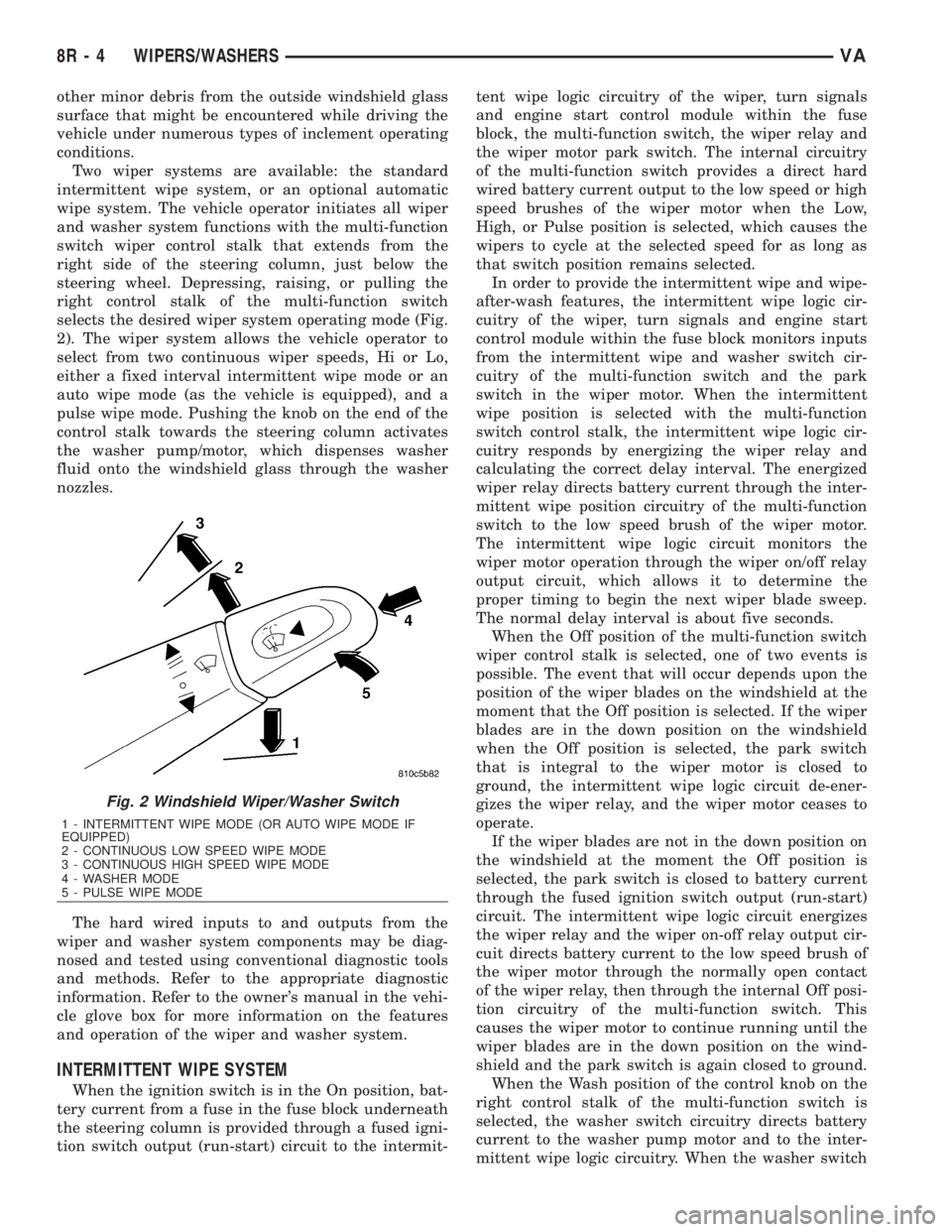
Two wiper systems are available: the standard
intermittent wipe system, or an optional automatic
wipe system. The vehicle operator initiates all wiper
and washer system functions with the multi-function
switch wiper control stalk that extends from the
right side of the steering column, just below the
steering wheel. Depressing, raising, or pulling the
right control stalk of the multi-function switch
selects the desired wiper system operating mode (Fig.
2). The wiper system allows the vehicle operator to
select from two continuous wiper speeds, Hi or Lo,
either a fixed interval intermittent wipe mode or an
auto wipe mode (as the vehicle is equipped), and a
pulse wipe mode. Pushing the knob on the end of the
control stalk towards the steering column activates
the washer pump/motor, which dispenses washer
fluid onto the windshield glass through the washer
nozzles.
The hard wired inputs to and outputs from the
wiper and washer system components may be diag-
nosed and tested using conventional diagnostic tools
and methods. Refer to the appropriate diagnostic
information. Refer to the owner's manual in the vehi-
cle glove box for more information on the features
and operation of the wiper and washer system.
INTERMITTENT WIPE SYSTEM
When the ignition switch is in the On position, bat-
tery current from a fuse in the fuse block underneath
the steering column is provided through a fused igni-
tion switch output (run-start) circuit to the intermit-tent wipe logic circuitry of the wiper, turn signals
and engine start control module within the fuse
block, the multi-function switch, the wiper relay and
the wiper motor park switch. The internal circuitry
of the multi-function switch provides a direct hard
wired battery current output to the low speed or high
speed brushes of the wiper motor when the Low,
High, or Pulse position is selected, which causes the
wipers to cycle at the selected speed for as long as
that switch position remains selected.
In order to provide the intermittent wipe and wipe-
after-wash features, the intermittent wipe logic cir-
cuitry of the wiper, turn signals and engine start
control module within the fuse block monitors inputs
from the intermittent wipe and washer switch cir-
cuitry of the multi-function switch and the park
switch in the wiper motor. When the intermittent
wipe position is selected with the multi-function
switch control stalk, the intermittent wipe logic cir-
cuitry responds by energizing the wiper relay and
calculating the correct delay interval. The energized
wiper relay directs battery current through the inter-
mittent wipe position circuitry of the multi-function
switch to the low speed brush of the wiper motor.
The intermittent wipe logic circuit monitors the
wiper motor operation through the wiper on/off relay
output circuit, which allows it to determine the
proper timing to begin the next wiper blade sweep.
The normal delay interval is about five seconds.
When the Off position of the multi-function switch
wiper control stalk is selected, one of two events is
possible. The event that will occur depends upon the
position of the wiper blades on the windshield at the
moment that the Off position is selected. If the wiper
blades are in the down position on the windshield
when the Off position is selected, the park switch
that is integral to the wiper motor is closed to
ground, the intermittent wipe logic circuit de-ener-
gizes the wiper relay, and the wiper motor ceases to
operate.
If the wiper blades are not in the down position on
the windshield at the moment the Off position is
selected, the park switch is closed to battery current
through the fused ignition switch output (run-start)
circuit. The intermittent wipe logic circuit energizes
the wiper relay and the wiper on-off relay output cir-
cuit directs battery current to the low speed brush of
the wiper motor through the normally open contact
of the wiper relay, then through the internal Off posi-
tion circuitry of the multi-function switch. This
causes the wiper motor to continue running until the
wiper blades are in the down position on the wind-
shield and the park switch is again closed to ground.
When the Wash position of the control knob on the
right control stalk of the multi-function switch is
selected, the washer switch circuitry directs battery
current to the washer pump motor and to the inter-
mittent wipe logic circuitry. When the washer switch
Fig. 2 Windshield Wiper/Washer Switch
1 - INTERMITTENT WIPE MODE (OR AUTO WIPE MODE IF
EQUIPPED)
2 - CONTINUOUS LOW SPEED WIPE MODE
3 - CONTINUOUS HIGH SPEED WIPE MODE
4 - WASHER MODE
5 - PULSE WIPE MODE
8R - 4 WIPERS/WASHERSVA
Page 1048 of 2305
is closed with the wiper system turned Off, the inter-
mittent wipe logic circuitry operates the wiper motor
in the same manner as it does to provide the inter-
mittent wipe mode operation. After the state of the
washer switch changes to open, the intermittent wipe
logic circuitry monitors the wiper motor through the
wiper on-off relay output circuit, which allows it to
monitor the number of wiper blade sweeps. After the
appropriate number of wiper sweeps the intermittent
wipe logic circuitry operates the wiper motor to
return the wipers to their park position, then de-en-
ergizes the wiper relay.
AUTOMATIC WIPE SYSTEM
When the ignition switch is in the On position, bat-
tery current from a fuse in the fuse block underneath
the steering column is provided through a fused igni-
tion switch output (run-start) circuit to the rain sen-
sor control module under the instrument panel, to
the rain sensor within the base of the inside rear
view mirror on the windshield, and to the multi-func-
tion switch. The internal circuitry of the multi-func-
tion switch provides direct hard wired battery
current outputs to the rain sensor control module to
indicate the selected wiper operating mode. The con-
trol module logic monitors the inputs from the multi-
function switch as well as from the rain sensor and
the wiper motor park switch in order to provide the
outputs necessary to operate the wiper motor and the
washer pump motor as requested.
When the automatic wipe position is selected with
the multi-function switch control stalk, the rain sen-
sor control module logic circuitry responds by provid-
ing an acknowledgment sweep of the wipers. The
rain sensor calculates the correct wiper speed and
wiper sweep intervals required to remove the mois-
ture detected on the windshield glass and provides
this input to the rain sensor control module. The con-
trol module then energizes and de-energizes the
wiper motor automatically. The automatic wipe logic
will also provide a wipe-after-wash feature to clear
washer fluid that is directed onto the windshield
when the washer system is utilized.
When the Off position of the multi-function switch
wiper control stalk is selected, one of two events is
possible. The event that will occur depends upon the
position of the wiper blades on the windshield at the
moment that the Off position is selected. If the wiper
blades are in the down position on the windshield
when the Off position is selected, the park switch
that is integral to the wiper motor is closed to
ground, and the rain sensor control module logic cir-
cuit de-energizes the wiper motor. If the wiper blades
are not in the down position at the moment the Off
position is selected, the park switch is an open cir-
cuit. The control module logic circuit directs battery
current to the low speed brush of the wiper motor,
which causes the wiper motor to continue runninguntil the wiper blades are in the down position on
the windshield and the park switch is again closed to
ground.
When the Wash position of the control knob on the
right control stalk of the multi-function switch is
selected with the wiper system turned Off, the rain
sensor control module logic circuitry operates the
wiper motor in the same manner as it does to provide
the automatic wipe mode operation. After the state of
the washer switch changes to open the control mod-
ule monitors the wiper motor through the wiper park
switch sense circuit, which allows it to monitor the
number of wiper blade sweeps. After the appropriate
number of wiper sweeps the control module operates
the wiper motor to return the wipers to their park
position, then de-energizes the wiper motor.
OPERATING MODES
The components of the wiper and washer system
are designed to provide the following operating
modes:
²Automatic Wipe Mode- On vehicles so
equipped, the internal circuitry of the multi-function
switch, the rain sensor control module and the rain
sensor work in concert to provide wiper system oper-
ation automatically whenever moisture is detected on
the windshield glass.
²Continuous Wipe Mode- The two-speed wiper
motor, the internal circuitry of the multi-function
switch, and the wiper system logic circuits work in
concert to provide two continuous wipe cycles, low
speed or high speed.
²Intermittent Wipe Mode- On vehicles so
equipped, the internal circuitry of the multi-function
switch, the intermittent wipe circuitry of the wiper,
turn signals and engine start control module in the
fuse block, and the wiper relay work in concert to
provide an intermittent wipe mode with a single,
fixed delay interval.
²Pulse Wipe Mode- The internal circuitry of
the multi-function switch and the wiper system logic
circuits work in concert to provide a pulse wipe mode
that will allow the wiper motor to be operated for a
single, complete wipe cycle.
²Washer Mode- When the washer system is
activated with the multi-function switch while the
wiper system is operating, washer fluid will be dis-
pensed onto the windshield glass through the washer
nozzles for as long as the washer pump/motor is
energized.
²Wipe-After-Wash Mode- The wiper system
logic circuitry provides a wipe-after-wash feature. If
the wipers are turned Off, this feature will operate
the washer pump/motor and the wipers for as long as
the washer system is activated, then provide several
additional wipe cycles after the washer system is
deactivated before parking the wiper blades near the
base of the windshield.
VAWIPERS/WASHERS 8R - 5