Page 1584 of 2305
NOTE: After removing the front cross plate, seal
metal with anti corrosion protection.
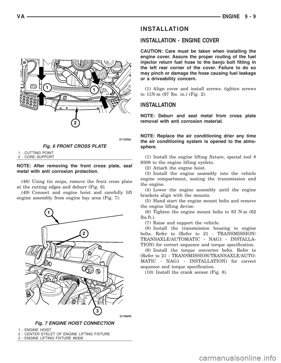
(48) Using tin snips, remove the front cross plate
at the cutting edges and deburr (Fig. 6).
(49) Connect and engine hoist and carefully lift
engine assembly from engine bay area (Fig. 7).
INSTALLATION
INSTALLATION - ENGINE COVER
CAUTION: Care must be taken when installing the
engine cover. Assure the proper routing of the fuel
injector return fuel hose to the banjo bolt fitting in
the left rear corner of the cover. Failure to do so
may pinch or damage the hose causing fuel leakage
or a driveability concern.
(1) Align cover and install screws. tighten screws
to 11N´m (97 lbs. in.) (Fig. 2).
INSTALLATION
NOTE: Deburr and seal metal from cross plate
removal with anti corrosion material.
NOTE: Replace the air conditioning drier any time
the air conditioning system is opened to the atmo-
sphere.
(1) Install the engine lifting fixture, special tool #
9308 to the engine lifting eyelets.
(2) Attach the engine hoist.
(3) Install the engine assembly into the vehicle
engine compartment, mating the transmission and
the engine.
(4) Lower the engine assembly until the engine
brackets align with the mounts.
(5) Hand start the engine mount bolts and remove
the engine lifting devise.
(6) Tighten the engine mount bolts to 83 N´m (62
lbs.ft.).
(7) Raise and support the vehicle.
(8) Install the transmission housing to engine
bolts. Refer to (Refer to 21 - TRANSMISSION/
TRANSAXLE/AUTOMATIC - NAG1 - INSTALLA-
TION) for correct sequence and torque specification.
(9) Install the torque converter bolts. Refer to
(Refer to 21 - TRANSMISSION/TRANSAXLE/AUTO-
MATIC - NAG1 - INSTALLATION) for correct
sequence and torque specification.
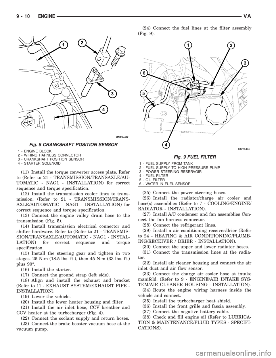
(10) Install the crank sensor (Fig. 8).
Fig. 6 FRONT CROSS PLATE
1 - CUTTING POINT
2 - CORE SUPPORT
Fig. 7 ENGINE HOIST CONNECTION
1 - ENGINE HOIST
2 - CENTER EYELET OF ENGINE LIFTING FIXTURE
3 - ENGINE LIFTING FIXTURE #9308
VAENGINE 9 - 9
Page 1585 of 2305
(11) Install the torque converter access plate. Refer
to (Refer to 21 - TRANSMISSION/TRANSAXLE/AU-
TOMATIC - NAG1 - INSTALLATION) for correct
sequence and torque specification.
(12) Install the transmission cooler lines to trans-
mission. (Refer to 21 - TRANSMISSION/TRANS-
AXLE/AUTOMATIC - NAG1 - INSTALLATION) for
correct sequence and torque specification.
(13) Connect the engine valley drain hose to the
transmission (Fig. 5).
(14) Install transmission electrical connector and
shifter hardware. Refer to (Refer to 21 - TRANSMIS-
SION/TRANSAXLE/AUTOMATIC - NAG1 - INSTAL-
LATION) for correct sequence and torque
specification.
(15) Install the steering gear and tighten in two
stages. 25 N´m (18.5 lbs. ft.), then 45 N´m (33 lbs. ft.)
plus 90É.
(16) Install the starter.
(17) Connect the ground strap (left side).
(18) Align and install the exhaust and bracket
(Refer to 11 - EXHAUST SYSTEM/EXHAUST PIPE -
INSTALLATION).
(19) Lower the vehicle.
(20) Install the lower heater housing and filter.
(21) Install the air inlet hose, CCV breather and
CCV heater at the turbocharger (Fig. 4).
(22) Connect the coolant supply and return hoses.
(23) Connect the brake booster vacuum hose at the
vacuum pump.(24) Connect the fuel lines at the filter assembly
(Fig. 9).
(25) Connect the power steering hoses.
(26) Install the radiator/charge air cooler and
hose(s) assemblies (Refer to 7 - COOLING/ENGINE/
RADIATOR - INSTALLATION).
(27) Install A/C condenser and fan assemblies Con-
nect the fan harness connector.
(28) Connect the refrigerant lines.
(29) Install a air conditioning receiver/drier (Refer
to 24 - HEATING & AIR CONDITIONING/PLUMB-
ING/RECEIVER / DRIER - INSTALLATION).
(30) Connect the upper and lower radiator hoses.
(31) Connect the transmission lines at the radia-
tor.
(32) Install air cleaner housing and connect the air
inlet duct and air flow sensor.
(33) Connect the charge air cooler hose at intake
manifold. (Refer to 9 - ENGINE/AIR INTAKE SYS-
TEM/AIR CLEANER HOUSING - INSTALLATION).
(34) Route the engine wiring harness inside the
vehicle and connect.
(35) Install the turbocharger heat shield.
(36) Install the front grille and fascia assembly.
(37) Connect the negative battery cable.
(38) Check and fill engine oil (Refer to LUBRICA-
TION & MAINTENANCE/FLUID TYPES - SPECIFI-
CATIONS).
Fig. 8 CRANKSHAFT POSITION SENSOR
1 - ENGINE BLOCK
2 - WIRING HARNESS CONNECTOR
3 - CRANKSHAFT POSITION SENSOR
4 - STARTER SOLENOID
Fig. 9 FUEL FILTER
1 - FUEL SUPPLY FROM TANK
2 - FUEL SUPPLY TO HIGH PRESSURE PUMP
3 - POWER STEERING RESERVOIR
4 - FUEL FILTER
5 - OIL FILTER
6 - WATER IN FUEL SENSOR
9 - 10 ENGINEVA
Page 1586 of 2305
(39) Fill cooling system to proper level with the
appropriate coolant.
(40) Evacuate and recharge air conditioning.
(41) Check and refill all ancillary system fluid lev-
els.(42) Start engine and inspect for leaks (Refer to 14
- FUEL SYSTEM - WARNING).
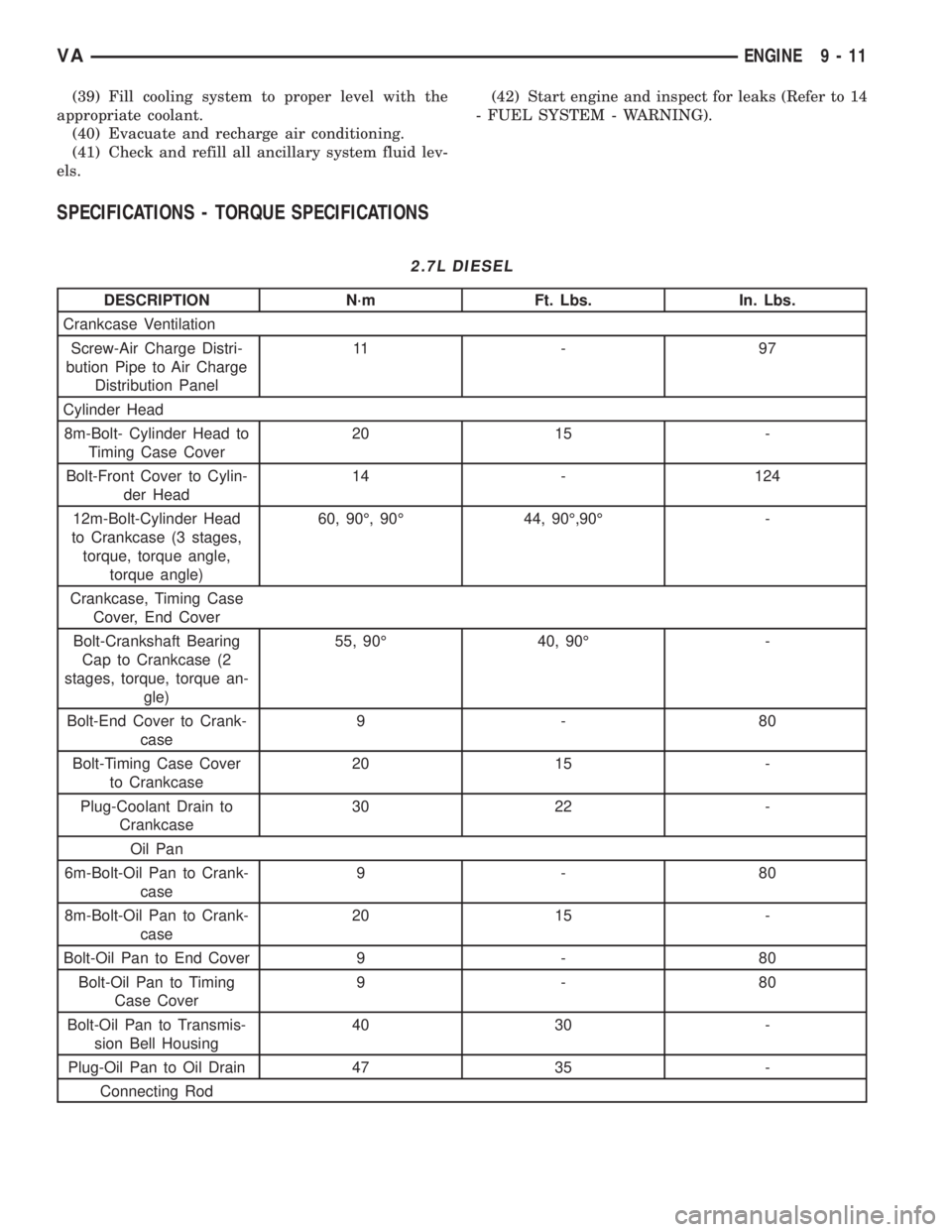
SPECIFICATIONS - TORQUE SPECIFICATIONS
2.7L DIESEL
DESCRIPTION N´m Ft. Lbs. In. Lbs.
Crankcase Ventilation
Screw-Air Charge Distri-
bution Pipe to Air Charge
Distribution Panel11 - 9 7
Cylinder Head
8m-Bolt- Cylinder Head to
Timing Case Cover20 15 -
Bolt-Front Cover to Cylin-
der Head14 - 124
12m-Bolt-Cylinder Head
to Crankcase (3 stages,
torque, torque angle,
torque angle)60, 90É, 90É 44, 90É,90É -
Crankcase, Timing Case
Cover, End Cover
Bolt-Crankshaft Bearing
Cap to Crankcase (2
stages, torque, torque an-
gle)55, 90É 40, 90É -
Bolt-End Cover to Crank-
case9-80
Bolt-Timing Case Cover
to Crankcase20 15 -
Plug-Coolant Drain to
Crankcase30 22 -
Oil Pan
6m-Bolt-Oil Pan to Crank-
case9-80
8m-Bolt-Oil Pan to Crank-
case20 15 -
Bolt-Oil Pan to End Cover 9 - 80
Bolt-Oil Pan to Timing
Case Cover9-80
Bolt-Oil Pan to Transmis-
sion Bell Housing40 30 -
Plug-Oil Pan to Oil Drain 47 35 -
Connecting Rod
VAENGINE 9 - 11
Page 1589 of 2305
DESCRIPTION N´m Ft. Lbs. In. Lbs.
Oil Filter
Screw Cap to Oil Filter 25 18.5 -
Oil Cooling System
Bolt-Oil-Water Heat Ex-
changer to Timing Cover
Case15 - 133
Oil Level Pressure
Bolt-Dip Stick Guide Tube
to Cylinder Head14 - 123
Bolt-Oil Level Sensor to
Oil Pan14 - 123
Coolant Pre-Heater
Coolant Pre-Heater in En-
gine Block35 26 -
Engine Cooling General
Bolt-Belt Pulley to Coolant
Pump8-35 6 - 26 -
Bolt-Coolant Pump to
Timing Case Cover 6m/
8m14/20 10 - 15 -
Bolt-Thremostat Housing
to Cylinder Head9-80
Coolant Drain Plug to
Crankcase30 22 -
Engine Suspension, Engine Mount, Engine Bracket
Bolt-Engine Bracket to
Crankcase (2 stage,
torque, torque angle)20/90É 15, 90É -
Bolt-Engine Mount to En-
gine Bracket55 40.5 -
Bolt-Front Engine Mount
to Front Axle Carrier35 26 -
Bolt-Rear Engine Cross
Member to Body40 30 -
Bolt-Rear Engine Mount
to Rear Engine Cross
Member35 26 -
Bolt/Nut- Rear Engine
Mount to Transmission40 26 -
Bolt-Shrowd to Engine
Bracket10 - 88.5
Nut-Front Engine Mount
to Engine Bracket65 48 -
Nut-Engine Mount to Ve-
hicle Frame35 26 -
Fuel Filter
Bolt-Clip to Fuel Filter 8 - 70
9 - 14 ENGINEVA
Page 1590 of 2305
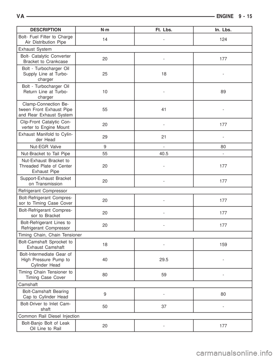
DESCRIPTION N´m Ft. Lbs. In. Lbs.
Bolt- Fuel Filter to Charge
Air Distribution Pipe14 - 124
Exhaust System
Bolt- Catalytic Converter
Bracket to Crankcase20 - 177
Bolt - Turbocharger Oil
Supply Line at Turbo-
charger25 18 -
Bolt - Turbocharger Oil
Return Line at Turbo-
charger10 - 89
Clamp-Connection Be-
tween Front Exhaust Pipe
and Rear Exhaust System55 41 -
Clip-Front Catalytic Con-
verter to Engine Mount20 - 177
Exhaust Manifold to Cylin-
der Head29 21 -
Nut-EGR Valve 9 - 80
Nut-Bracket to Tail Pipe 55 40.5 -
Nut-Exhaust Bracket to
Threaded Plate of Center
Exhaust Pipe20 - 177
Support-Exhaust Bracket
on Transmission20 - 177
Refrigerant Compressor
Bolt-Refrigerant Compres-
sor to Timing Case Cover20 - 177
Bolt-Refrigerant Compres-
sor to Bracket20 - 177
Bolt-Refrigerant Lines to
Refrigerant Compressor20 - 177
Timing Chain, Chain Tensioner
Bolt-Camshaft Sprocket to
Exhaust Camshaft18 - 159
Bolt-Intermediate Gear of
High Pressure Pump to
Cylinder Head40 29.5 -
Timing Chain Tensioner to
Timing Case Cover80 59 -
Camshaft
Bolt-Camshaft Bearing
Cap to Cylinder Head9-80
Bolt-Driver to Inlet Cam-
shaft50 37 -
Common Rail Diesel Injection
Bolt-Banjo Bolt of Leak
Oil Line to Rail20 - 177
VAENGINE 9 - 15
Page 1591 of 2305
DESCRIPTION N´m Ft. Lbs. In. Lbs.
Bolt-Bracket to High Pres-
sure Pump9-80
Bolt-High Pressure Pump
to Cylinder Head14 - 124
Bolt-Pre-delivery Pump to
Top Cover of Cylinder
Head9-80
Bolt-Pressure Control
Valve to Rail (2 stage,
torque)3/5 - 26/44
Bolt-Rail to Cylinder Head 14 - 124
Bolt-Shutoff Valve to Cyl-
inder Head8-70
Nut-Pressure Line to Rail/
Injector (New,Reused)22/25 16/18.5 -
Nut-Pressure Line to High
Pressure Pump/Rail22 16 -
Screw-Tensioning Claw to
Injector (2 stage, 1
torque, 1 torque angle)7/90É - 62, 90É
Rail-Pressure Sensor to
Rail22 16 -
Pressure Pipe Connection
to Injector42 31 -
Threaded Rail to Rail 22 16 -
Fuel Cooling System
Bolt-Fuel Cooler to
Charge Air Distribution
Pipe14 - 124
Heater Booster, Heater Unit
Bolt- Temperature Con-
trolled Cut Out to Heater
Booster Control Module12 - 106
Nut-Threaded Stud to
Electronic Heater Booster18 - 159
9 - 16 ENGINEVA
Page 1592 of 2305
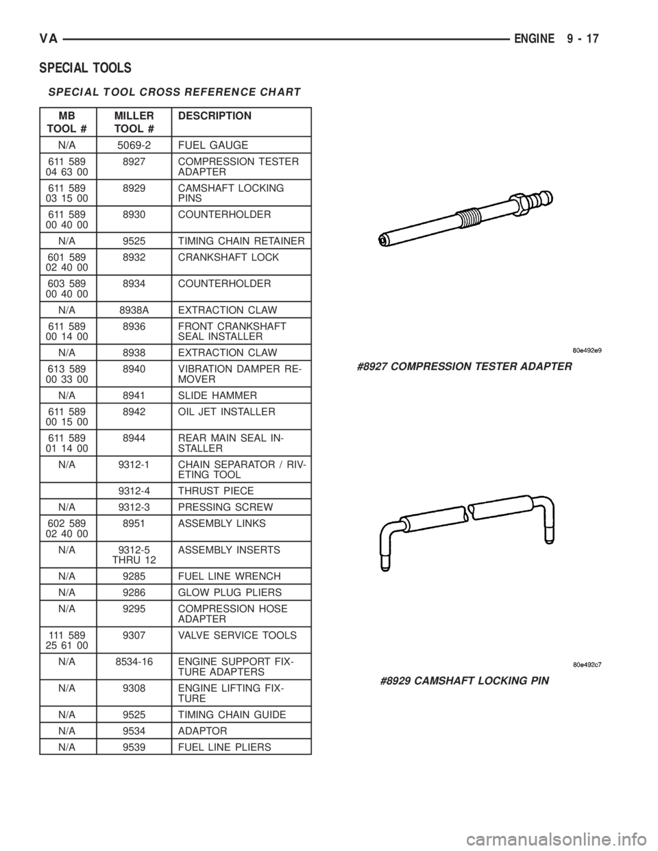
SPECIAL TOOLS
SPECIAL TOOL CROSS REFERENCE CHART
MB
TOOL #MILLER
TOOL #DESCRIPTION
N/A 5069-2 FUEL GAUGE
611 589
04 63 008927 COMPRESSION TESTER
ADAPTER
611 589
03 15 008929 CAMSHAFT LOCKING
PINS
611 589
00 40 008930 COUNTERHOLDER
N/A 9525 TIMING CHAIN RETAINER
601 589
02 40 008932 CRANKSHAFT LOCK
603 589
00 40 008934 COUNTERHOLDER
N/A 8938A EXTRACTION CLAW
611 589
00 14 008936 FRONT CRANKSHAFT
SEAL INSTALLER
N/A 8938 EXTRACTION CLAW
613 589
00 33 008940 VIBRATION DAMPER RE-
MOVER
N/A 8941 SLIDE HAMMER
611 589
00 15 008942 OIL JET INSTALLER
611 589
01 14 008944 REAR MAIN SEAL IN-
STALLER
N/A 9312-1 CHAIN SEPARATOR / RIV-
ETING TOOL
9312-4 THRUST PIECE
N/A 9312-3 PRESSING SCREW
602 589
02 40 008951 ASSEMBLY LINKS
N/A 9312-5
THRU 12ASSEMBLY INSERTS
N/A 9285 FUEL LINE WRENCH
N/A 9286 GLOW PLUG PLIERS
N/A 9295 COMPRESSION HOSE
ADAPTER
111 5 8 9
25 61 009307 VALVE SERVICE TOOLS
N/A 8534-16 ENGINE SUPPORT FIX-
TURE ADAPTERS
N/A 9308 ENGINE LIFTING FIX-
TURE
N/A 9525 TIMING CHAIN GUIDE
N/A 9534 ADAPTOR
N/A 9539 FUEL LINE PLIERS
#8927 COMPRESSION TESTER ADAPTER
#8929 CAMSHAFT LOCKING PIN
VAENGINE 9 - 17
Page 1595 of 2305
#8951 ASSEMBLY LINKS
#9285 FUEL LINE WRENCH
# 9286 GLOW PLUG PLIERS
#9295 COMPRESSION HOSE ADAPTOR
#9525 TIMING CHAIN GUIDE
# 9539 FUEL LINE PLIERS
9 - 20 ENGINEVA