2006 MERCEDES-BENZ SPRINTER wheel size
[x] Cancel search: wheel sizePage 393 of 2305

Symptom:
STEERING ANGLE SENSOR IMPLAUSIBLE WHEEL SPEED
POSSIBLE CAUSES
STEERING ANGLE SENSOR INTERMITTENT DTC
STEERING COMPONENT INSPECTION
STEERING ANGLE SENSOR
TEST ACTION APPLICABILITY
1NOTE: If a system undervoltage or overvoltage DTC is set along with this
DTC, diagnose the system voltage DTC first.
NOTE: Electromagnetic (radio) interference can cause an intermittent
system malfunction by interrupting communication between the sensor
and the CAB.
NOTE: The Steering Angle Sensor is very sensitive to changes due to
alignment problems. The sensor must be recalculated using the DRBIIItif
alignment has been changed by more than 5 degrees.
Turn the ignition on.
With the DRBIIIt, erase DTCs.
Test drive the vehicle.
Using the DRBIIIt, perform the road test procedure.
With the DRBIIIt, read DTCs.
NOTE: If the ESP lamp remains illuminated after the test has completed, a
fault code will be set indicating the cause of the failure.
Does this DTC reset?All
Ye s!Go To 2
No!Go To 3
2NOTE: When the vehicle is in a turn, the ESP compares the Steering Angle
Sensor value and the speed of the inner and outer wheels to determine if the
values are plausible.
Inspect the front end and steering components for damage or misalignment.
Inspect the steering column and Steering Angle Sensor for correct mounting and
installation.
Inspect the tires and wheels to make sure that they are the correct size. All tires must
be the same size.
Inspect the left and right Wheel Speed Sensors to make sure they are connected
correctly, i.e. left harness connected to left sensor, etc.
Were any problems found?All
Ye s!Repair or replace components as necessary in accordance with the
Service Information.
No!Replace the Steering Angle Sensor in accordance with the Service
Information.
72
BRAKES (CAB)
Page 395 of 2305

Symptom:
STEERING ANGLE SENSOR INTERNAL FAULT
POSSIBLE CAUSES
STEERING ANGLE SENSOR INTERMITTENT DTC
STEERING ANGLE SENSOR
TEST ACTION APPLICABILITY
1NOTE: If a system undervoltage or overvoltage DTC is set along with this
DTC, diagnose the system voltage DTC first.
NOTE: Electromagnetic (radio) interference can cause an intermittent
system malfunction by interrupting communication between the sensor
and the CAB.
Turn the ignition on.
With the DRBIIIt, erase DTCs.
Move the Steering Wheel from stop to stop several times.
With the DRBIIIt, perform the road test procedure.
With the DRBIIIt, read DTCs.
NOTE: The Steering Angle Sensor is very sensitive to changes due to
alignment problems. The sensor must be recalculated using the DRBIIItif
alignment has been changed by more than 5 degrees.
Does this DTC reset?All
Ye s!Inspect the Steering Angle Sensor for proper installation. Inspect
the wiring and connectors. Repair as necessary. If no other
problems are found, replace the Steering Angle Sensor in accor-
dance with the Service Information.
No!Go To 2
2 The condition that set this DTC is not present at this time.
Monitor the DRBIIItwhile wiggle testing the related harness and connectors. Look
for any related parameters to change or for the DTC to reset.
Inspect the related harness and connectors.
Look for any chafed, pierced, pinched, or partially broken wires.
Look for broken, bent, pushed out, or corroded terminals.
Inspect the tires and wheels to make sure that they are the correct size. All tires must
be the same size.
Inspect the steering column and Steering Angle Sensor for correct mounting and
installation.
Inspect the front end and steering components for damage or misalignment.
Were any problems found?All
Ye s!Repair as necessary.
No!Test Complete.
74
BRAKES (CAB)
Page 729 of 2305
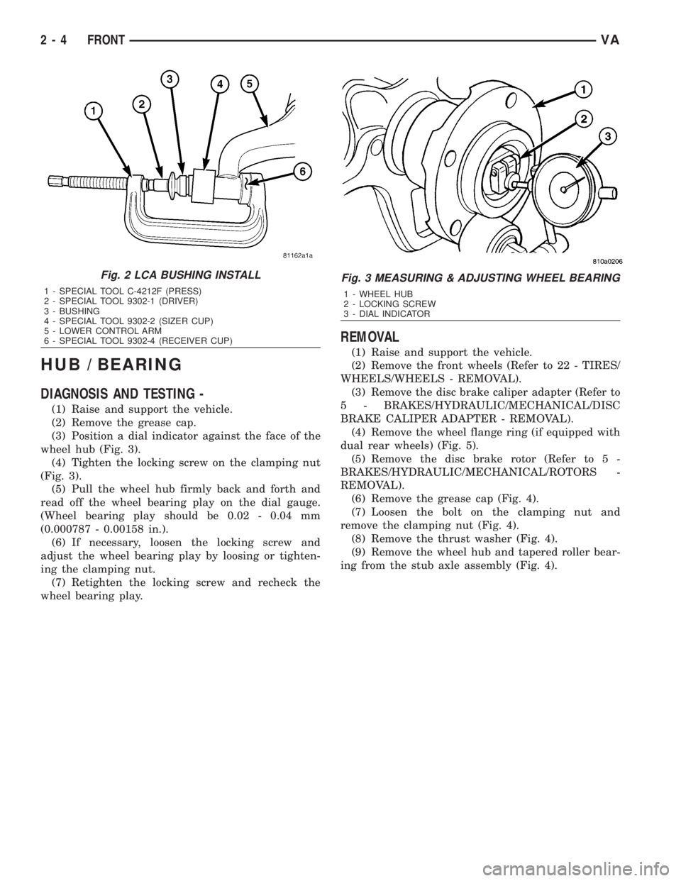
HUB / BEARING
DIAGNOSIS AND TESTING -
(1) Raise and support the vehicle.
(2) Remove the grease cap.
(3) Position a dial indicator against the face of the
wheel hub (Fig. 3).
(4) Tighten the locking screw on the clamping nut
(Fig. 3).
(5) Pull the wheel hub firmly back and forth and
read off the wheel bearing play on the dial gauge.
(Wheel bearing play should be 0.02 - 0.04 mm
(0.000787 - 0.00158 in.).
(6) If necessary, loosen the locking screw and
adjust the wheel bearing play by loosing or tighten-
ing the clamping nut.
(7) Retighten the locking screw and recheck the
wheel bearing play.
REMOVAL
(1) Raise and support the vehicle.
(2) Remove the front wheels (Refer to 22 - TIRES/
WHEELS/WHEELS - REMOVAL).
(3) Remove the disc brake caliper adapter (Refer to
5 - BRAKES/HYDRAULIC/MECHANICAL/DISC
BRAKE CALIPER ADAPTER - REMOVAL).
(4) Remove the wheel flange ring (if equipped with
dual rear wheels) (Fig. 5).
(5) Remove the disc brake rotor (Refer to 5 -
BRAKES/HYDRAULIC/MECHANICAL/ROTORS -
REMOVAL).
(6) Remove the grease cap (Fig. 4).
(7) Loosen the bolt on the clamping nut and
remove the clamping nut (Fig. 4).
(8) Remove the thrust washer (Fig. 4).
(9) Remove the wheel hub and tapered roller bear-
ing from the stub axle assembly (Fig. 4).
Fig. 2 LCA BUSHING INSTALL
1 - SPECIAL TOOL C-4212F (PRESS)
2 - SPECIAL TOOL 9302-1 (DRIVER)
3 - BUSHING
4 - SPECIAL TOOL 9302-2 (SIZER CUP)
5 - LOWER CONTROL ARM
6 - SPECIAL TOOL 9302-4 (RECEIVER CUP)
Fig. 3 MEASURING & ADJUSTING WHEEL BEARING
1 - WHEEL HUB
2 - LOCKING SCREW
3 - DIAL INDICATOR
2 - 4 FRONTVA
Page 733 of 2305

(11) Separate the lower ball joint from the knuckle
using special tool 9282.
(12) Remove the lower control arm nuts and bolts
from the frame.
(13) Remove the lower control arm from the frame
(Fig. 9).
NOTE: To avoid damaging the transverse leaf
spring, cushion the pad on the jack accordingly.
(14) Support the transverse leaf spring in the cen-
ter with a jack.
(15) Remove the left and right spring clamp plates
(Refer to 2 - SUSPENSION/FRONT/SPRING CLAMP
PLATES - REMOVAL) (Fig. 9).
NOTE: The upper spring blocks between the engine
cradle and the spring are color coded, Make sure
not to mix the blocks per sides. The blocks are dif-
ferent in sizes to accommodate the weight of the
vehicle and driver in order for the vehicle to sit
level.
(16) Lower the jack and remove the transverse leaf
spring towards the side.INSTALLATION
NOTE: To avoid damaging the transverse leaf
spring, cushion the pad on the jack accordingly.
NOTE: Hand tighten all bolts until vehicle is on the
ground, unless the bushings may become distorted.
NOTE: The height blocks between the engine cradle
and the spring are color coded, Make sure not to
mix the blocks per sides. The blocks are different in
sizes to accommodate the weight of the vehicle and
driver in order for the vehicle to sit level.
(1) Install the transverse leaf spring in the center
with a jack with all the rubber mounts attached.
(2) Install the lower control arm to the frame (Fig.
9).
(3) Install the knuckle on the lower ball joint.
(4) Raise the lower control arm approximately 10
mm with a jack.
(5) Install both stop plate bolts to the lower control
arm
(6) Install the strut bolts to the steering knuckle.
(7) Reinstall the tie rod to the steering knuckle
(Fig. 9). Tighten to 150 N´m (110 ft. lbs.).
(8) Install the ABS sensor all the way into the
steering knuckle, the sensor will adjust automatically
when the vehicle is moved (Fig. 9).
(9) Install the disc brake caliper adapter (Fig. 9).
Tighten to 170 N´m (125 ft. lbs.).
(10) Install the front wheels.
(11) Lower the vehicle.
(12) Install the spring clamp plates (Fig. 9).
Tighten (M-10 bolts) to 65 N´m (48 ft. lbs.) (M-12
bolts) to 130 N´m (96 ft. lbs.).
(13) Roll the vehicle approximately 1 mm forwards
and the backwards, and rock firmly.
(14) Tighten the nuts on the lower control arm to
the frame to 150 N´m (110 ft. lbs.).
(15) Apply brake to actuate brake pressure.
SPRING CLAMP PLATES
REMOVAL
(1) Raise and support the vehicle.
(2) Install a jack under the lower ball joint and
lower the weight of the vehicle enough to allow a
wrench between the lower control arm and the
bracket tighten the nut.
(3) Remove the front and rear bolts to the spring
clamp plates.
(4) Remove the four inner retaining bolts and
nuts.
Fig. 9 FRONT SPRING
1 - NUT
2 - STRUT
3 - STOP PLATE
4 - STOP PLATE BOLT
5 - CALIPER ADAPTER BOLT
6 - DISC BRAKE CALIPER
7 - OUTER TIE ROD END NUT
8 - ABS SENSOR
9 - SPEED SENSOR
10 - LOWER CONTROL ARM RETAINING NUTS
11 - OUTER TIE ROD END
12 - RUBBER SPRING MOUNT
13 - SHEAR BUSHING
14 - SPRING CLAMP PLATE BOLT
15 - SPRING CLAMP PLATE
16 - LOWER RUBBER SPRING MOUNT
17 - SPRING
18 - STRUT BOLTS
19 - LOWER CONTROL ARM BOLTS
2 - 8 FRONTVA
Page 742 of 2305
WHEEL ALIGNMENT
TABLE OF CONTENTS
page page
WHEEL ALIGNMENT
DESCRIPTION........................17
DIAGNOSIS AND TESTING - PRE-ALIGNMENT
INSPECTION.........................17STANDARD PROCEDURE - TOE
ADJUSTMENT........................18
SPECIFICATIONS.....................19
WHEEL ALIGNMENT
DESCRIPTION
NOTE: Camber and Caster are not adjustable on
this vehicle. (TOE ONLY).
NOTE: Suspension components with rubber/ure-
thane bushings should be tightened with the vehi-
cle at normal ride height. It is important to have the
springs supporting the weight of the vehicle when
the fasteners are torqued. If springs are not at their
normal ride position, vehicle ride comfort could be
affected and premature bushing wear may occur.
Wheel alignment involves the correct positioning of
the wheels in relation to the vehicle. The positioning
is accomplished through suspension and steering
linkage adjustments. An alignment is considered
essential for efficient steering, good directional stabil-
ity and to minimize tire wear. The most important
measurements of an alignment are caster, camber
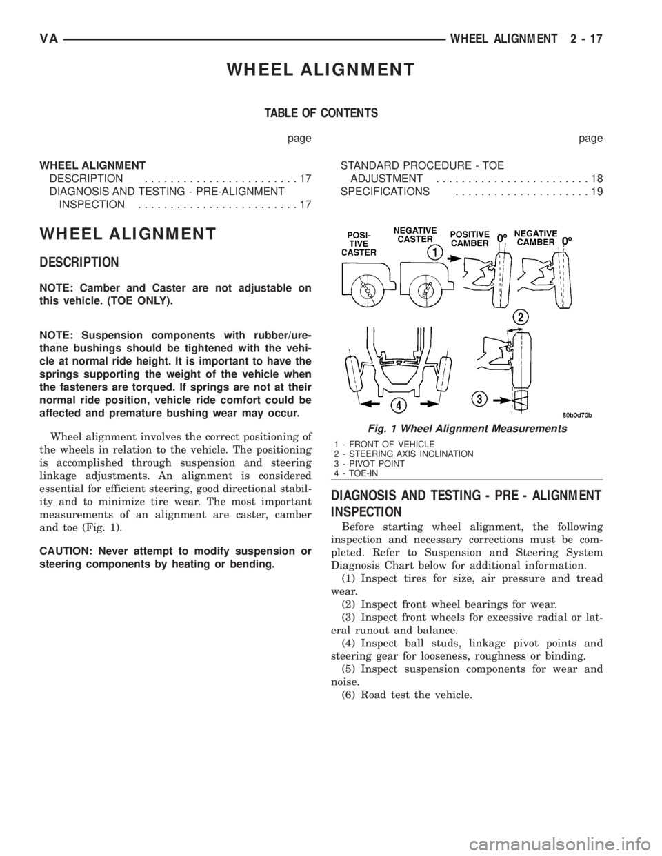
and toe (Fig. 1).
CAUTION: Never attempt to modify suspension or
steering components by heating or bending.
DIAGNOSIS AND TESTING - PRE - ALIGNMENT
INSPECTION
Before starting wheel alignment, the following
inspection and necessary corrections must be com-
pleted. Refer to Suspension and Steering System
Diagnosis Chart below for additional information.
(1) Inspect tires for size, air pressure and tread
wear.
(2) Inspect front wheel bearings for wear.
(3) Inspect front wheels for excessive radial or lat-
eral runout and balance.
(4) Inspect ball studs, linkage pivot points and
steering gear for looseness, roughness or binding.
(5) Inspect suspension components for wear and
noise.
(6) Road test the vehicle.
Fig. 1 Wheel Alignment Measurements
1 - FRONT OF VEHICLE
2 - STEERING AXIS INCLINATION
3 - PIVOT POINT
4 - TOE-IN
VAWHEEL ALIGNMENT 2 - 17
Page 797 of 2305
BRAKE LINES
STANDARD PROCEDURE
STANDARD PROCEDURE - ISO FLARING
A preformed metal brake tube is recommended and
preferred for all repairs. However, double-wall steel
tube can be used for emergency repair when factory
replacement parts are not readily available.
To make a ISO flare use an ISO flaring tool kit.
(1) Cut off damaged tube with Tubing Cutter.
(2) Remove any burrs from the inside of the tube.
(3) Install tube nut on the tube.
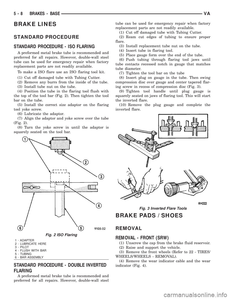
(4) Position the tube in the flaring tool flush with
the top of the tool bar (Fig. 2). Then tighten the tool
bar on the tube.
(5) Install the correct size adaptor on the flaring
tool yoke screw.
(6) Lubricate the adaptor.
(7) Align the adaptor and yoke screw over the tube
(Fig. 2).
(8) Turn the yoke screw in until the adaptor is
squarely seated on the tool bar.
STANDARD PROCEDURE - DOUBLE INVERTED
FLARING
A preformed metal brake tube is recommended and
preferred for all repairs. However, double-wall steeltube can be used for emergency repair when factory
replacement parts are not readily available.
(1) Cut off damaged tube with Tubing Cutter.
(2) Ream cut edges of tubing to ensure proper
flare.
(3) Install replacement tube nut on the tube.
(4) Insert tube in flaring tool.
(5) Place gauge form over the end of the tube.
(6) Push tubing through flaring tool jaws until
tube contacts recessed notch in gauge that matches
tube diameter.
(7) Tighten the tool bar on the tube
(8) Insert plug on gauge in the tube. Then swing
compression disc over gauge and center tapered flar-
ing screw in recess of compression disc (Fig. 3).
(9) Tighten tool handle until plug gauge is
squarely seated on jaws of flaring tool. This will start
the inverted flare.
(10) Remove the plug gauge and complete the
inverted flare.
BRAKE PADS / SHOES
REMOVAL
REMOVAL - FRONT (SRW)
(1) Unscrew the cap from the brake fluid reservoir.
(2) Raise and support the vehicle.
(3) Remove the front wheels (Refer to 22 - TIRES/
WHEELS/WHEELS - REMOVAL).
(4) Remove the wear indicator cable and the wear
indicator (Fig. 4).
Fig. 2 ISO Flaring
1 - ADAPTER
2 - LUBRICATE HERE
3 - PILOT
4 - FLUSH WITH BAR
5 - TUBING
6 - BAR ASSEMBLY
Fig. 3 Inverted Flare Tools
5 - 8 BRAKES - BASEVA
Page 1731 of 2305
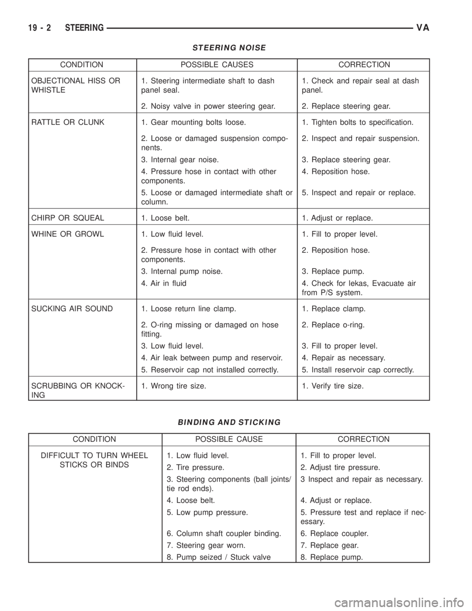
STEERING NOISE
CONDITION POSSIBLE CAUSES CORRECTION
OBJECTIONAL HISS OR
WHISTLE1. Steering intermediate shaft to dash
panel seal.1. Check and repair seal at dash
panel.
2. Noisy valve in power steering gear. 2. Replace steering gear.
RATTLE OR CLUNK 1. Gear mounting bolts loose. 1. Tighten bolts to specification.
2. Loose or damaged suspension compo-
nents.2. Inspect and repair suspension.
3. Internal gear noise. 3. Replace steering gear.
4. Pressure hose in contact with other
components.4. Reposition hose.
5. Loose or damaged intermediate shaft or
column.5. Inspect and repair or replace.
CHIRP OR SQUEAL 1. Loose belt. 1. Adjust or replace.
WHINE OR GROWL 1. Low fluid level. 1. Fill to proper level.
2. Pressure hose in contact with other
components.2. Reposition hose.
3. Internal pump noise. 3. Replace pump.
4. Air in fluid 4. Check for lekas, Evacuate air
from P/S system.
SUCKING AIR SOUND 1. Loose return line clamp. 1. Replace clamp.
2. O-ring missing or damaged on hose
fitting.2. Replace o-ring.
3. Low fluid level. 3. Fill to proper level.
4. Air leak between pump and reservoir. 4. Repair as necessary.
5. Reservoir cap not installed correctly. 5. Install reservoir cap correctly.
SCRUBBING OR KNOCK-
ING1. Wrong tire size. 1. Verify tire size.
BINDING AND STICKING
CONDITION POSSIBLE CAUSE CORRECTION
DIFFICULT TO TURN WHEEL
STICKS OR BINDS1. Low fluid level. 1. Fill to proper level.
2. Tire pressure. 2. Adjust tire pressure.
3. Steering components (ball joints/
tie rod ends).3 Inspect and repair as necessary.
4. Loose belt. 4. Adjust or replace.
5. Low pump pressure. 5. Pressure test and replace if nec-
essary.
6. Column shaft coupler binding. 6. Replace coupler.
7. Steering gear worn. 7. Replace gear.
8. Pump seized / Stuck valve 8. Replace pump.
19 - 2 STEERINGVA
Page 1784 of 2305
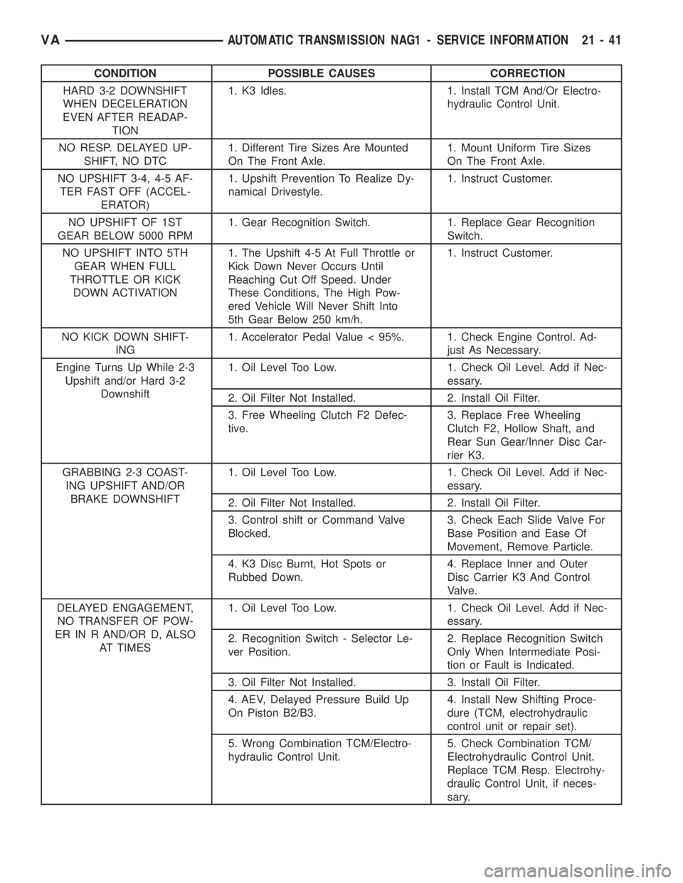
CONDITION POSSIBLE CAUSES CORRECTION
HARD 3-2 DOWNSHIFT
WHEN DECELERATION
EVEN AFTER READAP-
TION1. K3 Idles. 1. Install TCM And/Or Electro-
hydraulic Control Unit.
NO RESP. DELAYED UP-
SHIFT, NO DTC1. Different Tire Sizes Are Mounted
On The Front Axle.1. Mount Uniform Tire Sizes
On The Front Axle.
NO UPSHIFT 3-4, 4-5 AF-
TER FAST OFF (ACCEL-
ERATOR)1. Upshift Prevention To Realize Dy-
namical Drivestyle.1. Instruct Customer.
NO UPSHIFT OF 1ST
GEAR BELOW 5000 RPM1. Gear Recognition Switch. 1. Replace Gear Recognition
Switch.
NO UPSHIFT INTO 5TH
GEAR WHEN FULL
THROTTLE OR KICK
DOWN ACTIVATION1. The Upshift 4-5 At Full Throttle or
Kick Down Never Occurs Until
Reaching Cut Off Speed. Under
These Conditions, The High Pow-
ered Vehicle Will Never Shift Into
5th Gear Below 250 km/h.1. Instruct Customer.
NO KICK DOWN SHIFT-
ING1. Accelerator Pedal Value < 95%. 1. Check Engine Control. Ad-
just As Necessary.
Engine Turns Up While 2-3
Upshift and/or Hard 3-2
Downshift1. Oil Level Too Low. 1. Check Oil Level. Add if Nec-
essary.
2. Oil Filter Not Installed. 2. Install Oil Filter.
3. Free Wheeling Clutch F2 Defec-
tive.3. Replace Free Wheeling
Clutch F2, Hollow Shaft, and
Rear Sun Gear/Inner Disc Car-
rier K3.
GRABBING 2-3 COAST-
ING UPSHIFT AND/OR
BRAKE DOWNSHIFT1. Oil Level Too Low. 1. Check Oil Level. Add if Nec-
essary.
2. Oil Filter Not Installed. 2. Install Oil Filter.
3. Control shift or Command Valve
Blocked.3. Check Each Slide Valve For
Base Position and Ease Of
Movement, Remove Particle.
4. K3 Disc Burnt, Hot Spots or
Rubbed Down.4. Replace Inner and Outer
Disc Carrier K3 And Control
Valve.
DELAYED ENGAGEMENT,
NO TRANSFER OF POW-
ER IN R AND/OR D, ALSO
AT TIMES1. Oil Level Too Low. 1. Check Oil Level. Add if Nec-
essary.
2. Recognition Switch - Selector Le-
ver Position.2. Replace Recognition Switch
Only When Intermediate Posi-
tion or Fault is Indicated.
3. Oil Filter Not Installed. 3. Install Oil Filter.
4. AEV, Delayed Pressure Build Up
On Piston B2/B3.4. Install New Shifting Proce-
dure (TCM, electrohydraulic
control unit or repair set).
5. Wrong Combination TCM/Electro-
hydraulic Control Unit.5. Check Combination TCM/
Electrohydraulic Control Unit.
Replace TCM Resp. Electrohy-
draulic Control Unit, if neces-
sary.
VAAUTOMATIC TRANSMISSION NAG1 - SERVICE INFORMATION 21 - 41