2006 MERCEDES-BENZ SPRINTER brakes
[x] Cancel search: brakesPage 830 of 2305

CONDITION POSSIBLE CAUSES CORRECTION
13. Brakes dragging. 13. Check brakes. (Refer to 5 -
BRAKES/HYDRAULIC/MECHANI-
CAL - DIAGNOSIS AND TESTING)
TEMPERATURE GAUGE READ-
ING INCONSISTENT ( ERRATIC,
CYCLES OR FLUCTUATES)1. Heavy duty cooling system, ex-
tream cold ambient (outside) tem-
perature or heater blower motor in
high position.1. None. System operating norma-
ly.
2. Temperature gauge or gauge
sensor defective.2. Check gauge. (Refer to 8 -
ELECTRICAL/INSTRUMENT CLUS-
TER - DIAGNOSIS AND TESTING)
3. Temporary heavy usage or load. 3. None. Normal condition.
4. Air traped in cooling system. 4. Fill cooling system (Refer to 7 -
COOLING - STANDARD PROCE-
DURE).
5. Water pump 5. Replace water pump.
6. Air leak on suction side of water
pump.6. Check for leak. (Refer to 7 -
COOLING - DIAGNOSIS AND
TESTING)
RADIATOR CAP LEAKING STEAM
AND /OR COOLANT INTO RES-
ERVOIR BOTTLE. (TEMPERA-
TURE GAUGE MAY READ HIGH)1. Radiator cap defective. 1. Replace radiator cap.
2. Radiator neck surface damaged. 2. Replace radiator.
HOSE OR HOSES COLLAPSE
WHEN ENGINE IS COOLING.1. Vacuum created in cooling sys-
tem on engine cool-down is not
being relieved through coolant re-
servior/overflow system.1. Replace radiator cap, check vent
hose between radiator and reser-
voir bottle for blockage also check
reservoir bottle vent for blockage.
NOISY FAN 1. Fan blade(s) loose, damaged. 1. Replace fan blade assembly.
2. Thermal viscous fan drive. 2. None. Normal condition.
3. Fan blades striking surrounding
objects.3. Locate contact point and repair
as necessary.
4. Thermal viscous fan drive bear-
ing.4. Replace viscous fan drive as-
sembly.
5. Obstructed air flow through radi-
ator.5. Remove obstruction.
INADEQUATE AIR CONDITIONER
PERFORMANCE (COOLING SYS-
TEM SUSPECTED)1. Radiator and/or A/C condenser
air flow obstructed.1. Remove obstruction and/or
clean.
2. Thermal viscous fan drive not
working.2. Check fan drive. (Refer to 7 -
COOLING/ENGINE/FAN DRIVE
VISCOUS CLUTCH - DIAGNOSIS
AND TESTING)
3. Air seals around radiator dam-
aged or missing.3. Inspect air seals, repair or re-
place as necessary.
VACOOLING 7 - 3
Page 970 of 2305

MULTI - FUNCTION SWITCH
REMOVAL
WARNING: To avoid personal injury or death, on
vehicles equipped with airbags, disable the supple-
mental restraint system before attempting any
steering wheel, steering column, airbag, seat belt
tensioner, or instrument panel component diagno-
sis or service. Disconnect and isolate the battery
negative (ground) cable, then wait two minutes for
the system capacitor to discharge before perform-
ing further diagnosis or service. This is the only
sure way to disable the supplemental restraint sys-
tem. Failure to take the proper precautions could
result in accidental airbag deployment.
(1) Disconnect and isolate the battery negative
cable.
(2) Remove the fuse block from the underside of
the steering column. (Refer to 8 - ELECTRICAL/
POWER DISTRIBUTION/FUSE BLOCK -
REMOVAL).
(3) Remove the clockspring from the steering col-
umn. (Refer to 8 - ELECTRICAL/RESTRAINTS/
CLOCKSPRING - REMOVAL).
(4) If the vehicle is so equipped, remove the steer-
ing angle sensor from the steering column. (Refer to
5 - BRAKES/ELECTRICAL/STEERING ANGLE
SENSOR - REMOVAL).
(5) Remove the two screws that secure the upper
shroud to the top of the multi-function switch (Fig.
37).
(6) Remove the upper shroud from the top of the
multi-function switch.
(7) Remove the two screws that secure the multi-
function switch to the steering column.(8) Remove the multi-function switch from the
steering column.
(9) Remove the speed control switch from the back
of the multi-function switch. (Refer to 8 - ELECTRI-
CAL/SPEED CONTROL/SWITCH - REMOVAL).
INSTALLATION
WARNING: To avoid personal injury or death, on
vehicles equipped with airbags, disable the supple-
mental restraint system before attempting any
steering wheel, steering column, airbag, seat belt
tensioner, or instrument panel component diagno-
sis or service. Disconnect and isolate the battery
negative (ground) cable, then wait two minutes for
the system capacitor to discharge before perform-
ing further diagnosis or service. This is the only
sure way to disable the supplemental restraint sys-
tem. Failure to take the proper precautions could
result in accidental airbag deployment.
(1) Reinstall the speed control switch onto the
back of the multi-function switch. (Refer to 8 - ELEC-
TRICAL/SPEED CONTROL/SWITCH - INSTALLA-
TION).
(2) Position the multi-function switch onto the
steering column (Fig. 37).
(3) Install and tighten the two screws that secure
the multi-function switch to the steering column.
(4) Position the upper shroud onto the top of the
multi-function switch.
(5) Install and tighten the two screws that secure
the upper shroud to the top of the multi-function
switch.
(6) If the vehicle is so equipped, reinstall the steer-
ing angle sensor onto the steering column. (Refer to 5
- BRAKES/ELECTRICAL/STEERING ANGLE SEN-
SOR - INSTALLATION).
(7) Reinstall the clockspring onto the steering col-
umn. (Refer to 8 - ELECTRICAL/RESTRAINTS/
CLOCKSPRING - INSTALLATION).
(8) Reinstall the fuse block onto the underside of
the steering column. (Refer to 8 - ELECTRICAL/
POWER DISTRIBUTION/FUSE BLOCK - INSTAL-
LATION).
(9) Reconnect the battery negative cable.
PARK BRAKE SWITCH
REMOVAL
(1) Remove the trim cover from the park brake
lever (Fig. 38). (Refer to 5 - BRAKES/PARKING
BRAKE/LEVER - REMOVAL).
Fig. 37 Multi-Function Switch Remove/Install
1 - SCREW (2)
2 - UPPER SHROUD
3 - SWITCH
4 - SCREW (2)
VALAMPS/LIGHTING - EXTERIOR 8L - 21
Page 971 of 2305
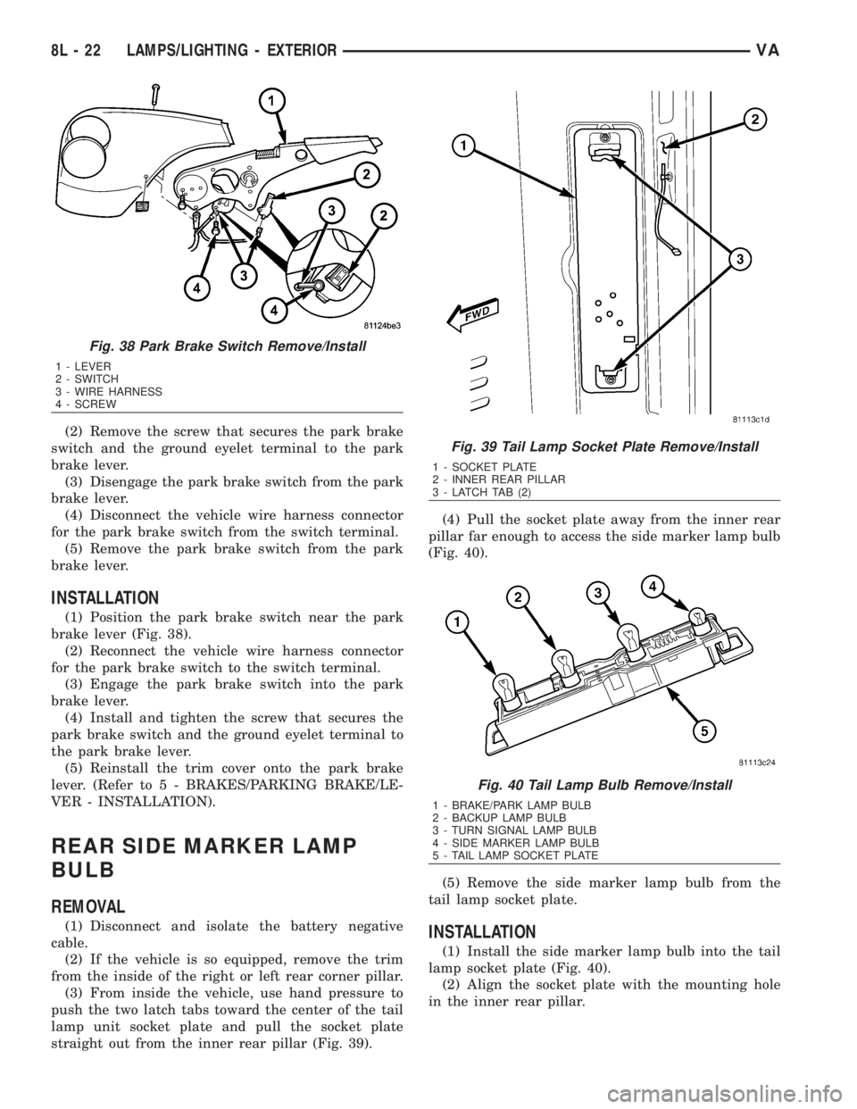
(2) Remove the screw that secures the park brake
switch and the ground eyelet terminal to the park
brake lever.
(3) Disengage the park brake switch from the park
brake lever.
(4) Disconnect the vehicle wire harness connector
for the park brake switch from the switch terminal.
(5) Remove the park brake switch from the park
brake lever.
INSTALLATION
(1) Position the park brake switch near the park
brake lever (Fig. 38).
(2) Reconnect the vehicle wire harness connector
for the park brake switch to the switch terminal.
(3) Engage the park brake switch into the park
brake lever.
(4) Install and tighten the screw that secures the
park brake switch and the ground eyelet terminal to
the park brake lever.
(5) Reinstall the trim cover onto the park brake
lever. (Refer to 5 - BRAKES/PARKING BRAKE/LE-
VER - INSTALLATION).
REAR SIDE MARKER LAMP
BULB
REMOVAL
(1) Disconnect and isolate the battery negative
cable.
(2) If the vehicle is so equipped, remove the trim
from the inside of the right or left rear corner pillar.
(3) From inside the vehicle, use hand pressure to
push the two latch tabs toward the center of the tail
lamp unit socket plate and pull the socket plate
straight out from the inner rear pillar (Fig. 39).(4) Pull the socket plate away from the inner rear
pillar far enough to access the side marker lamp bulb
(Fig. 40).
(5) Remove the side marker lamp bulb from the
tail lamp socket plate.INSTALLATION
(1) Install the side marker lamp bulb into the tail
lamp socket plate (Fig. 40).
(2) Align the socket plate with the mounting hole
in the inner rear pillar.
Fig. 38 Park Brake Switch Remove/Install
1 - LEVER
2 - SWITCH
3 - WIRE HARNESS
4 - SCREW
Fig. 39 Tail Lamp Socket Plate Remove/Install
1 - SOCKET PLATE
2 - INNER REAR PILLAR
3 - LATCH TAB (2)
Fig. 40 Tail Lamp Bulb Remove/Install
1 - BRAKE/PARK LAMP BULB
2 - BACKUP LAMP BULB
3 - TURN SIGNAL LAMP BULB
4 - SIDE MARKER LAMP BULB
5 - TAIL LAMP SOCKET PLATE
8L - 22 LAMPS/LIGHTING - EXTERIORVA
Page 1035 of 2305
OPERATION
When speed control operation is selected by the
speed control switch, the ECM (Engine Control Mod-
ule) allows a set speed to be stored in its RAM for
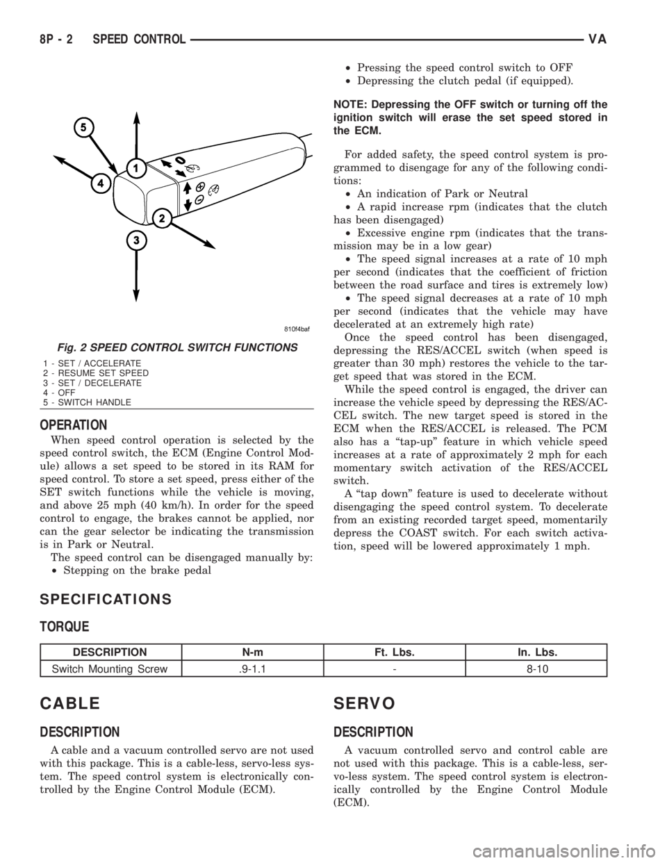
speed control. To store a set speed, press either of the
SET switch functions while the vehicle is moving,
and above 25 mph (40 km/h). In order for the speed
control to engage, the brakes cannot be applied, nor
can the gear selector be indicating the transmission
is in Park or Neutral.
The speed control can be disengaged manually by:
²Stepping on the brake pedal²Pressing the speed control switch to OFF
²Depressing the clutch pedal (if equipped).
NOTE: Depressing the OFF switch or turning off the
ignition switch will erase the set speed stored in
the ECM.
For added safety, the speed control system is pro-
grammed to disengage for any of the following condi-
tions:
²An indication of Park or Neutral
²A rapid increase rpm (indicates that the clutch
has been disengaged)
²Excessive engine rpm (indicates that the trans-
mission may be in a low gear)
²The speed signal increases at a rate of 10 mph
per second (indicates that the coefficient of friction
between the road surface and tires is extremely low)
²The speed signal decreases at a rate of 10 mph
per second (indicates that the vehicle may have
decelerated at an extremely high rate)
Once the speed control has been disengaged,
depressing the RES/ACCEL switch (when speed is
greater than 30 mph) restores the vehicle to the tar-
get speed that was stored in the ECM.
While the speed control is engaged, the driver can
increase the vehicle speed by depressing the RES/AC-
CEL switch. The new target speed is stored in the
ECM when the RES/ACCEL is released. The PCM
also has a ªtap-upº feature in which vehicle speed
increases at a rate of approximately 2 mph for each
momentary switch activation of the RES/ACCEL
switch.
A ªtap downº feature is used to decelerate without
disengaging the speed control system. To decelerate
from an existing recorded target speed, momentarily
depress the COAST switch. For each switch activa-
tion, speed will be lowered approximately 1 mph.
SPECIFICATIONS
TORQUE
DESCRIPTION N-m Ft. Lbs. In. Lbs.
Switch Mounting Screw .9-1.1 - 8-10
CABLE
DESCRIPTION
A cable and a vacuum controlled servo are not used
with this package. This is a cable-less, servo-less sys-
tem. The speed control system is electronically con-
trolled by the Engine Control Module (ECM).
SERVO
DESCRIPTION
A vacuum controlled servo and control cable are
not used with this package. This is a cable-less, ser-
vo-less system. The speed control system is electron-
ically controlled by the Engine Control Module
(ECM).
Fig. 2 SPEED CONTROL SWITCH FUNCTIONS
1 - SET / ACCELERATE
2 - RESUME SET SPEED
3 - SET / DECELERATE
4 - OFF
5 - SWITCH HANDLE
8P - 2 SPEED CONTROLVA
Page 1080 of 2305
WIRING
TABLE OF CONTENTS
page page
WIRING DIAGRAM INFORMATION....... 8W-01-1
COMPONENT INDEX.................. 8W-02-1
POWER DISTRIBUTION............... 8W-10-1
FUSE BLOCK........................ 8W-11-1
GROUND DISTRIBUTION.............. 8W-15-1
BUS COMMUNICATIONS.............. 8W-18-1
CHARGING SYSTEM.................. 8W-20-1
STARTING SYSTEM.................. 8W-21-1
FUEL/IGNITION SYSTEM.............. 8W-30-1
TRANSMISSION CONTROL SYSTEM..... 8W-31-1
VEHICLE SPEED CONTROL............ 8W-33-1
ANTILOCK BRAKES................... 8W-35-1
VEHICLE THEFT SECURITY SYSTEM..... 8W-39-1
INSTRUMENT CLUSTER............... 8W-40-1
HORN/CIGAR LIGHTER................ 8W-41-1
AIR CONDITIONING-HEATER........... 8W-42-1
AIRBAG SYSTEM.................... 8W-43-1
INTERIOR LIGHTING.................. 8W-44-1CENTRAL TIMER MODULE............. 8W-45-1
AUDIO SYSTEM..................... 8W-47-1
REAR WINDOW DEFOGGER............ 8W-48-1
FRONT LIGHTING.................... 8W-50-1
REAR LIGHTING..................... 8W-51-1
TURN SIGNALS...................... 8W-52-1
WIPERS............................ 8W-53-1
TRAILER TOW....................... 8W-54-1
NAVIGATION/TELECOMMUNICATIONS.... 8W-55-1
POWER WINDOWS................... 8W-60-1
POWER DOOR LOCKS................ 8W-61-1
POWER MIRRORS................... 8W-62-1
POWER SEATS...................... 8W-63-1
SPLICE INFORMATION................ 8W-70-1
CONNECTOR PIN-OUTS............... 8W-80-1
CONNECTOR/GROUND/SPLICE
LOCATION........................ 8W-91-1
POWER DISTRIBUTION............... 8W-97-1 VAWIRING 8W - 1
Page 1254 of 2305
8W-35 ANTILOCK BRAKES
Component Page
Automatic Temperature Control Module . . 8W-35-2
Brake Fluid Level Switch.............. 8W-35-7
Brake Lamp Switch................ 8W-35-3, 4
Brake Lamp Switch 4 Pole............ 8W-35-10
Brake Pressure Sensor................ 8W-35-9
Brake Wear Sensor-Left Front.......... 8W-35-8
Brake Wear Sensor-Left Rear........... 8W-35-8
Brake Wear Sensor-Right Front......... 8W-35-8
Brake Wear Sensor-Right Rear......... 8W-35-8
Center High Mounted Stop Lamp..... 8W-35-3, 10
Controller Antilock Brake . 8W-35-2, 3, 4, 5, 6, 9, 10
Data Link Connector................. 8W-35-5
Daytime Running Lamps Relay......... 8W-35-2
Fuse 2............................ 8W-35-5
Fuse 3............................ 8W-35-5
Fuse 5.......................... 8W-35-3, 10
Fuse 6............................ 8W-35-5
Fuse 7............................ 8W-35-5
Fuse 9............................ 8W-35-5
Fuse Block No. 1.................. 8W-35-3, 10
Fuse/Relay Block.................... 8W-35-5
G100.............................. 8W-35-4Component Page
G200.......................... 8W-35-4, 7, 8
G202.............................. 8W-35-7
G203.............................. 8W-35-2
G300.............................. 8W-35-8
G302.............................. 8W-35-4
Instrument Cluster................. 8W-35-7, 8
Lateral Acceleration Sensor............ 8W-35-9
Optional Equipment Relay............. 8W-35-5
Parking Brake Switch................ 8W-35-7
Power Distribution Center............. 8W-35-5
Relay Block........................ 8W-35-5
Shifter Assembly.................... 8W-35-3
Steering Angle Sensor................ 8W-35-4
TCS Switch........................ 8W-35-2
Tail Lamp Assembly-Left........... 8W-35-3, 10
Tail Lamp Assembly-Right.......... 8W-35-3, 10
Trailer Tow Control Module......... 8W-35-3, 10
Wheel Speed Sensor-Left Front......... 8W-35-6
Wheel Speed Sensor-Left Rear.......... 8W-35-6
Wheel Speed Sensor-Right Front........ 8W-35-6
Wheel Speed Sensor-Right Rear......... 8W-35-6
VA8W-35 ANTILOCK BRAKES 8W - 35 - 1
Page 1497 of 2305
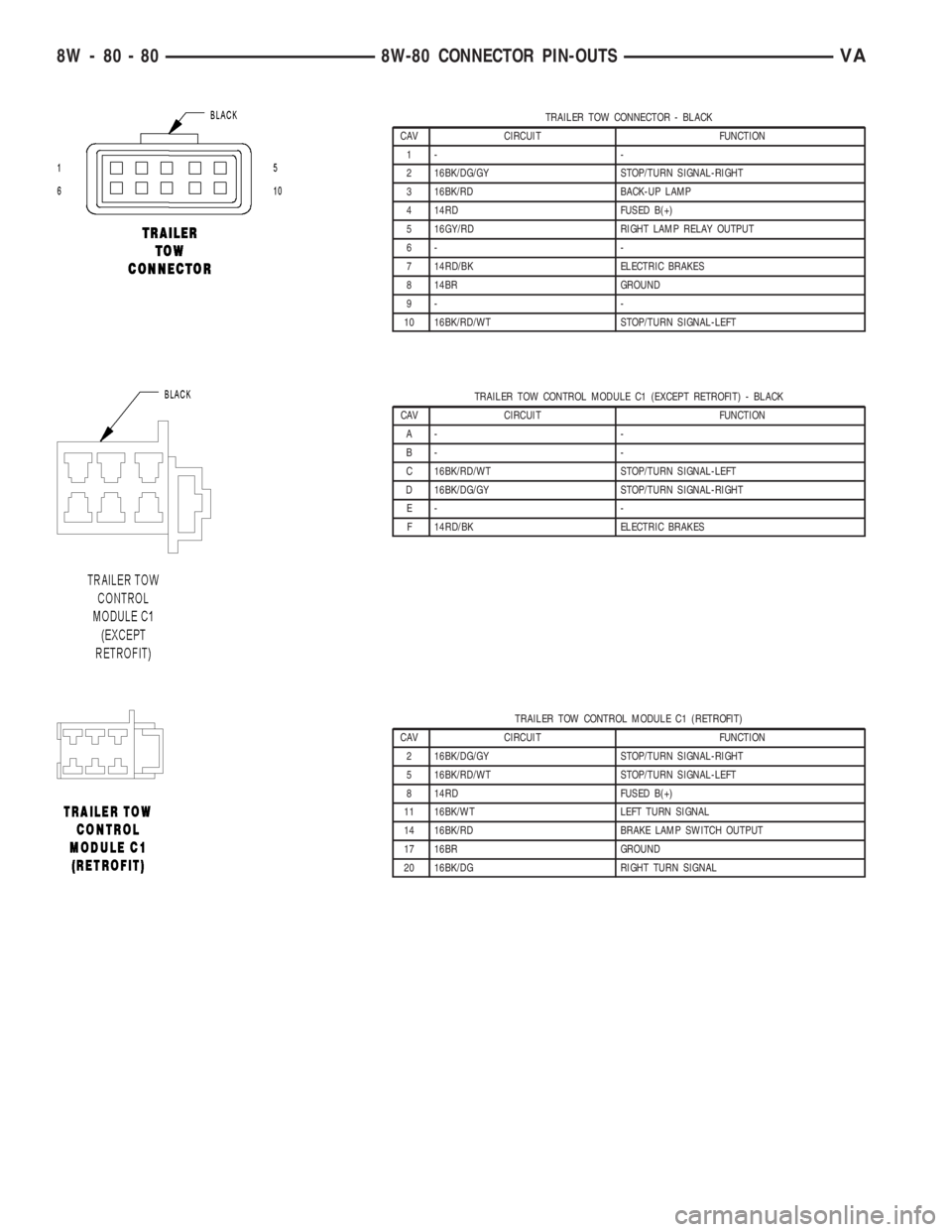
TRAILER TOW CONNECTOR - BLACK
CAV CIRCUIT FUNCTION
1- -
2 16BK/DG/GY STOP/TURN SIGNAL-RIGHT
3 16BK/RD BACK-UP LAMP
4 14RD FUSED B(+)
5 16GY/RD RIGHT LAMP RELAY OUTPUT
6- -
7 14RD/BK ELECTRIC BRAKES
8 14BR GROUND
9- -
10 16BK/RD/WT STOP/TURN SIGNAL-LEFT
TRAILER TOW CONTROL MODULE C1 (EXCEPT RETROFIT) - BLACK
CAV CIRCUIT FUNCTION
A- -
B- -
C 16BK/RD/WT STOP/TURN SIGNAL-LEFT
D 16BK/DG/GY STOP/TURN SIGNAL-RIGHT
E- -
F 14RD/BK ELECTRIC BRAKES
TRAILER TOW CONTROL MODULE C1 (RETROFIT)
CAV CIRCUIT FUNCTION
2 16BK/DG/GY STOP/TURN SIGNAL-RIGHT
5 16BK/RD/WT STOP/TURN SIGNAL-LEFT
8 14RD FUSED B(+)
11 16BK/WT LEFT TURN SIGNAL
14 16BK/RD BRAKE LAMP SWITCH OUTPUT
17 16BR GROUND
20 16BK/DG RIGHT TURN SIGNAL
8W - 80 - 80 8W-80 CONNECTOR PIN-OUTSVA
Page 1675 of 2305
SPECIFICATIONS - TORQUE
TORQUE SPECIFICATIONS
DESCRIPTION N´m Ft. Lbs. In. Lbs.
Brake line nuts 14 10 Ð
Brake pads wear
indicator caliper
bolt10 7 89
Engine cradle bolts 125 92 Ð
Engine mount bolt
to engine bracket83 61 Ð
Engine mount nuts
to engine cradle45 33 Ð
Power steering line
nuts37 27 Ð
Steering gear
mounting bolts -
1st stage25 18 Ð
Steering Gear
mounting bolts -
2nd stage45 33 Ð
Steering Gear
mounting bolts -
3rd stage90ÉÐÐ
Steering gear u-
joint bolt24 18 Ð
Sway bar bushing
bolts30 22 Ð
Trailer hitch angle
bracket bolts/nuts50*
See
Warning37*
See
WarningÐ
Trailer hitch frame
bolts11 0 8 1 Ð
Transmission cross-
member nuts45 33 Ð
Transmission
mount bolts/nuts45 33 Ð
WARNING: Microencapsulated bolts and self-lock-
ing nuts may only be used once. If you use
microencapsulated bolt or self-locking nuts more
than once, the self-locking function is rendered
useless. The trailer hitch may become detached
from the vehicle, possibly resulting in a serious risk
of injury and/or damage to property, including dam-
age to the vehicle.
ENGINE CRADLE CROSSMEM-
BER
REMOVAL
(1) Install engine support tool 8534 or equivalent.
(2) Raise and support the vehicle. (Refer to
LUBRICATION & MAINTENANCE/HOISTING -
STANDARD PROCEDURE)
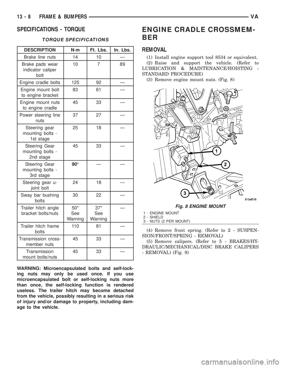
(3) Remove engine mount nuts. (Fig. 8)
(4) Remove front spring. (Refer to 2 - SUSPEN-
SION/FRONT/SPRING - REMOVAL)
(5) Remove calipers. (Refer to 5 - BRAKES/HY-
DRAULIC/MECHANICAL/DISC BRAKE CALIPERS
- REMOVAL) (Fig. 9)
Fig. 8 ENGINE MOUNT
1 - ENGINE MOUNT
2 - SHIELD
3 - NUTS (2 PER MOUNT)
13 - 8 FRAME & BUMPERSVA