2006 MERCEDES-BENZ SPRINTER fuse diagram
[x] Cancel search: fuse diagramPage 12 of 2305

TABLE OF CONTENTS - Continued
FUSES (FUSE BLOCK NO. 2)............................................274
FUSES (FUSE BLOCK NO. 3)............................................276
FUSES (FUSE/RELAY BLOCK)...........................................278
HOOD AJAR SWITCH - BLACK...........................................278
HORN (VTSS).........................................................278
IGNITION LOCK SWITCH - BLACK........................................278
INSTRUMENT CLUSTER C1.............................................279
INSTRUMENT CLUSTER C2 - WHITE.....................................279
INTRUSION SENSOR NO. 1 - BLACK.....................................279
INTRUSION SENSOR NO. 2 - BLACK.....................................279
INTRUSION SENSOR NO. 3 - BLACK.....................................280
MASTER DOOR LOCK SWITCH..........................................280
PANIC ALARM SWITCH - BLACK.........................................280
FUSES (PDC).........................................................281
RADIO C1 - BLACK....................................................282
RADIO C2............................................................282
RECIRCULATED AIR SOLENOID VALVE...................................282
REFRIGERANT PRESSURE SENSOR.....................................282
A/C AUXILIARY FAN RELAY (RELAY BLOCK)...............................284
CIRCULATION PUMP RELAY-CABIN HEATER MODULE (RELAY BLOCK).......284
D+ RELAY NO. 2 (RELAY BLOCK)........................................284
FAN STAGE 1 RELAY (RELAY BLOCK)....................................284
OPTIONAL EQUIPMENT RELAY (RELAY BLOCK)...........................284
REMOTE KEYLESS ENTRY ANTENNA....................................284
SEAT BELT SWITCH...................................................284
SEAT BELT TENSIONER-DRIVER - YELLOW...............................285
SEAT BELT TENSIONER-PASSENGER - YELLOW...........................285
SECURITY SYSTEM MODULE C1 - BROWN...............................285
SECURITY SYSTEM MODULE C2 - LT. GREEN.............................286
SENTRY KEY REMOTE ENTRY MODULE (SKREEM)........................286
SHIFTER ASSEMBLY - BLACK...........................................286
SIREN - BLACK.......................................................286
STEERING ANGLE SENSOR............................................287
TOWING/INTRUSION SENSOR ON/OFF SWITCH...........................287
TRANSMISSION CONTROL MODULE C1 - BLACK..........................287
TRANSMISSION CONTROL MODULE C2 - BLACK..........................288
WATER CYCLE VALVE..................................................288
WINDOW DEFOGGER-LEFT REAR.......................................288
WINDOW DEFOGGER-RIGHT REAR......................................288
10.0 SCHEMATIC DIAGRAMS................................................289
10.1AIRBAG SYSTEM.................................................289
10.2COMMUNICATION................................................290
10.2.1COMMUNICATION K-LINES................................290
10.2.2CAN BUS NETWORK......................................291
10.3HEATING & A/C...................................................292
10.3.1AUTOMATIC TEMPERATURE CONTROL (ATC)................292
10.3.2CABIN HEATER MODULE (CHM)............................293
10.3.3HEATER BOOSTER MODULE (HBM).........................294
10.4INSTRUMENT CLUSTER...........................................295
vii
Page 159 of 2305

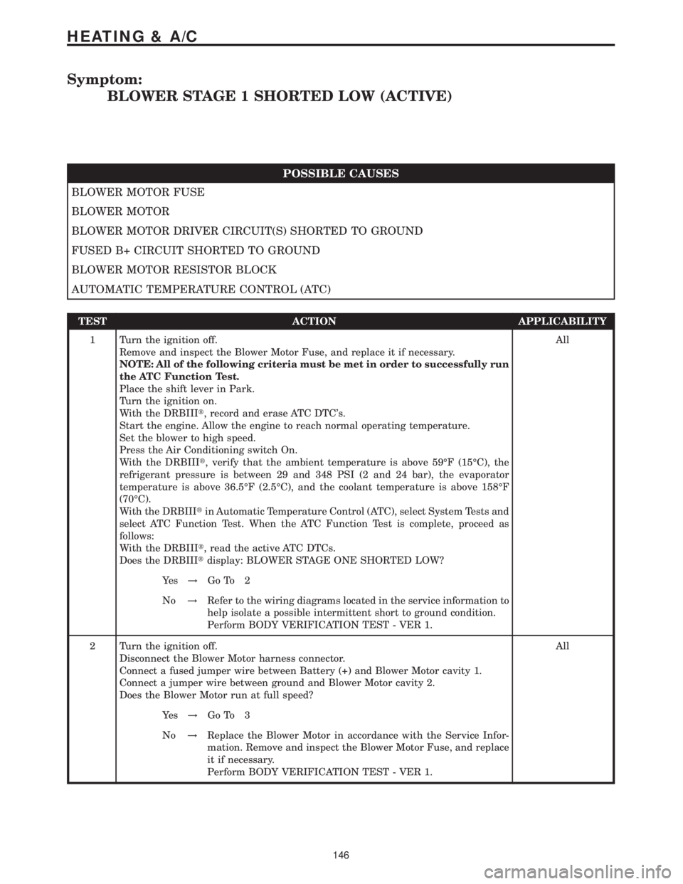
Symptom:
BLOWER STAGE 1 SHORTED LOW (ACTIVE)
POSSIBLE CAUSES
BLOWER MOTOR FUSE
BLOWER MOTOR
BLOWER MOTOR DRIVER CIRCUIT(S) SHORTED TO GROUND
FUSED B+ CIRCUIT SHORTED TO GROUND
BLOWER MOTOR RESISTOR BLOCK
AUTOMATIC TEMPERATURE CONTROL (ATC)
TEST ACTION APPLICABILITY
1 Turn the ignition off.
Remove and inspect the Blower Motor Fuse, and replace it if necessary.
NOTE: All of the following criteria must be met in order to successfully run
the ATC Function Test.
Place the shift lever in Park.
Turn the ignition on.
With the DRBIIIt, record and erase ATC DTC's.
Start the engine. Allow the engine to reach normal operating temperature.
Set the blower to high speed.
Press the Air Conditioning switch On.
With the DRBIIIt, verify that the ambient temperature is above 59ÉF (15ÉC), the
refrigerant pressure is between 29 and 348 PSI (2 and 24 bar), the evaporator
temperature is above 36.5ÉF (2.5ÉC), and the coolant temperature is above 158ÉF
(70ÉC).
With the DRBIIItin Automatic Temperature Control (ATC), select System Tests and
select ATC Function Test. When the ATC Function Test is complete, proceed as
follows:
With the DRBIIIt, read the active ATC DTCs.
Does the DRBIIItdisplay: BLOWER STAGE ONE SHORTED LOW?All
Ye s!Go To 2
No!Refer to the wiring diagrams located in the service information to
help isolate a possible intermittent short to ground condition.
Perform BODY VERIFICATION TEST - VER 1.
2 Turn the ignition off.
Disconnect the Blower Motor harness connector.
Connect a fused jumper wire between Battery (+) and Blower Motor cavity 1.
Connect a jumper wire between ground and Blower Motor cavity 2.
Does the Blower Motor run at full speed?All
Ye s!Go To 3
No!Replace the Blower Motor in accordance with the Service Infor-
mation. Remove and inspect the Blower Motor Fuse, and replace
it if necessary.
Perform BODY VERIFICATION TEST - VER 1.
146
HEATING & A/C
Page 233 of 2305

Symptom:
INTRUSION SENSOR 1 CIRCUIT OPEN/SHORT TO GROUND
When Monitored and Set Condition:
INTRUSION SENSOR 1 CIRCUIT OPEN/SHORT TO GROUND
When Monitored: Whenever the battery voltage is above 10.0 volts and the Security
System Module is connected.
Set Condition: The Security System Module detects the incorrect voltage on the Intrusion
Sensor circuit.
POSSIBLE CAUSES
DTC PRESENT
FUSE 2 IN FUSE BLOCK 3
FUSED B(+) WIRE OPEN
GROUND CIRCUIT OPEN
INTRUSION SENSOR 1 SIGNAL SHORTED
INTRUSION SENSOR 1 SIGNAL CIRCUIT OPEN
INTRUSION SENSOR INTERFACE WIRE SHORTED
INTRUSION SENSOR INTERFACE WIRE OPEN
INTRUSION SENSOR
TEST ACTION APPLICABILITY
1 With the DRBIIIt, record and erase DTC's.
Remove the ignition key.
Close and lock all doors and set the Vehicle Theft Security System.
Wait 1 minute.
Disarm the Vehicle Theft System.
With the DRBIIIt, read DTC's.
Does the DRBIIItdisplay the same DTC?All
Ye s!Go To 2
No!Using the wiring diagram/schematic as a guide, inspect the
wiring and connectors for an intermittent condition.
Perform BODY VERIFICATION TEST - VER 1.
2 Check Fuse 2 in Fuse Block 3.
Is the fuse open?All
Ye s!Check for a short to ground and replace the fuse.
Perform BODY VERIFICATION TEST - VER 1.
No!Go To 3
220
VEHICLE THEFT/SECURITY
Page 236 of 2305

Symptom:
INTRUSION SENSOR 2 CIRCUIT OPEN/SHORT TO GROUND
When Monitored and Set Condition:
INTRUSION SENSOR 2 CIRCUIT OPEN/SHORT TO GROUND
When Monitored: Whenever the battery voltage is above 10.0 volts and the Security
System Module is connected.
Set Condition: The Security System Module detects the incorrect voltage on the Intrusion
Sensor circuit.
POSSIBLE CAUSES
DTC PRESENT
FUSE 2 IN FUSE BLOCK 3
FUSED B(+) WIRE OPEN
GROUND CIRCUIT OPEN
INTRUSION SENSOR 2 SIGNAL SHORTED
INTRUSION SENSOR 2 SIGNAL CIRCUIT OPEN
INTRUSION SENSOR INTERFACE WIRE SHORTED
INTRUSION SENSOR INTERFACE WIRE OPEN
INTRUSION SENSOR
TEST ACTION APPLICABILITY
1 With the DRBIIIt, record and erase DTC's.
Remove the ignition key.
Close and lock all doors and set the Vehicle Theft Security System.
Wait 1 minute.
Disarm the Vehicle Theft System.
With the DRBIIIt, read DTC's.
Does the DRBIIItdisplay the same DTC?All
Ye s!Go To 2
No!Using the wiring diagram/schematic as a guide, inspect the
wiring and connectors for an intermittent condition.
Perform BODY VERIFICATION TEST - VER 1.
2 Check Fuse 2 in Fuse Block 3.
Is the fuse open?All
Ye s!Check for a short to ground and replace the fuse.
Perform BODY VERIFICATION TEST - VER 1.
No!Go To 3
223
VEHICLE THEFT/SECURITY
Page 239 of 2305

Symptom:
INTRUSION SENSOR 3 CIRCUIT OPEN/SHORT TO GROUND
When Monitored and Set Condition:
INTRUSION SENSOR 3 CIRCUIT OPEN/SHORT TO GROUND
When Monitored: Whenever the battery voltage is above 10.0 volts and the Security
System Module is connected.
Set Condition: The Security System Module detects the incorrect voltage on the Intrusion
Sensor circuit.
POSSIBLE CAUSES
DTC PRESENT
FUSE 2 IN FUSE BLOCK 3
FUSED B(+) WIRE OPEN
GROUND CIRCUIT OPEN
INTRUSION SENSOR 3 SIGNAL SHORTED
INTRUSION SENSOR 3 SIGNAL CIRCUIT OPEN
INTRUSION SENSOR INTERFACE WIRE SHORTED
INTRUSION SENSOR INTERFACE WIRE OPEN
INTRUSION SENSOR
TEST ACTION APPLICABILITY
1 With the DRBIIIt, record and erase DTC's.
Remove the ignition key.
Close and lock all doors and set the Vehicle Theft Security System.
Wait 1 minute.
Disarm the Vehicle Theft System.
With the DRBIIIt, read DTC's.
Does the DRBIIItdisplay the same DTC?All
Ye s!Go To 2
No!Using the wiring diagram/schematic as a guide, inspect the
wiring and connectors for an intermittent condition.
Perform BODY VERIFICATION TEST - VER 1.
2 Check Fuse 2 in Fuse Block 3.
Is the fuse open?All
Ye s!Check for a short to ground and replace the fuse.
Perform BODY VERIFICATION TEST - VER 1.
No!Go To 3
226
VEHICLE THEFT/SECURITY
Page 248 of 2305

Symptom:
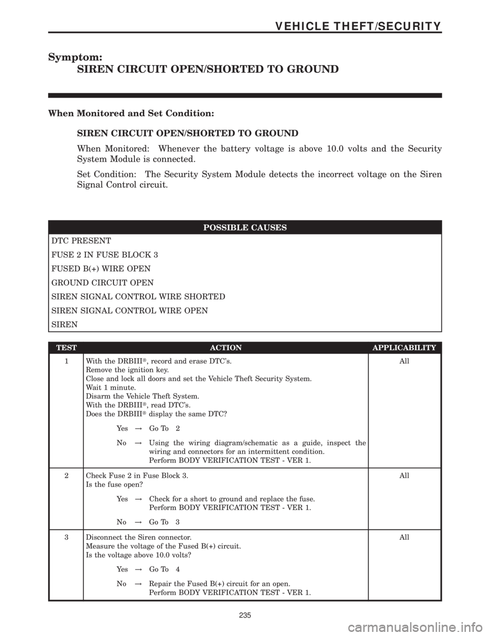
SIREN CIRCUIT OPEN/SHORTED TO GROUND
When Monitored and Set Condition:
SIREN CIRCUIT OPEN/SHORTED TO GROUND
When Monitored: Whenever the battery voltage is above 10.0 volts and the Security
System Module is connected.
Set Condition: The Security System Module detects the incorrect voltage on the Siren
Signal Control circuit.
POSSIBLE CAUSES
DTC PRESENT
FUSE 2 IN FUSE BLOCK 3
FUSED B(+) WIRE OPEN
GROUND CIRCUIT OPEN
SIREN SIGNAL CONTROL WIRE SHORTED
SIREN SIGNAL CONTROL WIRE OPEN
SIREN
TEST ACTION APPLICABILITY
1 With the DRBIIIt, record and erase DTC's.
Remove the ignition key.
Close and lock all doors and set the Vehicle Theft Security System.
Wait 1 minute.
Disarm the Vehicle Theft System.
With the DRBIIIt, read DTC's.
Does the DRBIIItdisplay the same DTC?All
Ye s!Go To 2
No!Using the wiring diagram/schematic as a guide, inspect the
wiring and connectors for an intermittent condition.
Perform BODY VERIFICATION TEST - VER 1.
2 Check Fuse 2 in Fuse Block 3.
Is the fuse open?All
Ye s!Check for a short to ground and replace the fuse.
Perform BODY VERIFICATION TEST - VER 1.
No!Go To 3
3 Disconnect the Siren connector.
Measure the voltage of the Fused B(+) circuit.
Is the voltage above 10.0 volts?All
Ye s!Go To 4
No!Repair the Fused B(+) circuit for an open.
Perform BODY VERIFICATION TEST - VER 1.
235
VEHICLE THEFT/SECURITY
Page 422 of 2305

TABLE OF CONTENTS - Continued
KICK DOWN SWITCH - BLACK...........................................271
MASS AIR FLOW SENSOR - BLACK......................................271
OXYGEN SENSOR (OBD)...............................................271
FUSED IGNITION SWITCH RUN-START RELAY (RELAY BLOCK)..............273
SPEED CONTROL SWITCH.............................................273
WATER IN FUEL SENSOR - BLACK.......................................273
10.0 SCHEMATIC DIAGRAMS................................................275
10.1ENGINE CONTROL MODULE.......................................275
10.2ENGINE CONTROL MODULE.......................................276
11.0 CHARTS AND GRAPHS................................................277
xi
Page 660 of 2305

TEST ACTION APPLICABILITY
8 Turn the ignition off.
Remove and inspect Fuse #16 from Fuse Block No.1
Is the fuse open?All
Ye s!Go To 9
No!Go To 11
9 Turn the ignition off.
Disconnect the ECM harness connectors.
Install a good fuse in place of Fuse #16 in Fuse Block No.1
Connect a jumper wire between ground and the Engine Control Relay Control circuit
in ECM C2 harness connector cavity 44.
Remove and inspect Fuse #16 from Fuse Block No.1.
Is the fuse open?All
Ye s!Repair the Engine Control Relay Output circuit for a short to
ground.
Perform ROAD TEST VERIFICATION - VER-2.
No!Go To 10
10 The Fuel Injectors, Crankcase Heater, Water In Fuel Sensor and related circuits can
cause Fuse #16 in Fuse Block No.1 to open. Use the Service Information Wiring
Diagrams and check these circuits/components for shorted circuits.
Were any problems found.All
Ye s!Repair or replace shorted circuit/component as necessary.
Perform ROAD TEST VERIFICATION - VER-2.
No!Replace and program the ECM in accordance with the Service
Information.
Perform ROAD TEST VERIFICATION - VER-2.
11 Turn the ignition off.
Disconnect the ECM harness connectors.
Connect a jumper wire between ground and the Engine Control Relay Control circuit
in ECM C2 harness connector cavity 44.
Turn the ignition on.
Using a 12-volt test light connected to ground, check the Fused Engine Control Relay
Output circuits at the ECM C2 harness connector cavities 1, 3 and 5.
Choose the appropriate result.All
Test light is on for all circuits.
Test Complete.
Test light is on for 1 or 2 circuits
Repair the Engine Control Relay Output circuit(s) for an open.
Perform ROAD TEST VERIFICATION - VER-2.
Light off for all circuits.
Go To 12
237
DRIVEABILITY - DIESEL
*CHECKING THE POWER AND GROUNDS ÐContinued