Page 256 of 561
255 Controls in detail
Power tilt/sliding sunroof*
�Power tilt/sliding sunroof*
Opening and closing
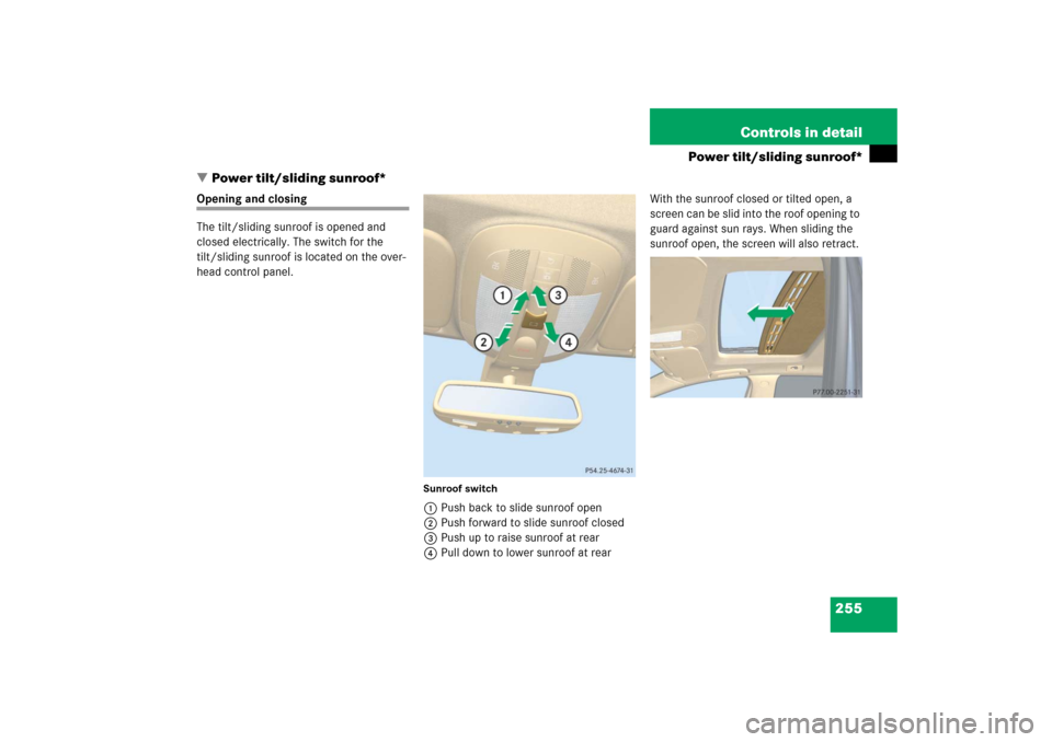
The tilt/sliding sunroof is opened and
closed electrically. The switch for the
tilt/sliding sunroof is located on the over-
head control panel.
Sunroof switch1Push back to slide sunroof open
2Push forward to slide sunroof closed
3Push up to raise sunroof at rear
4Pull down to lower sunroof at rearWith the sunroof closed or tilted open, a
screen can be slid into the roof opening to
guard against sun rays. When sliding the
sunroof open, the screen will also retract.
Page 259 of 561

258 Controls in detailPower tilt/sliding sunroof*Synchronizing
The tilt/sliding sunroof must be
synchronized�
after the battery has been
disconnected or discharged
�
after the tilt/sliding sunroof has been
closed manually (
�page 462)
�
after a malfunction
�
if the tilt/sliding sunroof does not open
smoothly
�
Remove the fuse securing the
tilt/sliding sunroof from the fuse box
(�page 503).
�
Reinsert the fuse in the main box.
�
Switch on the ignition (
�page 38).
�
Press and hold the sunroof switch in
the direction of arrow3 (
�page 255)
until the tilt/sliding sunroof is fully
raised at the rear.
�
Hold the sunroof switch in the direction
of arrow3 for approximately
1 second.
�
Open the tilt/sliding sunroof using the
Express-open feature (
�page 257).
If the tilt/sliding sunroof opens com-
pletely, it is synchronized.
If the tilt/sliding sunroof does not open
completely:
�
Repeat the above steps.
iFor information on which fuse box con-
tains the fuse for the power tilt/sliding
sunroof, see the fuse chart provided
with the vehicle tool kit (
�page 455).
Page 260 of 561

259 Controls in detail
Panorama roof with power tilt/sliding panel*
�Panorama roof with power tilt/sliding panel*
Roller sunblinds for the panorama roof with power tilt/sliding panel
The tilt/sliding panel and the front and
rear roller sunblinds are opened and
closed electrically. The switch for the
tilt/sliding panel and the roller sunblinds is
located on the overhead control panel.
The roller sunblinds only operate with the
tilt/sliding panel closed. The front and rear
roller sunblind cannot be operated individ-
ually.Roof panel switch1Open roller sunblinds
2Close roller sunblinds
�
Switch on the ignition (
�page 38).
�
To open or close the roller sunblinds,
move the roof panel switch to the resis-
tance point in the required direction of
arrow1 or2.
Release the roof panel switch when the
roller sunblinds have reached the de-
sired position.Fully opening the roller sunblinds (Ex-
press-open)
�
Move the roof panel switch past the re-
sistance point in direction of arrow1
and release.
The roller sunblinds opens completely.
Stopping the roller sunblinds during
Express-operation
�
Move the roof panel switch in any
direction.
Warning!
G
When closing the roller sunblinds, make
sure that no one is in danger of being injured
by the closing procedure. The closing of the
roller sunblinds can be immediately halted
by releasing the switch.
Page 263 of 561

262 Controls in detailPanorama roof with power tilt/sliding panel*Raising
You can raise the tilt/sliding panel at the
rear for better ventilation of the vehicle in-
terior.�
Press and hold the roof panel switch in
direction of arrow3 (
�page 260).
Release the roof panel switch when the
tilt/sliding panel has reached the de-
sired position.
Lowering
�
Pull and hold the roof panel switch in
direction of arrow4 (
�page 260) un-
til the tilt/sliding panel has lowered
and closed completely.Fully opening (Express-open) the pan-
orama roof with tilt/sliding panel
�
Pull the roof panel switch past the
resistance point in direction of
arrow1 (
�page 260) and release.
The tilt/sliding panel opens complete-
ly.
Stopping the panorama roof with
tilt/sliding panel during Express-open
�
Move the roof panel switch in any di-
rection.
The tilt/sliding panel will stop in its cur-
rent position.Synchronizing the panorama roof with
power tilt/sliding panel
The tilt/sliding panel and its roller sun-
blinds must be synchronized�
after the battery has been
disconnected or discharged
�
after a malfunction
�
if the tilt/sliding panel does not open
smoothly!Do not attempt to open or close the
tilt/sliding panel before the tilt/sliding
panel is properly synchronized. The
tilt/sliding panel could otherwise
lock-up in the open position.
If the tilt/sliding panel cannot be
closed or synchronized, see an autho-
rized Mercedes-Benz Light Truck
Center or call Roadside Assistance
(�page 315).
Page 264 of 561
 and
remove the SmartKey from the starter
switch.
Vehicles with KEYLESS-GO*:
�
Switch off the")
263 Controls in detail
Panorama roof with power tilt/sliding panel*
�
Switch off the ignition (
�page 38) and
remove the SmartKey from the starter
switch.
Vehicles with KEYLESS-GO*:
�
Switch off the ignition (
�page 39).
�
Open the driver’s door (this puts the
starter switch in position 0, same as
with the SmartKey removed from the
starter switch). The driver’s door then
can be closed again.
�
Remove the fuse securing the
tilt/sliding panel from the fuse box
(�page 504).
�
Reinsert the fuse in the fuse box.
�
Switch on the ignition (
�page 38).
�
Push and hold the roof panel switch in
direction of arrow2 (
�page 260) un-
til the roller sunblinds are fully closed.
�
Keep holding the roof panel switch in
direction of arrow2 (
�page 260) for
approximately 1 second.
�
Pull and hold the roof panel switch in
direction of arrow1 (
�page 260) un-
til the roller sunblinds are fully opened.
�
Keep holding the roof panel switch in
direction of arrow1 (
�page 260) for
approximately 1 second.
�
Press and hold the roof panel switch in
direction of arrow3 (
�page 260) un-
til the tilt/sliding panel is fully raised at
the rear.
�
Push and hold the roof panel switch in
direction of arrow2 (
�page 260) un-
til the tilt/sliding panel is fully closed.
�
Keep holding the roof panel switch in
direction of arrow2 (
�page 260) for
approximately 1 second.
�
Open the tilt/sliding panel using the
Express-open feature (
�page 262).
If the tilt/sliding panel opens com-
pletely, the roof is synchronized.
If the tilt/sliding sunroof does not open
completely:
�
Repeat the above steps.
iFor information on which fuse box con-
tains the fuse for the power tilt/sliding
panel, see the fuse chart provided with
the vehicle tool kit (
�page 455).
Page 275 of 561

The Parktronic system is an electronic aid
designed to assist the driver during
parking maneuvers. It visually and audibly
indicate")
274 Controls in detailDriving systemsParktronic* (Parking assist)
The Parktronic system is an electronic aid
designed to assist the driver during
parking maneuvers. It visually and audibly
indicates the relative distance between the
vehicle and an obstacle.
The Parktronic system is automatically
activated when you switch on the ignition,
release the parking brake, and set the
automatic transmission to positionD,R,
orN.
The Parktronic system deactivates at
vehicle speeds exceeding approximately
11 mph (18 km/h). At lower vehicle
speeds, the Parktronic system turns on
again.The Parktronic system also deactivates
when you set the automatic transmission
to positionP or depress the parking brake
pedal.
The Parktronic system monitors the sur-
roundings of your vehicle with six sensors
in the front bumper and four sensors in the
rear bumper.
1Sensors in the front bumperWarning!
G
Parktronic is a supplemental system. It is
not intended to, nor does it replace, the
need for extreme care. The responsibility
during parking and other critical maneuvers
always rests with the driver.
Special attention must be paid to objects
with smooth surfaces or low silhouettes
(e.g. trailer couplings, painted posts, or road
curbs). Such objects may not be detected by
the system and can damage the vehicle.
The operational function of the Parktronic
system can be affected by dirty sensors,
especially at times of snow and ice. See
“Cleaning the Parktronic system sensors”
(�page 399).
Interference caused by other ultrasonic
signals (e.g. working jackhammers, car
wash, or the air brakes of trucks) can cause
the system to send erratic indications, and
should be taken into consideration.
Warning!
G
Make sure no persons or animals are in the
area in which you are maneuvering. Other-
wise you run the risk of causing injury.
Page 276 of 561
275 Controls in detail
Driving systems
Range of the sensors
To function properly, the sensors must be
free of dirt, ice, snow and slush. Clean the
sensors regularly, being careful not to
scratch or damaging the sensors, see
“Cleaning the Parktronic* system sensors”
(�page 399).
Front sensors
Rear sensors
Center
approx. 40 in (100 cm)
Corners
approx. 24 in (60 cm)
Center
approx. 48 in (120 cm)
Corners
approx. 32 in (80 cm)
!During parking maneuvers, pay special
attention to objects located above or
below the height of the sensors
(e.g. planters or trailer hitches).
The Parktronic system will not detect
such objects at close range and dam-
age to your vehicle or the object may
result.
Ultrasonic signals from outside
sources (e.g. working jackhammers,
car wash or the air brakes of trucks)
may impair the operation of the
Parktronic system.
Page 277 of 561

276 Controls in detailDriving systemsMinimum distance
If the system detects an obstacle in this
range, all the distance warning segments
illuminate and you hear a warning signal. If
the obstacle is closer than the minimum
distance, the actual distance may no
longer be indicated by the system.Warning indicators
Visual signals indicate to the driver the rel-
ative distance between the sensors and an
obstacle. The warning indicator for the
front area is located above the center air
vents in the dashboard. The warning indi-
cator for the rear area is located in the rear
passenger compartment under the roof.
Front area warning indicator1Left side of the vehicle
2Right side of the vehicle
3Readiness indicatorsEach warning indicator is divided into five
yellow and two red distance segments for
either side of the vehicle. The Parktronic
system is ready when the yellow readiness
indicators3 are illuminated.
The current transmission position deter-
mines which warning indicator will be
activated.
Center
approx. 8 in (20 cm)
Corners
approx. 6 in (15 cm)
Transmission
position
Warning indicator
D
Front area activated
R or N
Front and rear area
activated
P
Neither activated