Page 2470 of 3383
AUTO LIGHT SYSTEMLT-63
C
DE
F
G H
I
J
L
M A
B
LT
Revision: November 2009 2006 QX56
Optical Sensor System InspectionEKS00B95
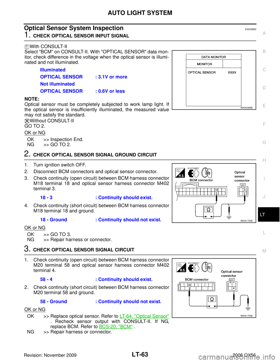
1. CHECK OPTICAL SENSOR INPUT SIGNAL
With CONSULT-II
Select "BCM" on CONSULT-II. With "OPTICAL SENSOR" data mon-
itor, check difference in the voltage when the optical sensor is illumi-
nated and not illuminated.
NOTE:
Optical sensor must be completely subjected to work lamp light. If
the optical sensor is insufficiently illuminated, the measured value
may not satisfy the standard.
Without CONSULT-II
GO TO 2.
OK or NG
OK >> Inspection End.
NG >> GO TO 2.
2. CHECK OPTICAL SENSOR SIGNAL GROUND CIRCUIT
1. Turn ignition switch OFF.
2. Disconnect BCM connectors and optical sensor connector.
3. Check continuity (open circuit) between BCM harness connector M18 terminal 18 and optical sensor harness connector M402
terminal 3.
4. Check continuity (short circuit) between BCM harness connector M18 terminal 18 and ground.
OK or NG
OK >> GO TO 3.
NG >> Repair harness or connector.
3. CHECK OPTICAL SENSOR SIGNAL CIRCUIT
1. Check continuity (open circuit) between BCM harness connector M20 terminal 58 and optical sensor harness connector M402
terminal 4.
2. Check continuity (short circuit) between BCM harness connector M20 terminal 58 and ground.
OK or NG
OK >> Replace optical sensor. Refer to LT- 6 4 , "Optical Sensor"
. Recheck sensor output with CONSULT-II. If NG,
replace BCM. Refer to BCS-20, "
BCM" .
NG >> Repair harness or connector. Illuminated
OPTICAL SENSOR : 3.1V or more
Not illuminated
OPTICAL SENSOR : 0.6V or less
WKIA0486E
18 - 3
: Continuity should exist.
18 - Ground : Continuity should not exist.
WKIA1754E
58 - 4: Continuity should exist.
58 - Ground : Continuity should not exist.
WKIA1755E
Page 2471 of 3383
LT-64
AUTO LIGHT SYSTEM
Revision: November 20092006 QX56
Optical SensorEKS00B96
REMOVAL AND INSTALLATION
Removal
1. Remove defrost grille. Refer to IP-10, "INSTRUMENT PANEL ASSEMBLY" .
2. Disconnect the connector.
3. Turn the optical sensor counterclockwise to remove it from defroster grille.
Installation
Installation is in the reverse order of removal.
WKIA1061E
Page 2590 of 3383
ENGINE OILLU-7
C
DE
F
G H
I
J
K L
M A
LU
Revision: November 2009 2006 QX56
ENGINE OILPFP:KLA92
InspectionEBS00LMS
OIL LEVEL
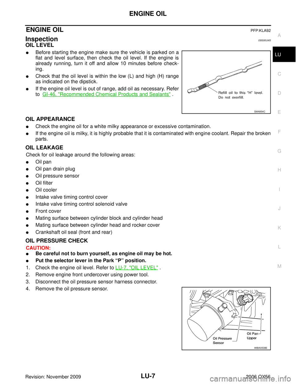
�Before starting the engine make sure the vehicle is parked on a
flat and level surface, then check the oil level. If the engine is
already running, turn it off and allow 10 minutes before check-
ing.
�Check that the oil level is within the low (L) and high (H) range
as indicated on the dipstick.
�If the engine oil level is out of range, add oil as necessary. Refer
to GI-46, "
Recommended Chemical Products and Sealants" .
OIL APPEARANCE
�Check the engine oil for a white milky appearance or excessive contamination.
�If the engine oil is milky, it is highly probable that it is contaminated with engine coolant. Repair the broken
parts.
OIL LEAKAGE
Check for oil leakage around the following areas:
�Oil pan
�Oil pan drain plug
�Oil pressure sensor
�Oil filter
�Oil cooler
�Intake valve timing control cover
�Intake valve timing control solenoid valve
�Front cover
�Mating surface between cylinder block and cylinder head
�Mating surface between cylinder head and rocker cover
�Crankshaft oil seal (front and rear)
OIL PRESSURE CHECK
CAUTION:
�Be careful not to burn yourself, as engine oil may be hot.
�Put the selector lever in the Park “P” position.
1. Check the engine oil level. Refer to LU-7, "
OIL LEVEL" .
2. Remove engine front undercover using power tool.
3. Disconnect the oil pressure sensor harness connector.
4. Remove the oil pressure sensor.
SMA954C
WBIA0538E
Page 2591 of 3383
LU-8Revision: November 2009
ENGINE OIL
2006 QX56
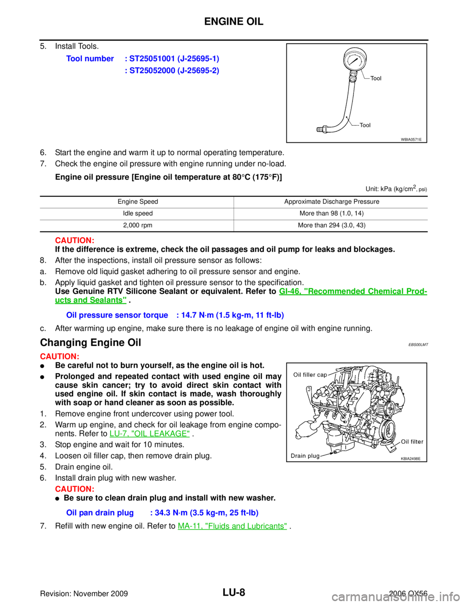
5. Install Tools.
6. Start the engine and warm it up to normal operating temperature.
7. Check the engine oil pressure with engine running under no-load.Engine oil pressure [Engine oil temperature at 80 °C (175 °F)]
Unit: kPa (kg/cm2
, psi)
CAUTION:
If the difference is extreme, check the oil passages and oil pump for leaks and blockages.
8. After the inspections, install oil pressure sensor as follows:
a. Remove old liquid gasket adhering to oil pressure sensor and engine.
b. Apply liquid gasket and tighten oil pressure sensor to the specification. Use Genuine RTV Silicone Sealant or equivalent. Refer to GI-46, "
Recommended Chemical Prod-
ucts and Sealants" .
c. After warming up engine, make sure there is no leakage of engine oil with engine running.
Changing Engine OilEBS00LMT
CAUTION:
�Be careful not to burn yourself, as the engine oil is hot.
�Prolonged and repeated contact with used engine oil may
cause skin cancer; try to avoid direct skin contact with
used engine oil. If skin contact is made, wash thoroughly
with soap or hand cleaner as soon as possible.
1. Remove engine front undercover using power tool.
2. Warm up engine, and check for oil leakage from engine compo- nents. Refer to LU-7, "
OIL LEAKAGE" .
3. Stop engine and wait for 10 minutes.
4. Loosen oil filler cap, then remove drain plug.
5. Drain engine oil.
6. Install drain plug with new washer.
CAUTION:
�Be sure to clean drain plug and install with new washer.
7. Refill with new engine oil. Refer to MA-11, "
Fluids and Lubricants" .
Tool number : ST25051001 (J-25695-1)
: ST25052000 (J-25695-2)
WBIA0571E
Engine Speed Approximate Discharge Pressure
Idle speed More than 98 (1.0, 14)
2,000 rpm More than 294 (3.0, 43)
Oil pressure sensor torque : 14.7 N·m (1.5 kg-m, 11 ft-lb)
Oil pan drain plug : 34.3 N·m (3.5 kg-m, 25 ft-lb)
KBIA2498E
Page 2615 of 3383
MA-16
ENGINE MAINTENANCE
Revision: November 20092006 QX56
3. Run the engine until it reaches normal operating temperature.
4. Press the engine accelerator two or three times under no-load.
5. Stop the engine and wait until it cools down.
6. Drain the water from the engine cooling system. Refer to MA-13, "
DRAINING ENGINE COOLANT" .
7. Repeat steps 2 through 6 until clear water begins to drain from the radiator.
Checking Fuel LinesELS001PI
Inspect the fuel lines and fuel tank for improper mounting, leaks,
cracks, damage, loose connections, chafing, or deterioration.
As necessary, repair or replace any faulty parts.
Changing Fuel FilterELS001PJ
The fuel filter is part of the fuel level sensor unit, fuel filter and fuel pump assembly. Refer to FL-6, "FUEL
LEVEL SENSOR UNIT, FUEL FILTER AND FUEL PUMP ASSEMBLY" .
WARNING:
Before replacing the fuel filter, release the fuel pressure from the fuel system. Refer to EC-80, "
FUEL
PRESSURE RELEASE" .
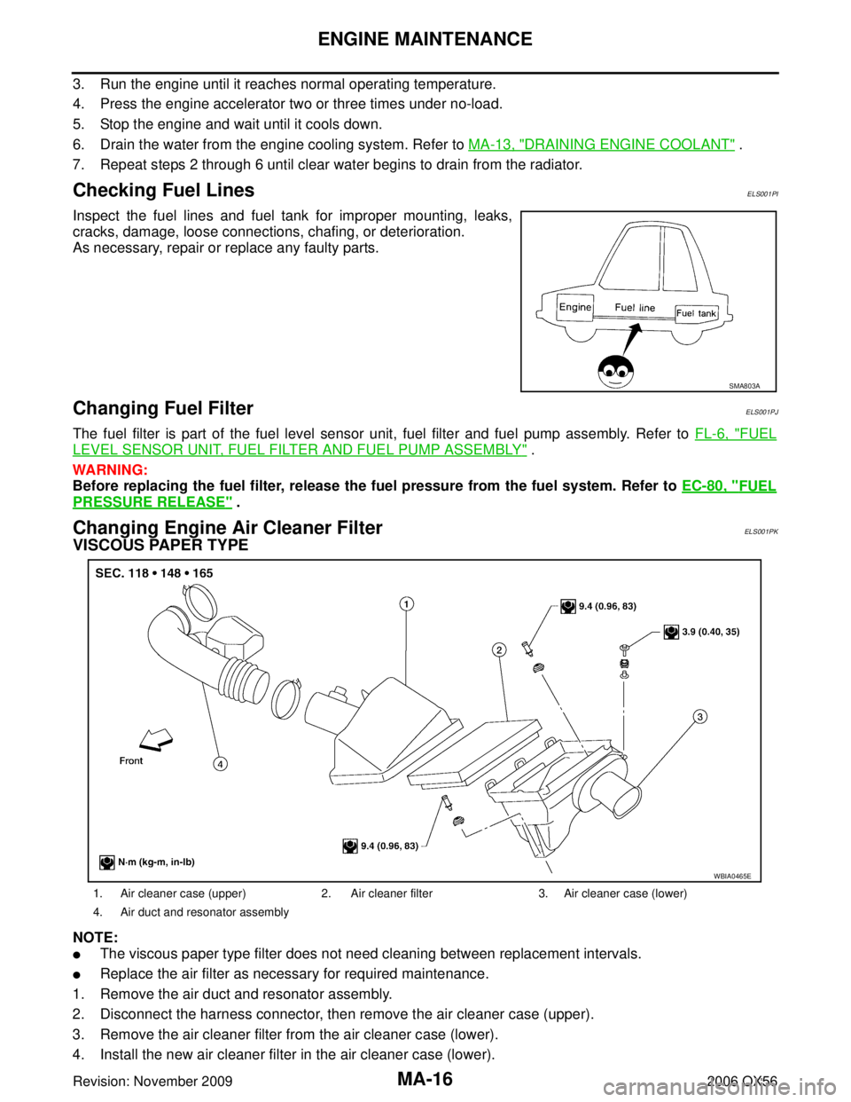
Changing Engine Air Cleaner FilterELS001PK
VISCOUS PAPER TYPE
NOTE:
�The viscous paper type filter does not need cleaning between replacement intervals.
�Replace the air filter as necessary for required maintenance.
1. Remove the air duct and resonator assembly.
2. Disconnect the harness connector, then remove the air cleaner case (upper).
3. Remove the air cleaner filter from the air cleaner case (lower).
4. Install the new air cleaner filter in the air cleaner case (lower).
SMA803A
1. Air cleaner case (upper) 2. Air cleaner filter3. Air cleaner case (lower)
4. Air duct and resonator assembly
WBIA0465E
Page 2637 of 3383
PB-6
PARKING BRAKE SHOE
Revision: November 20092006 QX56
PARKING BRAKE SHOEPFP:44060
Removal and InstallationEFS0068M
COMPONENTS
REMOVAL
WARNING:
Clean the brakes with a vacuum dust collector to minimize the hazard of airborne particles or other
materials.
NOTE:
Remove the disc rotor only with the parking brake pedal completely disengaged.
1. Remove wheel hub and bearing assembly. Refer to FAX-5, "
Removal and Installation" .
�Disconnect the wheel sensor at the harness connector. It is not necessary to remove the wheel sensor
from the wheel hub and bearing assembly.
2. Remove the return springs.
3. Remove the adjuster.
4. Remove the retainers, anti-rattle pins and shoes.
5. Disconnect the rear cable from the toggle lever.
6. Remove the back plate.
1. Back plate 2. Shoes 3. Toggle lever
4. Return springs 5. Retainers 6. Adjuster
7. Anti-rattle pins
WFIA0164E
Page 2682 of 3383
HARNESSPG-41
C
DE
F
G H
I
J
L
M A
B
PG
Revision: November 2009 2006 QX56
HARNESSPFP:24010
Harness LayoutEKS00BND
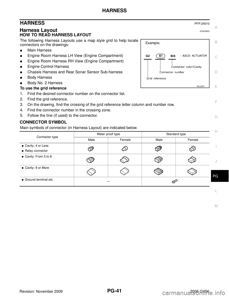
HOW TO READ HARNESS LAYOUT
The following Harness Layouts use a map style grid to help locate
connectors on the drawings:
�Main Harness
�Engine Room Harness LH View (Engine Compartment)
�Engine Room Harness RH View (Engine Compartment)
�Engine Control Harness
�Chassis Harness and Rear Sonar Sensor Sub-harness
�Body Harness
�Body No. 2 Harness
To use the grid reference
1. Find the desired connector number on the connector list.
2. Find the grid reference.
3. On the drawing, find the crossing of the grid reference letter column and number row.
4. Find the connector number in the crossing zone.
5. Follow the line (if used) to the connector.
CONNECTOR SYMBOL
Main symbols of connector (in Harness Layout) are indicated below.
SEL252V
Connector type Water proof type Standard type
Male Female Male Female
�Cavity: 4 or Less
�Relay connector
�Cavity: From 5 to 8
�Cavity: 9 or More
�Ground terminal etc. —
Page 2703 of 3383

PG-62
HARNESS
Revision: November 20092006 QX56
Wiring Diagram Codes (Cell Codes)EKS00BNE
Use the chart below to find out what each wiring diagram code stands for.
Refer to the wiring diagram code in the alphabetical index to find the location (page number) of each wiring
diagram.
CodeSection Wiring Diagram Name
A/C,A ATC Auto Air Conditioner
A/SUSP RSU Rear Air Suspension
AF1B1 EC Air Fuel Ratio (A/F) Sensor 1 (Bank 1)
AF1B2 EC Air Fuel Ratio (A/F) Sensor 1 (Bank 2)
AF1HB1 EC Air Fuel Ratio (A/F) Sensor 1 (Bank 1)
AF1HB2 EC Air Fuel Ratio (A/F) Sensor 1 (Bank 2)
APPS1 EC Accelerator Pedal Position Sensor
APPS2 EC Accelerator Pedal Position Sensor
APPS3 EC Accelerator Pedal Position Sensor
ASC/BS EC ASCD Brake Switch
ASC/SW EC ASCD Steering Switch
ASCBOF EC ASCD Brake Switch
ASCIND EC ASCD Indicator
A/T AT A/T Assembly
AT/IND DI A/T Indicator Lamp
AUDIO AV Audio
AUT/DP SE Automatic Drive Positioner
AUTO/L LT Auto Light Control
B/CLOS BL Back Door Auto Closure System
BACK/L LT Back-up Lamp
BRK/SW EC Brake Switch
CAN EC CAN Communication Line
CAN LAN CAN System
CHARGE SC Charging System
CHIME DI Warning Chime
CLOCK DI Clock
COOL/F EC Cooling Fan Control
COMBSW LT Combination Switch
COMM AV Audio Visual Communication System
COMPAS DI Compass and Thermometer
D/LOCK BL Power Door Lock
DEF GW Rear Window Defogger
DTRL LT Headlamp - With Daytime Light System
DVD AV DVD Entertainment System
ECM/PW EC ECM Power Supply for Back-Up
ECTS EC Engine Coolant Temperature Sensor
ETC1 EC Electric Throttle Control Function
ETC2 EC Throttle Control Motor Relay
ETC3 EC Throttle Control Motor
F/FOG LT Front Fog Lamp
F/PUMP EC Fuel Pump
FTTS EC Fuel Tank Temperature Sensor
FUELB1 EC Fuel Injection System Bank 1
FUELB2 EC Fuel Injection System Bank 2
H/AIM LT Headlamp Aiming Control
H/PHON AV Hands Free Telephone
H/LAMP LT Headlamp