Page 1360 of 3383

POWER SUPPLY AND GROUND CIRCUITEC-149
C
DE
F
G H
I
J
K L
M A
EC
Revision: November 2009 2006 QX56
12. CHECK 20A FUSE
1. Disconnect 20A fuse from IPDM E/R.
2. Check 20A fuse.
OK or NG
OK >> GO TO 16.
NG >> Replace 20A fuse.
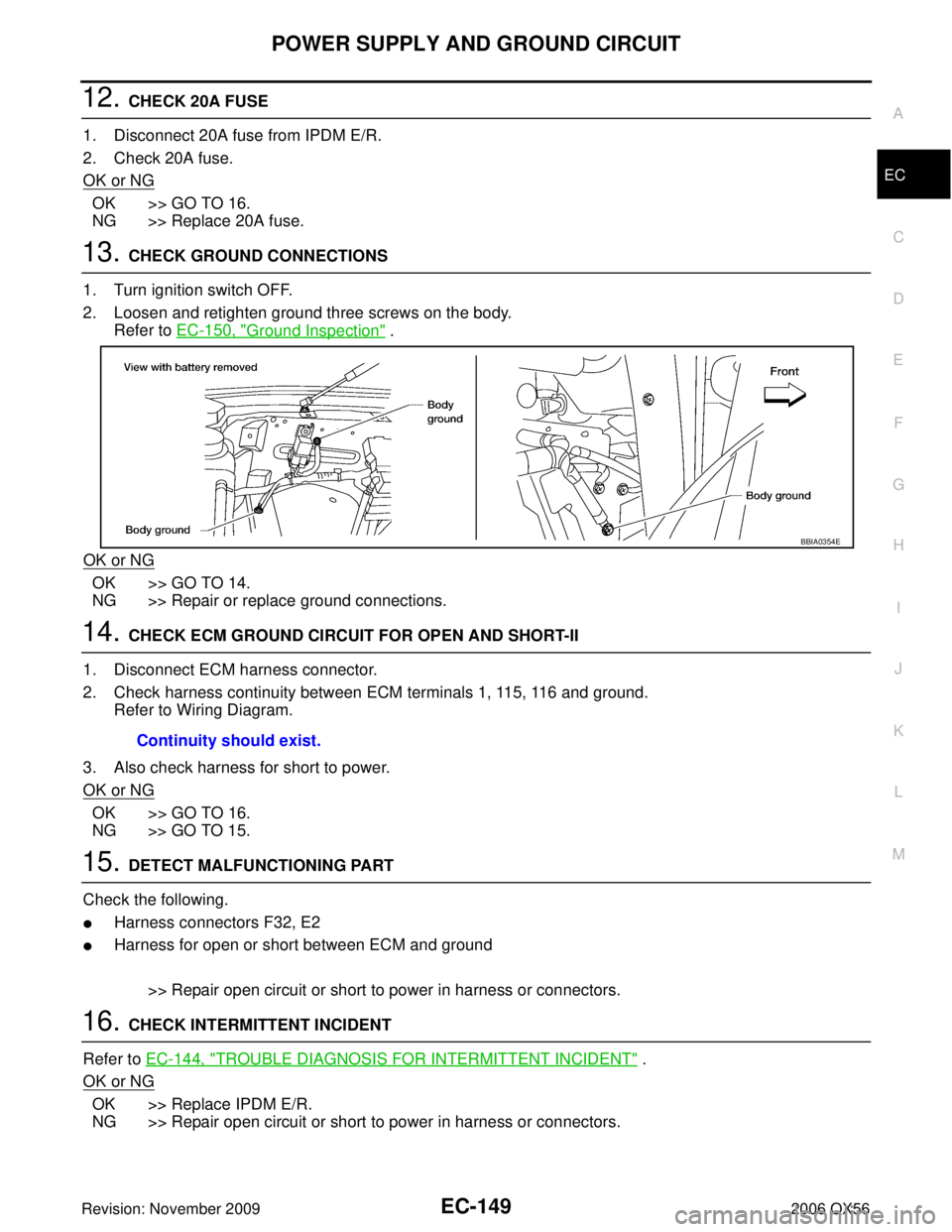
13. CHECK GROUND CONNECTIONS
1. Turn ignition switch OFF.
2. Loosen and retighten ground three screws on the body. Refer to EC-150, "
Ground Inspection" .
OK or NG
OK >> GO TO 14.
NG >> Repair or replace ground connections.
14. CHECK ECM GROUND CIRCUIT FOR OPEN AND SHORT-II
1. Disconnect ECM harness connector.
2. Check harness continuity between ECM terminals 1, 115, 116 and ground. Refer to Wiring Diagram.
3. Also check harness for short to power.
OK or NG
OK >> GO TO 16.
NG >> GO TO 15.
15. DETECT MALFUNCTIONING PART
Check the following.
�Harness connectors F32, E2
�Harness for open or short between ECM and ground
>> Repair open circuit or short to power in harness or connectors.
16. CHECK INTERMITTENT INCIDENT
Refer to EC-144, "
TROUBLE DIAGNOSIS FOR INTERMITTENT INCIDENT" .
OK or NG
OK >> Replace IPDM E/R.
NG >> Repair open circuit or short to power in harness or connectors.
BBIA0354E
Continuity should exist.
Page 1363 of 3383
EC-152Revision: November 2009
DTC U1000, U1001 CAN COMMUNICATION LINE
2006 QX56
Wiring DiagramUBS00H0L
BBWA1671E
Page 1368 of 3383
DTC P0031, P0032, P0051, P0052 A/F SENSOR 1 HEATEREC-157
C
DE
F
G H
I
J
K L
M A
EC
Revision: November 2009 2006 QX56
Wiring DiagramUBS00H75
BANK 1
BBWA2113E
Page 1372 of 3383

DTC P0031, P0032, P0051, P0052 A/F SENSOR 1 HEATEREC-161
C
DE
F
G H
I
J
K L
M A
EC
Revision: November 2009 2006 QX56
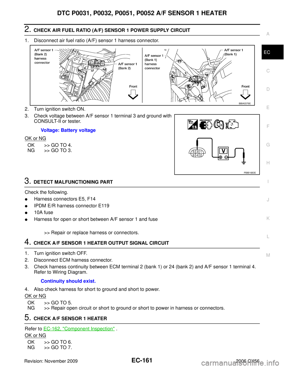
2. CHECK AIR FUEL RATIO (A/F) SENSOR 1 POWER SUPPLY CIRCUIT
1. Disconnect air fuel ratio (A/F) sensor 1 harness connector.
2. Turn ignition switch ON.
3. Check voltage between A/F sensor 1 terminal 3 and ground with CONSULT-II or tester.
OK or NG
OK >> GO TO 4.
NG >> GO TO 3.
3. DETECT MALFUNCTIONING PART
Check the following.
�Harness connectors E5, F14
�IPDM E/R harness connector E119
�10A fuse
�Harness for open or short between A/F sensor 1 and fuse
>> Repair or replace harness or connectors.
4. CHECK A/F SENSOR 1 HEATER OUTPUT SIGNAL CIRCUIT
1. Turn ignition switch OFF.
2. Disconnect ECM harness connector.
3. Check harness continuity between ECM terminal 2 (bank 1) or 24 (bank 2) and A/F sensor 1 terminal 4. Refer to Wiring Diagram.
4. Also check harness for short to ground and short to power.
OK or NG
OK >> GO TO 5.
NG >> Repair open circuit or short to ground or short to power in harness or connectors.
5. CHECK A/F SENSOR 1 HEATER
Refer to EC-162, "
Component Inspection" .
OK or NG
OK >> GO TO 6.
NG >> GO TO 7. Voltage: Battery voltage
BBIA0376E
PBIB1683E
Continuity should exist.
Page 1376 of 3383
DTC P0037, P0038, P0057, P0058 HO2S2 HEATEREC-165
C
DE
F
G H
I
J
K L
M A
EC
Revision: November 2009 2006 QX56
Wiring DiagramUBS00H0R
BANK 1
BBWA1672E
Page 1380 of 3383

DTC P0037, P0038, P0057, P0058 HO2S2 HEATEREC-169
C
DE
F
G H
I
J
K L
M A
EC
Revision: November 2009 2006 QX56
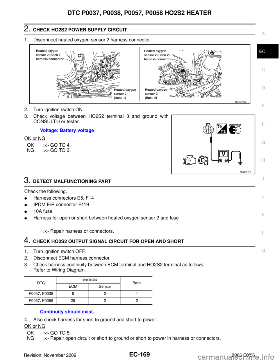
2. CHECK HO2S2 POWER SUPPLY CIRCUIT
1. Disconnect heated oxygen sensor 2 harness connector.
2. Turn ignition switch ON.
3. Check voltage between HO2S2 terminal 3 and ground with CONSULT-II or tester.
OK or NG
OK >> GO TO 4.
NG >> GO TO 3.
3. DETECT MALFUNCTIONING PART
Check the following.
�Harness connectors E5, F14
�IPDM E/R connector E119
�10A fuse
�Harness for open or short between heated oxygen sensor 2 and fuse
>> Repair harness or connectors.
4. CHECK HO2S2 OUTPUT SIGNAL CIRCUIT FOR OPEN AND SHORT
1. Turn ignition switch OFF.
2. Disconnect ECM harness connector.
3. Check harness continuity between ECM terminal and HO2S2 terminal as follows. Refer to Wiring Diagram.
4. Also check harness for short to ground and short to power.
OK or NG
OK >> GO TO 5.
NG >> Repair open circuit or short to ground or short to power in harness or connectors.
BBIA0435E
Voltage: Battery voltage
PBIB0112E
DTC Te r m i n a l s
Bank
ECM Sensor
P0037, P0038 6 21
P0057, P0058 25 22
Continuity should exist.
Page 1385 of 3383
EC-174Revision: November 2009
DTC P0101 MAF SENSOR
2006 QX56
Wiring DiagramUBS00H10
BBWA1674E
Page 1388 of 3383

DTC P0101 MAF SENSOREC-177
C
DE
F
G H
I
J
K L
M A
EC
Revision: November 2009 2006 QX56
6. CHECK MAF SENSOR GROUND CIRCUIT FOR OPEN AND SHORT
1. Turn ignition switch OFF.
2. Disconnect ECM harness connector.
3. Check harness continuity between MAF sensor terminal 3 and ECM terminal 67. Refer to Wiring Diagram.
4. Also check harness for short to ground and short to power.
OK or NG
OK >> GO TO 7.
NG >> Repair open circuit or short to ground or short to power in harness or connectors.
7. CHECK MAF SENSOR INPUT SIGNAL CIRCUIT FOR OPEN AND SHORT
1. Check harness continuity between MAF sensor terminal 4 and ECM terminal 51. Refer to Wiring Diagram.
2. Also check harness for short to ground and short to power.
OK or NG
OK >> GO TO 8.
NG >> Repair open circuit or short to ground or short to power in harness or connectors.
8. CHECK INTAKE AIR TEMPERATURE SENSOR
Refer to EC-191, "
Component Inspection" .
OK or NG
OK >> GO TO 9.
NG >> Replace intake air temperature sensor.
9. CHECK EVAP CONTROL SYSTEM PRESSURE SENSOR
Refer to EC-404, "
Component Inspection" .
OK or NG
OK >> GO TO 10.
NG >> Replace EVAP control system pressure sensor.
10. CHECK MASS AIR FLOW SENSOR
Refer to EC-178, "
Component Inspection" .
OK or NG
OK >> GO TO 11.
NG >> Replace mass air flow sensor.
11 . CHECK INTERMITTENT INCIDENT
Refer to EC-144, "
TROUBLE DIAGNOSIS FOR INTERMITTENT INCIDENT" .
>> INSPECTION END
Continuity should exist.
Continuity should exist.