Page 1167 of 3383
DI-46
WARNING CHIME
Revision: November 20092006 QX56
Wiring Diagram — CHIME —EKS00BCR
WKWA3627E
Page 1171 of 3383

DI-50
WARNING CHIME
Revision: November 20092006 QX56
Preliminary CheckEKS00BCV
INSPECTION FOR POWER SUPPLY AND GROUND CIRCUIT
1. CHECK FUSE AND FUSIBLE LINK
Check for blown BCM fuse or fusible link.
Refer to DI-46, "Wiring Diagram — CHIME —" .
OK or NG
OK >> GO TO 2.
NG >> If fuse is blown, be sure to eliminate cause of malfunction before installing new fuse. Refer to PG-
4, "POWER SUPPLY ROUTING CIRCUIT" .
2. CHECK POWER SUPPLY CIRCUIT
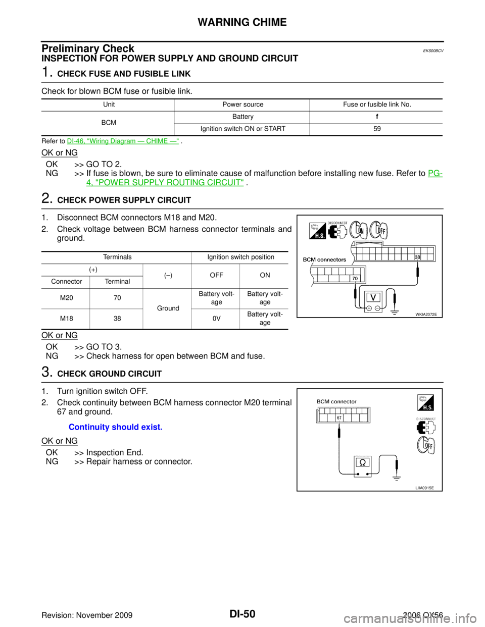
1. Disconnect BCM connectors M18 and M20.
2. Check voltage between BCM harness connector terminals and ground.
OK or NG
OK >> GO TO 3.
NG >> Check harness for open between BCM and fuse.
3. CHECK GROUND CIRCUIT
1. Turn ignition switch OFF.
2. Check continuity between BCM harness connector M20 terminal 67 and ground.
OK or NG
OK >> Inspection End.
NG >> Repair harness or connector.
Unit Power source Fuse or fusible link No.
BCM Battery
f
Ignition switch ON or START 59
TerminalsIgnition switch position
(+) (– )O FFO N
Connector Terminal
M20 70
GroundBattery volt-
age Battery volt-
age
M18 38 0VBattery volt-
age
WKIA2072E
Continuity should exist.
LIIA0915E
Page 1176 of 3383

WARNING CHIMEDI-55
C
DE
F
G H
I
J
L
M A
B
DI
Revision: November 2009 2006 QX56
3. CHECK FRONT DOOR SWITCH LH
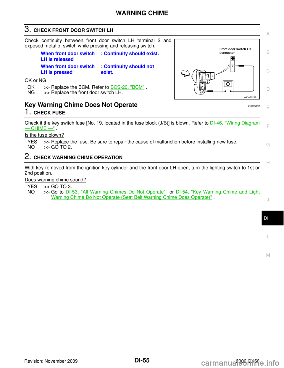
Check continuity between front door switch LH terminal 2 and
exposed metal of switch while pressing and releasing switch.
OK or NG
OK >> Replace the BCM. Refer to BCS-20, "BCM" .
NG >> Replace the front door switch LH.
Key Warning Chime Does Not OperateEKS00BCZ
1. CHECK FUSE
Check if the key switch fuse [No. 19, located in the fuse block (J/B)] is blown. Refer to DI-46, "
Wiring Diagram
— CHIME —" .
Is the fuse blown?
YES >> Replace the fuse. Be sure to repair the cause of malfunction before installing new fuse.
NO >> GO TO 2.
2. CHECK WARNING CHIME OPERATION
With key removed from the ignition key cylinder and the front door LH open, turn the lighting switch to 1st or
2nd position.
Does warning chime sound?
YES >> GO TO 3.
NO >> Go to DI-53, "
All Warning Chimes Do Not Operate" or DI-54, "Key Warning Chime and Light
Warning Chime Do Not Operate (Seat Belt Warning Chime Does Operate)" .
When front door switch
LH is released
: Continuity should exist.
When front door switch
LH is pressed : Continuity should not
exist.
WKIA2023E
Page 1184 of 3383
REAR SONAR SYSTEMDI-63
C
DE
F
G H
I
J
L
M A
B
DI
Revision: November 2009 2006 QX56
Wiring Diagram — SONAR —EKS00BD4
WKWA4087E
Page 1189 of 3383

DI-68
REAR SONAR SYSTEM
Revision: November 20092006 QX56
Preliminary CheckEKS00BD9
INSPECTION FOR POWER SUPPLY AND GROUND CIRCUIT
1. CHECK FUSE
Check for blown rear sonar system fuse.
Refer to DI-63, "
Wiring Diagram — SONAR —" .
OK or NG
OK >> GO TO 2.
NG >> If fuse is blown, be sure to eliminate cause of problem before installing new fuse. Refer to PG-4,
"POWER SUPPLY ROUTING CIRCUIT" .
2. CHECK POWER SUPPLY CIRCUIT
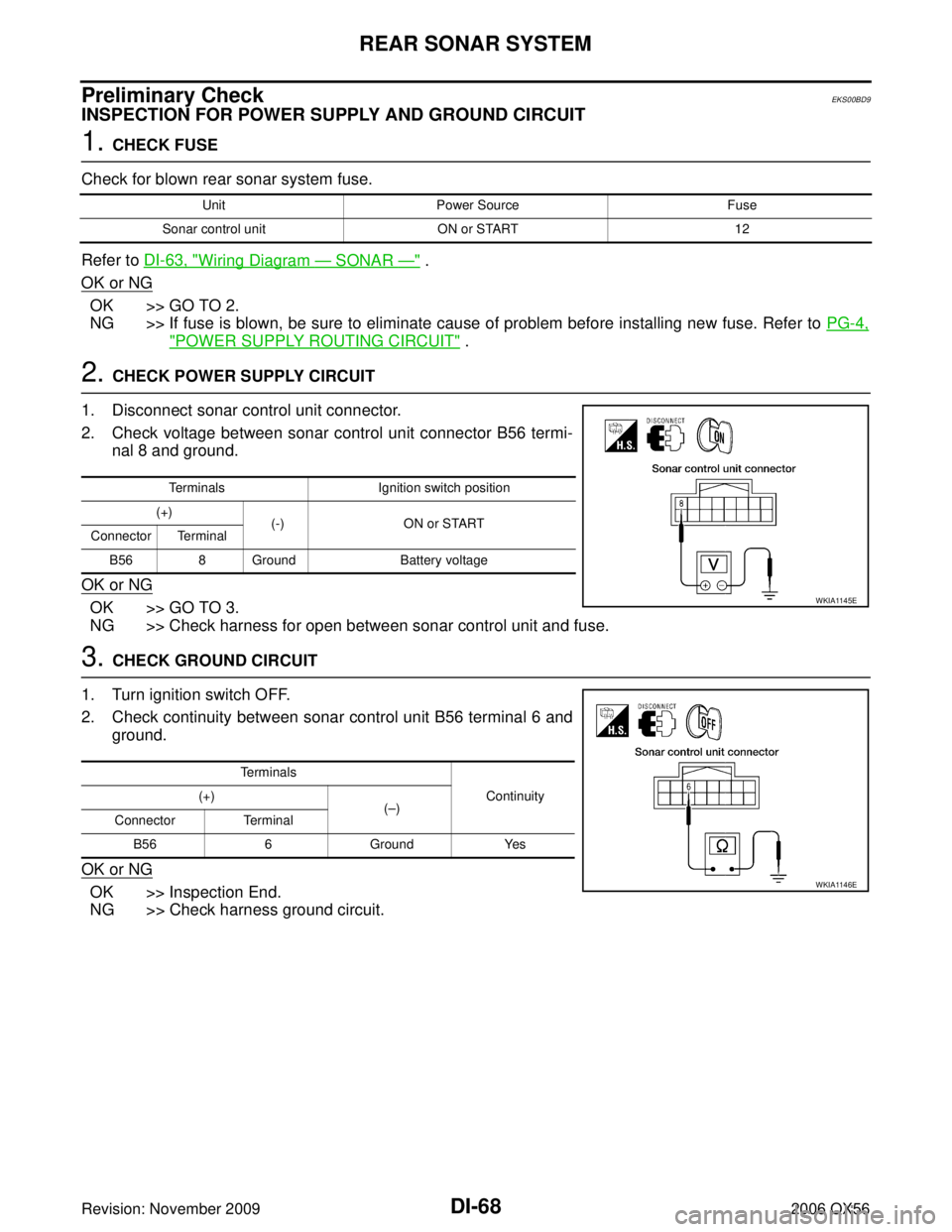
1. Disconnect sonar control unit connector.
2. Check voltage between sonar control unit connector B56 termi- nal 8 and ground.
OK or NG
OK >> GO TO 3.
NG >> Check harness for open between sonar control unit and fuse.
3. CHECK GROUND CIRCUIT
1. Turn ignition switch OFF.
2. Check continuity between sonar control unit B56 terminal 6 and ground.
OK or NG
OK >> Inspection End.
NG >> Check harness ground circuit.
Unit Power Source Fuse
Sonar control unit ON or START 12
TerminalsIgnition switch position
(+) (-) ON or START
Connector Terminal
B56 8 Ground Battery voltage
WKIA1145E
Terminals
Continuity
(+)
(– )
Connector Terminal
B56 6 Ground Yes
WKIA1146E
Page 1192 of 3383
CLOCKDI-71
C
DE
F
G H
I
J
L
M A
B
DI
Revision: November 2009 2006 QX56
CLOCKPFP:25820
Wiring Diagram — CLOCK —EKS00BDD
WKWA1178E
Page 1197 of 3383
DI-76
REAR VIEW MONITOR
Revision: November 20092006 QX56
Wiring Diagram — R/VIEW —EKS00BDI
WKWA1180E
Page 1213 of 3383

EC-2Revision: November 20092006 QX56
Description ...........................................................
.144
Diagnostic Procedure .......................................... .144
POWER SUPPLY AND GROUND CIRCUIT .......... .145
Wiring Diagram .................................................... .145
Diagnostic Procedure .......................................... .146
Ground Inspection ............................................... .150
DTC U1000, U1001 CAN COMMUNICATION LINE .151
Description ........................................................... .151
On Board Diagnosis Logic ................................... .151
DTC Confirmation Procedure .............................. .151
Wiring Diagram .................................................... .152
Diagnostic Procedure .......................................... .153
DTC U1010 CAN COMMUNICATION .................... .154
Description ........................................................... .154
On Board Diagnosis Logic ................................... .154
DTC Confirmation Procedure .............................. .154
Diagnostic Procedure .......................................... .155
DTC P0031, P0032, P0051, P0052 A/F SENSOR 1
HEATER ................................................................. .156
Description ........................................................... .156
CONSULT-II Reference Value in Data Monitor Mode .156
On Board Diagnosis Logic ................................... .156
DTC Confirmation Procedure .............................. .156
Wiring Diagram .................................................... .157
Diagnostic Procedure .......................................... .160
Component Inspection ......................................... .162
Removal and Installation ..................................... .162
DTC P0037, P0038, P0057, P0058 HO2S2 HEATER .163
Description ........................................................... .163
CONSULT-II Reference Value in Data Monitor Mode .163
On Board Diagnosis Logic ................................... .163
DTC Confirmation Procedure .............................. .164
Wiring Diagram .................................................... .165
Diagnostic Procedure .......................................... .168
Component Inspection ......................................... .170
Removal and Installation ..................................... .170
DTC P0101 MAF SENSOR .................................... .171
Component Description ....................................... .171
CONSULT-II Reference Value in Data Monitor Mode .171
On Board Diagnosis Logic ................................... .171
DTC Confirmation Procedure .............................. .172
Overall Function Check ....................................... .173
Wiring Diagram .................................................... .174
Diagnostic Procedure .......................................... .175
Component Inspection ......................................... .178
Removal and Installation ..................................... .179
DTC P0102, P0103 MAF SENSOR ........................ .180
Component Description ....................................... .180
CONSULT-II Reference Value in Data Monitor Mode .180
On Board Diagnosis Logic ................................... .180
DTC Confirmation Procedure .............................. .181
Wiring Diagram .................................................... .182
Diagnostic Procedure .......................................... .183
Component Inspection ......................................... .186
Removal and Installation ..................................... .187DTC P0112, P0113 IAT SENSOR ...........................
.188
Component Description ....................................... .188
On Board Diagnosis Logic ................................... .188
DTC Confirmation Procedure ............................... .188
Wiring Diagram .................................................... .189
Diagnostic Procedure ........................................... .190
Component Inspection ......................................... .191
Removal and Installation ...................................... .191
DTC P0117, P0118 ECT SENSOR ......................... .192
Component Description ....................................... .192
On Board Diagnosis Logic ................................... .192
DTC Confirmation Procedure ............................... .193
Wiring Diagram .................................................... .194
Diagnostic Procedure ........................................... .195
Component Inspection ......................................... .196
Removal and Installation ...................................... .197
DTC P0122, P0123 TP SENSOR ........................... .198
Component Description ....................................... .198
CONSULT-II Reference Value in Data Monitor Mode .198
On Board Diagnosis Logic ................................... .198
DTC Confirmation Procedure ............................... .199
Wiring Diagram .................................................... .200
Diagnostic Procedure ........................................... .201
Component Inspection ......................................... .204
Removal and Installation ...................................... .204
DTC P0125 ECT SENSOR ..................................... .205
Component Description ....................................... .205
On Board Diagnosis Logic ................................... .205
DTC Confirmation Procedure ............................... .206
Diagnostic Procedure ........................................... .206
Component Inspection ......................................... .207
Removal and Installation ...................................... .207
DTC P0127 IAT SENSOR ....................................... .208
Component Description ....................................... .208
On Board Diagnosis Logic ................................... .208
DTC Confirmation Procedure ............................... .208
Diagnostic Procedure ........................................... .209
Component Inspection ......................................... .210
Removal and Installation ...................................... .210
DTC P0128 THERMOSTAT FUNCTION ................ .211
On Board Diagnosis Logic ................................... .211
DTC Confirmation Procedure ............................... .211
Diagnostic Procedure ........................................... .211
Component Inspection ......................................... .212
Removal and Installation ...................................... .212
DTC P0130, P0150 A/F SENSOR 1 ....................... .213
Component Description ....................................... .213
CONSULT-II Reference Value in Data Monitor Mode .213
On Board Diagnosis Logic ................................... .213
DTC Confirmation Procedure ............................... .213
Overall Function Check ........................................ .214
Wiring Diagram .................................................... .216
Diagnostic Procedure ........................................... .219
Removal and Installation ...................................... .222
DTC P0131, P0151 A/F SENSOR 1 ....................... .223
Component Description ....................................... .223
CONSULT-II Reference Value in Data Monitor Mode