Page 2564 of 3383

ILLUMINATIONLT-157
C
DE
F
G H
I
J
L
M A
B
LT
Revision: November 2009 2006 QX56
ILLUMINATIONPFP:27545
Component Parts and Harness Connector LocationEKS00BBI
System DescriptionEKS00BBJ
Control of the illumination lamps operation is dependent upon the position of the lighting switch (combination
switch). When the lighting switch is placed in the 1ST or 2ND position (or if the auto light system is activated)
the BCM (body control module) receives input signal requesting the illumination lamps to illuminate. This input
signal is communicated to the IPDM E/R (intelligent power distribution module engine room) across the CAN
communication lines. The CPU (central processing unit) of the IPDM E/R controls the tail lamp relay coil. This
relay, when energized, directs power to the illumination lamps, which then illuminate.
Power is supplied at all times
�to ignition relay, located in the IPDM E/R, and
�to tail lamp relay, located in the IPDM E/R, and
�through 50A fusible link (letter f , located in the fuse and fusible link box)
�to BCM terminal 70, and
�through 20A fuse (No. 53, located in the IPDM E/R)
�to CPU of the IPDM E/R, and
�through 10A fuse [No.19, located in fuse block (J/B)]
WKIA3471E
Page 2565 of 3383

LT-158
ILLUMINATION
Revision: November 20092006 QX56
�to combination meter terminal 8
With the ignition switch in the ON or START position, power is supplied
�to ignition relay, located in the IPDM E/R, and
�through 10A fuse (No. 59, located in the fuse and relay box)
�to BCM terminal 38, and
�through 10A fuse [No. 14, located in the fuse block (J/B)]
�to combination meter terminal 24.
Ground is supplied
�to BCM terminal 67 and
�to combination meter terminal 17
�through grounds M57, M61 and M79, and
�to IPDM E/R terminals 38 and 59
�through grounds E9, E15 and E24.
ILLUMINATION OPERATION BY LIGHTING SWITCH
With the lighting switch in the 1ST or 2ND position (or if the auto light system is activated), the BCM receives
input signal requesting the illumination lamps to illuminate. This input signal is communicated to the IPDM E/R
across the CAN communication lines. The CPU of the IPDM E/R controls the tail lamp relay coil, which, when
energized, directs power
�through 10A fuse (No. 36, located in the IPDM E/R)
�through IPDM E/R terminal 49
�to illumination control switch terminal 1
�to power liftgate switch terminal 3
�to front room/map lamp assembly (console box illumination) terminal 7
�to hazard switch terminal 3
�to rear sonar system OFF switch terminal 3
�to glove box lamp terminal 1
�to display control unit terminal 14
�to 4WD shift switch terminal 7 (with 4-wheel drive)
�to front air control terminal 23
�to rear power vent window switch terminal 5
�to DVD player terminal 12 (with DVD entertainment system)
�to NAVI control unit terminal 61
�to pedal adjusting switch terminal 5
�to electric brake (pre-wiring) terminal 4 (with trailer tow)
�to front and rear heated seat switch LH and RH terminal 5
�to A/T device terminal 11
�to VDC OFF switch terminal 3
�to tow mode switch terminal 3
�to headlamp aiming switch terminal 3
�to clock terminal 3, and
�through 10A fuse (No. 37, located in the IPDM E/R)
�through IPDM E/R terminal 57
�to AV switch terminal 3
�to audio unit terminal 8
�to rear air control terminal 1 and
�to rear audio remote control unit terminal 6.
Illumination is controlled
�through illumination control switch terminal 2
�to power liftgate switch terminal 4
Page 2643 of 3383
 ...............................................................
... 69
HARNESS CONNECTOR (DIRECT-CONNECT
SRS COMPONENT TYPE) ..............................")
PG-2Revision: November 20092006 QX56
TYPE) ...............................................................
... 69
HARNESS CONNECTOR (DIRECT-CONNECT
SRS COMPONENT TYPE) .............................. ... 70
ELECTRICAL UNITS ............................................. ... 71
Terminal Arrangement ......................................... ... 71
STANDARDIZED RELAY ....................................... ... 72
Description ........................................................... ... 72
NORMAL OPEN, NORMAL CLOSED AND
MIXED TYPE RELAYS ..................................... ... 72
TYPE OF STANDARDIZED RELAYS ............... ... 72SUPER MULTIPLE JUNCTION (SMJ) ...................
... 74
Terminal Arrangement .......................................... ... 74
FUSE BLOCK-JUNCTION BOX (J/B) ................... ... 76
Terminal Arrangement .......................................... ... 76
FUSE AND FUSIBLE LINK BOX ........................... ... 77
Terminal Arrangement .......................................... ... 77
FUSE AND RELAY BOX ........................................ ... 78
Terminal Arrangement .......................................... ... 78
Page 2659 of 3383

Revision: November 20092006 QX56
IPDM E/R (INTELLIGENT POWER DISTRIBUTION MODULE ENGINE ROOM)
PFP:284B7
System DescriptionEKS00BN2
�I")
PG-18
IPDM E/R (INTELLIGENT POWER DISTRIBUTION MODULE ENGINE ROOM)
Revision: November 20092006 QX56
IPDM E/R (INTELLIGENT POWER DISTRIBUTION MODULE ENGINE ROOM)
PFP:284B7
System DescriptionEKS00BN2
�IPDM E/R (Intelligent Power Distribution Module Engine Room) integrates the relay box and fuse block
which were originally placed in engine compartment. It controls integrated relays via IPDM E/R control cir-
cuits.
�IPDM E/R-integrated control circuits perform ON-OFF operation of relays, CAN communication control,
etc.
�It controls operation of each electrical component via ECM, BCM and CAN communication lines.
CAUTION:
None of the IPDM E/R integrated relays can be removed.
SYSTEMS CONTROLLED BY IPDM E/R
1. Lamp control Using CAN communication lines, it receives signals from the BCM and controls the following lamps:
�Headlamps (Hi, Lo)
�Parking lamps
�Tail and license lamps
�Front fog lamps
2. Wiper control Using CAN communication lines, it receives signals from the BCM and controls the front wipers.
3. Rear window defogger relay control Using CAN communication lines, it receives signals from the BCM and controls the rear window defogger
relay.
4. A/C compressor control Using CAN communication lines, it receives signals from the ECM and controls the A/C compressor
(magnetic clutch).
5. Starter control Using CAN communication lines, it receives signals from the BCM and controls the starter relay.
6. Cooling fan control Using CAN communication lines, it receives signals from the ECM and controls the cooling fan relays.
7. Horn control Using CAN communication lines, it receives signals from the BCM and controls the horn relay.
CAN COMMUNICATION LINE CONTROL
With CAN communication, by connecting each control unit using two communication lines (CAN L-line, CAN
H-line), it is possible to transmit a maximum amount of information with minimum wiring. Each control unit can
transmit and receive data, and reads necessary information only.
1. Fail-safe control
�When CAN communication with other control units is impossible, IPDM E/R performs fail-safe control.
After CAN communication returns to normal operation, it also returns to normal control.
�Operation of control parts by IPDM E/R during fail-safe mode is as follows:
Controlled system Fail-safe mode
Headlamp
�With the ignition switch ON, the headlamp (low) is ON.
�With the ignition switch OFF, the headlamp (low) is OFF.
Tail and parking lamps
�With the ignition switch ON, the tail and parking lamps are ON.
�With the ignition switch OFF, the tail and parking lamps are OFF.
Cooling fan
�With the ignition switch ON, the cooling fan HI operates.
�With the ignition switch OFF, the cooling fan stops.
Front wiper Until the ignition switch is turned off, the front wiper LO and HI remains in the same status it
was in just before fail
−safe control was initiated.
Rear window defogger Rear window defogger relay OFF
Page 2717 of 3383
PG-76
FUSE BLOCK-JUNCTION BOX (J/B)
Revision: November 20092006 QX56
FUSE BLOCK-JUNCTION BOX (J/B)PFP:24350
Terminal ArrangementEKS00BNN
WKIA4690E
Page 2718 of 3383
FUSE AND FUSIBLE LINK BOXPG-77
C
DE
F
G H
I
J
L
M A
B
PG
Revision: November 2009 2006 QX56
FUSE AND FUSIBLE LINK BOXPFP:24381
Terminal ArrangementEKS00BNO
WKIA4691E
Page 2719 of 3383
PG-78
FUSE AND RELAY BOX
Revision: November 20092006 QX56
FUSE AND RELAY BOXPFP:24012
Terminal ArrangementEKS00BNP
WKIA4692E
Page 2785 of 3383
RF-10
SUNROOF
Revision: November 20092006 QX56
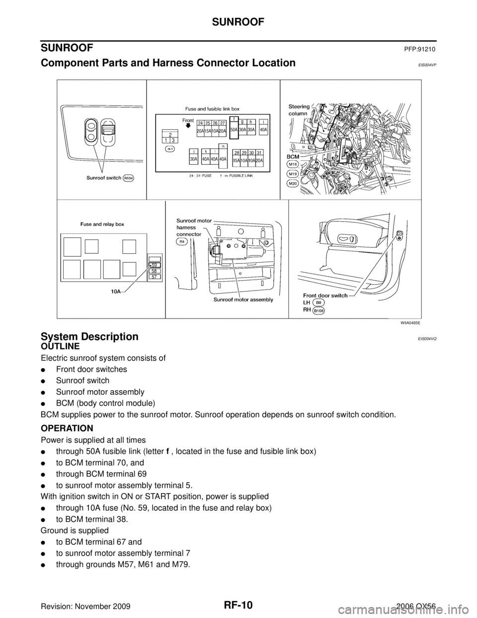
SUNROOFPFP:91210
Component Parts and Harness Connector LocationEIS004VP
System DescriptionEIS004VQ
OUTLINE
Electric sunroof system consists of
�Front door switches
�Sunroof switch
�Sunroof motor assembly
�BCM (body control module)
BCM supplies power to the sunroof motor. Sunroof operation depends on sunroof switch condition.
OPERATION
Power is supplied at all times
�through 50A fusible link (letter f , located in the fuse and fusible link box)
�to BCM terminal 70, and
�through BCM terminal 69
�to sunroof motor assembly terminal 5.
With ignition switch in ON or START position, power is supplied
�through 10A fuse (No. 59, located in the fuse and relay box)
�to BCM terminal 38.
Ground is supplied
�to BCM terminal 67 and
�to sunroof motor assembly terminal 7
�through grounds M57, M61 and M79.
WIIA0465E

Revision: November 20092006 QX56
FUSE BLOCK-JUNCTION BOX (J/B)PFP:24350
Terminal ArrangementEKS00BNN
WKIA4690E")