Page 2436 of 3383
HEADLAMP (FOR USA)LT-29
C
DE
F
G H
I
J
L
M A
B
LT
Revision: November 2009 2006 QX56
Aiming AdjustmentEKS00B89
For details, refer to the regulations in your area.
NOTE:
If vehicle front body has been repaired and /or the headlamp assembly has been replaced, check headlamp
aiming.
HEADLAMP AIMING
NOTE:
�Before performing aiming adjustment, check the following:
–Confirm headlamp aiming switch is set to "0" (zero) position.
–Ensure all tires are inflated to correct pressure.
–Place vehicle and screen on level surface.
–Ensure there is no load in vehicle other than the driver (or equivalent weight placed in driver's position).
Coolant and engine oil filled to correct level, and fuel tank full.
–Confirm spare tire, jack and tools are properly stowed.
–Aim each headlamp individually and ensure other headlamp beam pattern is blocked from screen.
–Use adjusting screw to perform aiming adjustment
WKIA1859E
Page 2505 of 3383
LT-98
LIGHTING AND TURN SIGNAL SWITCH
Revision: November 20092006 QX56
LIGHTING AND TURN SIGNAL SWITCHPFP:25540
Removal and InstallationEKS00BA5
REMOVAL
1. Remove steering column cover.
2. While pressing tabs, pull lighting and turn signal switch toward
driver door and disconnect from the base.
INSTALLATION
Installation is in the reverse order of removal.
LKIA0013E
Page 2533 of 3383

LT-126
TRAILER TOW
Revision: November 20092006 QX56
TRAILER TOWPFP:93020
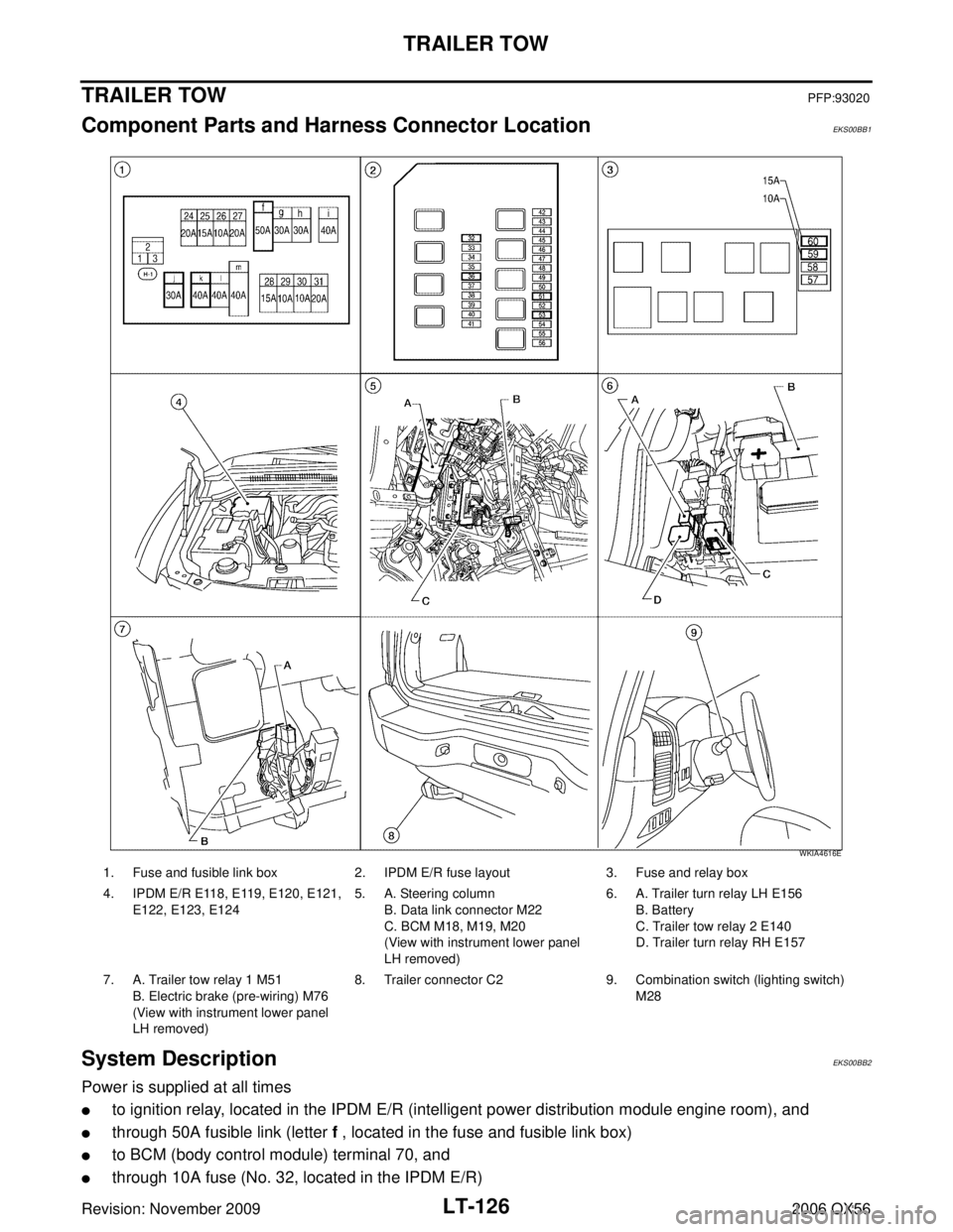
Component Parts and Harness Connector LocationEKS00BB1
System DescriptionEKS00BB2
Power is supplied at all times
�to ignition relay, located in the IPDM E/R (intelligent power distribution module engine room), and
�through 50A fusible link (letter f , located in the fuse and fusible link box)
�to BCM (body control module) terminal 70, and
�through 10A fuse (No. 32, located in the IPDM E/R)
1. Fuse and fusible link box2. IPDM E/R fuse layout 3. Fuse and relay box
4. IPDM E/R E118, E119, E120, E121, E122, E123, E124 5. A. Steering column
B. Data link connector M22
C. BCM M18, M19, M20
(View with instrument lower panel
LH removed) 6. A. Trailer turn relay LH E156
B. Battery
C. Trailer tow relay 2 E140
D. Trailer turn relay RH E157
7. A. Trailer tow relay 1 M51 B. Electric brake (pre-wiring) M76
(View with instrument lower panel
LH removed) 8. Trailer connector C2
9. Combination switch (lighting switch)
M28
WKIA4616E
Page 2534 of 3383

TRAILER TOWLT-127
C
DE
F
G H
I
J
L
M A
B
LT
Revision: November 2009 2006 QX56
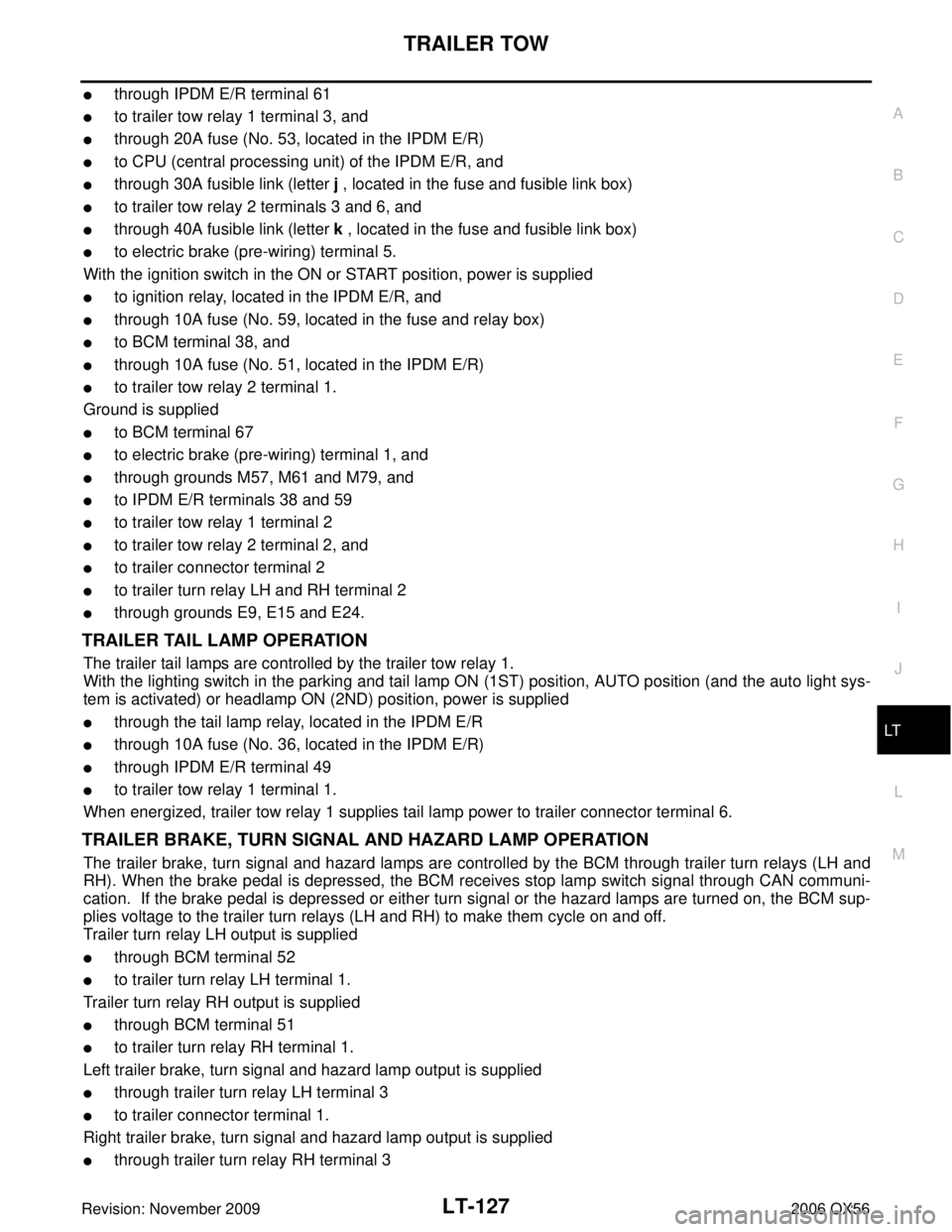
�through IPDM E/R terminal 61
�to trailer tow relay 1 terminal 3, and
�through 20A fuse (No. 53, located in the IPDM E/R)
�to CPU (central processing unit) of the IPDM E/R, and
�through 30A fusible link (letter j , located in the fuse and fusible link box)
�to trailer tow relay 2 terminals 3 and 6, and
�through 40A fusible link (letter k , located in the fuse and fusible link box)
�to electric brake (pre-wiring) terminal 5.
With the ignition switch in the ON or START position, power is supplied
�to ignition relay, located in the IPDM E/R, and
�through 10A fuse (No. 59, located in the fuse and relay box)
�to BCM terminal 38, and
�through 10A fuse (No. 51, located in the IPDM E/R)
�to trailer tow relay 2 terminal 1.
Ground is supplied
�to BCM terminal 67
�to electric brake (pre-wiring) terminal 1, and
�through grounds M57, M61 and M79, and
�to IPDM E/R terminals 38 and 59
�to trailer tow relay 1 terminal 2
�to trailer tow relay 2 terminal 2, and
�to trailer connector terminal 2
�to trailer turn relay LH and RH terminal 2
�through grounds E9, E15 and E24.
TRAILER TAIL LAMP OPERATION
The trailer tail lamps are controlled by the trailer tow relay 1.
With the lighting switch in the parking and tail lamp ON (1ST) position, AUTO position (and the auto light sys-
tem is activated) or headlamp ON (2ND) position, power is supplied
�through the tail lamp relay, located in the IPDM E/R
�through 10A fuse (No. 36, located in the IPDM E/R)
�through IPDM E/R terminal 49
�to trailer tow relay 1 terminal 1.
When energized, trailer tow relay 1 supplies tail lamp power to trailer connector terminal 6.
TRAILER BRAKE, TURN SIGNAL AND HAZARD LAMP OPERATION
The trailer brake, turn signal and hazard lamps are controlled by the BCM through trailer turn relays (LH and
RH). When the brake pedal is depressed, the BCM receives stop lamp switch signal through CAN communi-
cation. If the brake pedal is depressed or either turn signal or the hazard lamps are turned on, the BCM sup-
plies voltage to the trailer turn relays (LH and RH) to make them cycle on and off.
Trailer turn relay LH output is supplied
�through BCM terminal 52
�to trailer turn relay LH terminal 1.
Trailer turn relay RH output is supplied
�through BCM terminal 51
�to trailer turn relay RH terminal 1.
Left trailer brake, turn signal and hazard lamp output is supplied
�through trailer turn relay LH terminal 3
�to trailer connector terminal 1.
Right trailer brake, turn signal and hazard lamp output is supplied
�through trailer turn relay RH terminal 3
Page 2535 of 3383
LT-128
TRAILER TOW
Revision: November 20092006 QX56
�to trailer connector terminal 4.
TRAILER BRAKE OPERATION
The trailer brake is controlled by the electric brake. The electric brake receives stop lamp switch signal at elec-
tric brake (pre-wiring) terminal 2 when the brake pedal is depressed.
When the brake pedal is depressed, power is supplied by the electric brake
�through electric brake (pre-wiring) terminal 3
�to trailer connector terminal 3.
TRAILER POWER SUPPLY OPERATION
The trailer power supply is controlled by the trailer tow relay 2.
When the ignition switch is in the ON or START position, power is supplied
�through 10A fuse (No. 51, located in the IPDM E/R)
�through IPDM E/R terminal 16
�to trailer tow relay 2 terminal 1.
When energized, the trailer tow relay 2 supplies power
�through trailer tow relay 2 terminals 5 and 7
�to trailer connector terminal 5.
Page 2536 of 3383
TRAILER TOWLT-129
C
DE
F
G H
I
J
L
M A
B
LT
Revision: November 2009 2006 QX56
SchematicEKS00BB3
WKWA3664E
Page 2537 of 3383
LT-130
TRAILER TOW
Revision: November 20092006 QX56
Wiring Diagram — T/TOW —EKS00BB4
WKWA3665E
Page 2538 of 3383
TRAILER TOWLT-131
C
DE
F
G H
I
J
L
M A
B
LT
Revision: November 2009 2006 QX56
WKWA3666E