2006 INFINITI QX56 sensor
[x] Cancel search: sensorPage 1188 of 3383
REAR SONAR SYSTEMDI-67
C
DE
F
G H
I
J
L
M A
B
DI
Revision: November 2009 2006 QX56
REQUESTING FAULT CODES MODE
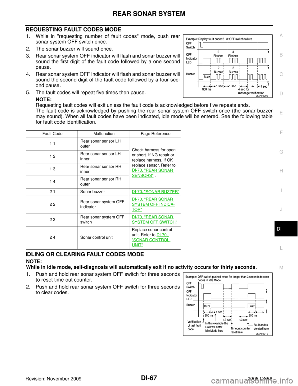
1. While in "requesting number of fault codes" mode, push rear
sonar system OFF switch once.
2. The sonar buzzer will sound once.
3. Rear sonar system OFF indicator will flash and sonar buzzer will sound the first digit of the fault code followed by a one second
pause.
4. Rear sonar system OFF indicator will flash and sonar buzzer will sound the second digit of the fault code followed by a four sec-
ond pause.
5. The fault codes will repeat five times then pause. NOTE:
Requesting fault codes will exit unless the fault code is acknowledged before five repeats ends.
The fault code is acknowledged by pushing the rear sonar system OFF switch once (the sonar buzzer
may sound). When all fault codes have been indicated, idle mode will be entered. See the following table
for fault code identification.
IDLING OR CLEARING FAULT CODES MODE
NOTE:
While in idle mode, self-diagnosis will automatically exit if no activity occurs for thirty seconds.
1. Push and hold rear sonar system OFF switch for three secondsto reset time-out counter.
2. Push and hold rear sonar system OFF switch for three seconds to clear codes.
Fault Code MalfunctionPage Reference
1 1 Rear sonar sensor LH
outer
Check harness for open
or short. If NG repair or
replace harness. If OK
replace sensor. Refer to
DI-70, "
REAR SONAR
SENSORS" .
1 2
Rear sonar sensor LH
inner
1 3 Rear sonar sensor RH
inner
1 4 Rear sonar sensor RH
outer
2 1 Sonar buzzer DI-70, "
SONAR BUZZER"
2 2Rear sonar system OFF
indicator DI-70, "
REAR SONAR
SYSTEM OFF INDICA-
TOR"
2 3
Rear sonar system OFF
switch DI-70, "REAR SONAR
SYSTEM OFF SWITCH"
2 4
Sonar control unit Replace sonar control
unit. Refer to DI-70, "SONAR CONTROL
UNIT"
LKIA0390E
LKIA0391E
Page 1190 of 3383
REAR SONAR SYSTEMDI-69
C
DE
F
G H
I
J
L
M A
B
DI
Revision: November 2009 2006 QX56
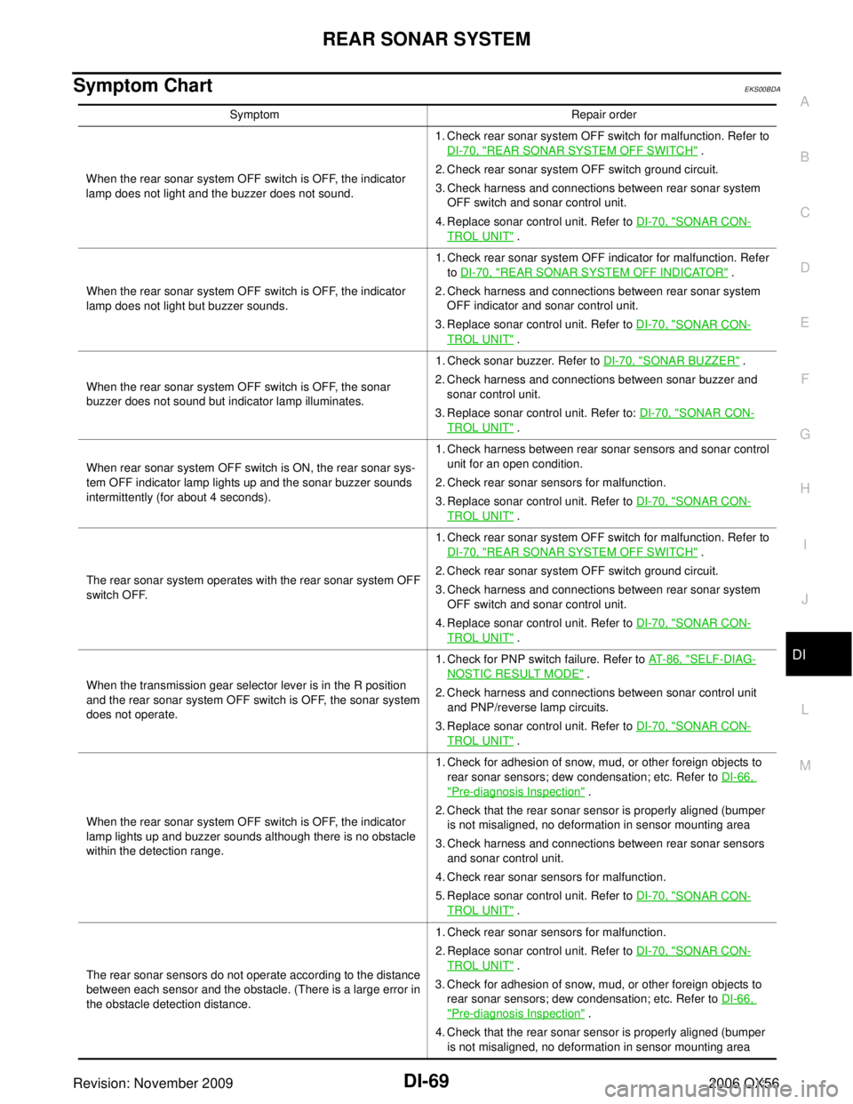
Symptom Chart EKS00BDA
SymptomRepair order
When the rear sonar system OFF switch is OFF, the indicator
lamp does not light and the buzzer does not sound. 1. Check rear sonar system OFF switch for malfunction. Refer to
DI-70, "
REAR SONAR SYSTEM OFF SWITCH" .
2. Check rear sonar system OFF switch ground circuit.
3. Check harness and connections between rear sonar system OFF switch and sonar control unit.
4. Replace sonar control unit. Refer to DI-70, "
SONAR CON-
TROL UNIT" .
When the rear sonar system OFF switch is OFF, the indicator
lamp does not light but buzzer sounds. 1. Check rear sonar system OFF indicator for malfunction. Refer
to DI-70, "
REAR SONAR SYSTEM OFF INDICATOR" .
2. Check harness and connections between rear sonar system OFF indicator and sonar control unit.
3. Replace sonar control unit. Refer to DI-70, "
SONAR CON-
TROL UNIT" .
When the rear sonar system OFF switch is OFF, the sonar
buzzer does not sound but indicator lamp illuminates. 1. Check sonar buzzer. Refer to
DI-70, "
SONAR BUZZER" .
2. Check harness and connections between sonar buzzer and sonar control unit.
3. Replace sonar control unit. Refer to: DI-70, "
SONAR CON-
TROL UNIT" .
When rear sonar system OFF switch is ON, the rear sonar sys-
tem OFF indicator lamp lights up and the sonar buzzer sounds
intermittently (for about 4 seconds). 1. Check harness between rear sonar sensors and sonar control
unit for an open condition.
2. Check rear sonar sensors for malfunction.
3. Replace sonar control unit. Refer to DI-70, "
SONAR CON-
TROL UNIT" .
The rear sonar system operates with the rear sonar system OFF
switch OFF. 1. Check rear sonar system OFF switch for malfunction. Refer to
DI-70, "
REAR SONAR SYSTEM OFF SWITCH" .
2. Check rear sonar system OFF switch ground circuit.
3. Check harness and connections between rear sonar system OFF switch and sonar control unit.
4. Replace sonar control unit. Refer to DI-70, "
SONAR CON-
TROL UNIT" .
When the transmission gear selector lever is in the R position
and the rear sonar system OFF switch is OFF, the sonar system
does not operate. 1. Check for PNP switch failure. Refer to
AT-86, "
SELF-DIAG-
NOSTIC RESULT MODE" .
2. Check harness and connections between sonar control unit and PNP/reverse lamp circuits.
3. Replace sonar control unit. Refer to DI-70, "
SONAR CON-
TROL UNIT" .
When the rear sonar system OFF switch is OFF, the indicator
lamp lights up and buzzer sounds although there is no obstacle
within the detection range. 1. Check for adhesion of snow, mud, or other foreign objects to
rear sonar sensors; dew condensation; etc. Refer to DI-66,
"Pre-diagnosis Inspection" .
2. Check that the rear sonar sensor is properly aligned (bumper is not misaligned, no deformation in sensor mounting area
3. Check harness and connections between rear sonar sensors and sonar control unit.
4. Check rear sonar sensors for malfunction.
5. Replace sonar control unit. Refer to DI-70, "
SONAR CON-
TROL UNIT" .
The rear sonar sensors do not operate according to the distance
between each sensor and the obstacle. (There is a large error in
the obstacle detection distance. 1. Check rear sonar sensors for malfunction.
2. Replace sonar control unit. Refer to
DI-70, "
SONAR CON-
TROL UNIT" .
3. Check for adhesion of snow, mud, or other foreign objects to rear sonar sensors; dew condensation; etc. Refer to DI-66,
"Pre-diagnosis Inspection" .
4. Check that the rear sonar sensor is properly aligned (bumper is not misaligned, no deformation in sensor mounting area
Page 1191 of 3383
DI-70
REAR SONAR SYSTEM
Revision: November 20092006 QX56
Component InspectionEKS00BDB
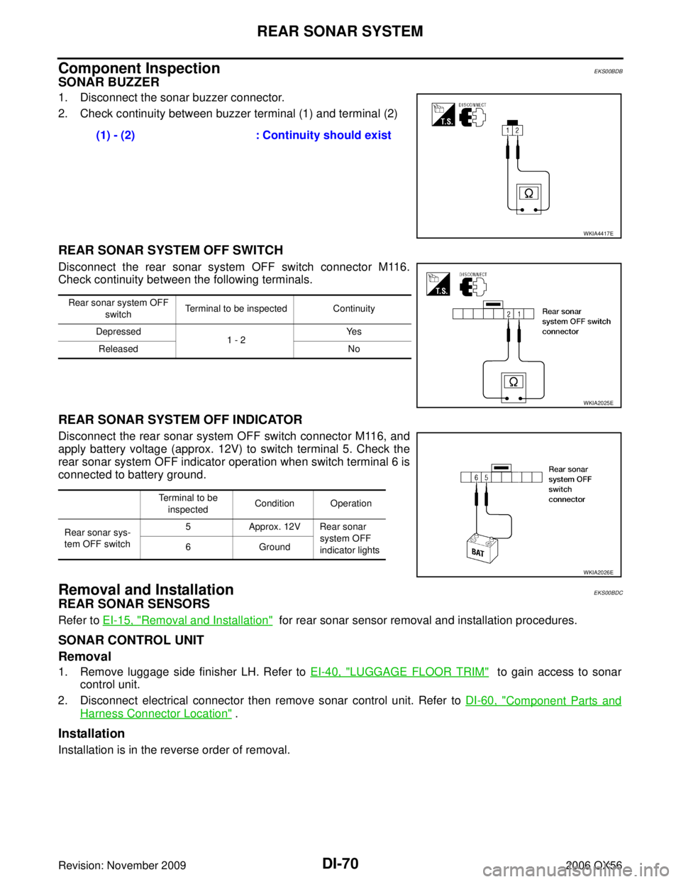
SONAR BUZZER
1. Disconnect the sonar buzzer connector.
2. Check continuity between buzzer terminal (1) and terminal (2)
REAR SONAR SYSTEM OFF SWITCH
Disconnect the rear sonar system OFF switch connector M116.
Check continuity between the following terminals.
REAR SONAR SYSTEM OFF INDICATOR
Disconnect the rear sonar system OFF switch connector M116, and
apply battery voltage (approx. 12V) to switch terminal 5. Check the
rear sonar system OFF indicator operation when switch terminal 6 is
connected to battery ground.
Removal and InstallationEKS00BDC
REAR SONAR SENSORS
Refer to EI-15, "Removal and Installation" for rear sonar sensor removal and installation procedures.
SONAR CONTROL UNIT
Removal
1. Remove luggage side finisher LH. Refer to EI-40, "LUGGAGE FLOOR TRIM" to gain access to sonar
control unit.
2. Disconnect electrical connector then remove sonar control unit. Refer to DI-60, "
Component Parts and
Harness Connector Location" .
Installation
Installation is in the reverse order of removal.(1) - (2)
: Continuity should exist
WKIA4417E
Rear sonar system OFF
switch Terminal to be inspected Continuity
Depressed 1 - 2Ye s
Released No
WKIA2025E
Terminal to be
inspected Condition Operation
Rear sonar sys-
tem OFF switch 5 Approx. 12V Rear sonar
system OFF
indicator lights
6
Ground
WKIA2026E
Page 1212 of 3383

EC-1
ENGINE CONTROL SYSTEM
B ENGINE
CONTENTS
C
DE
F
G H
I
J
K L
M
SECTION
A
EC
Revision: November 2009 2006 QX56
INDEX FOR DTC ...................................................
..... 8
DTC No. Index .................................................... ..... 8
Alphabetical Index ............................................... ... 12
PRECAUTIONS ..................................................... ... 16
Precautions for Supplemental Restraint System
(SRS) “AIR BAG” and “SEAT BELT PRE-TEN-
SIONER” ............................................................. ... 16
On Board Diagnostic (OBD) System of Engine and
A/T ....................................................................... ... 16
Precaution ........................................................... ... 16
PREPARATION ...................................................... ... 20
Special Service Tools .......................................... ... 20
Commercial Service Tools ................................... ... 22
ENGINE CONTROL SYSTEM ............................... ... 23
System Diagram .................................................. ... 23
Multiport Fuel Injection (MFI) System ................. ... 24
Electronic Ignition (EI) System ............................ ... 26
Fuel Cut Control (at No Load and High Engine
Speed) ................................................................. ... 27
AIR CONDITIONING CUT CONTROL .................. ... 28
Input/Output Signal Chart .................................... ... 28
System Description ............................................. ... 28
AUTOMATIC SPEED CONTROL DEVICE (ASCD) ... 29
System Description ............................................. ... 29
Component Description ....................................... ... 30
CAN COMMUNICATION ....................................... ... 31
System Description ............................................. ... 31
EVAPORATIVE EMISSION SYSTEM .................... ... 32
Description .......................................................... ... 32
Component Inspection ........................................ ... 35
Removal and Installation ..................................... ... 36
How to Detect Fuel Vapor Leakage .................... ... 37
ON BOARD REFUELING VAPOR RECOVERY
(ORVR) ................................................................... ... 39
System Description ............................................. ... 39
Diagnostic Procedure .......................................... ... 40
Component Inspection ........................................ ... 43
POSITIVE CRANKCASE VENTILATION .............. ... 45
Description .......................................................... ... 45
Component Inspection ........................................ ... 45IVIS (INFINITI VEHICLE IMMOBILIZER SYSTEM-
NATS) .....................................................................
... 47
Description ........................................................... ... 47
ON BOARD DIAGNOSTIC (OBD) SYSTEM ......... ... 48
Introduction .......................................................... ... 48
Two Trip Detection Logic ..................................... ... 48
Emission-related Diagnostic Information ............. ... 49
Malfunction Indicator Lamp (MIL) ........................ ... 63
OBD System Operation Chart ............................. ... 65
BASIC SERVICE PROCEDURE ............................ ... 71
Basic Inspection ..................................................... 71
Idle Speed and Ignition Timing Check ................. ... 76
VIN Registration ..................................................... 77
Accelerator Pedal Released Position Learning ... ... 78
Throttle Valve Closed Position Learning .............. ... 78
Idle Air Volume Learning ..................................... ... 78
Fuel Pressure Check .............................................. 80
TROUBLE DIAGNOSIS ......................................... ... 83
Trouble Diagnosis Introduction ............................ ... 83
DTC Inspection Priority Chart .............................. ... 89
Fail-safe Chart ..................................................... ... 91
Symptom Matrix Chart ......................................... ... 92
Engine Control Component Parts Location ......... ... 96
Vacuum Hose Drawing ........................................ .102
Circuit Diagram .................................................... .103
ECM Harness Connector Terminal Layout .......... .105
ECM Terminals and Reference Value .................. .105
CONSULT-II Function (ENGINE) ......................... .114
Generic Scan Tool (GST) Function ...................... .127
CONSULT-II Reference Value in Data Monitor .... .129
Major Sensor Reference Graph in Data Monitor
Mode .................................................................... .132
TROUBLE DIAGNOSIS - SPECIFICATION VALUE .134
Description ........................................................... .134
Testing Condition ................................................. .134
Inspection Procedure ........................................... .134
Diagnostic Procedure .......................................... .135
TROUBLE DIAGNOSIS FOR INTERMITTENT INCI-
DENT ...................................................................... .144
Page 1213 of 3383

EC-2Revision: November 20092006 QX56
Description ...........................................................
.144
Diagnostic Procedure .......................................... .144
POWER SUPPLY AND GROUND CIRCUIT .......... .145
Wiring Diagram .................................................... .145
Diagnostic Procedure .......................................... .146
Ground Inspection ............................................... .150
DTC U1000, U1001 CAN COMMUNICATION LINE .151
Description ........................................................... .151
On Board Diagnosis Logic ................................... .151
DTC Confirmation Procedure .............................. .151
Wiring Diagram .................................................... .152
Diagnostic Procedure .......................................... .153
DTC U1010 CAN COMMUNICATION .................... .154
Description ........................................................... .154
On Board Diagnosis Logic ................................... .154
DTC Confirmation Procedure .............................. .154
Diagnostic Procedure .......................................... .155
DTC P0031, P0032, P0051, P0052 A/F SENSOR 1
HEATER ................................................................. .156
Description ........................................................... .156
CONSULT-II Reference Value in Data Monitor Mode .156
On Board Diagnosis Logic ................................... .156
DTC Confirmation Procedure .............................. .156
Wiring Diagram .................................................... .157
Diagnostic Procedure .......................................... .160
Component Inspection ......................................... .162
Removal and Installation ..................................... .162
DTC P0037, P0038, P0057, P0058 HO2S2 HEATER .163
Description ........................................................... .163
CONSULT-II Reference Value in Data Monitor Mode .163
On Board Diagnosis Logic ................................... .163
DTC Confirmation Procedure .............................. .164
Wiring Diagram .................................................... .165
Diagnostic Procedure .......................................... .168
Component Inspection ......................................... .170
Removal and Installation ..................................... .170
DTC P0101 MAF SENSOR .................................... .171
Component Description ....................................... .171
CONSULT-II Reference Value in Data Monitor Mode .171
On Board Diagnosis Logic ................................... .171
DTC Confirmation Procedure .............................. .172
Overall Function Check ....................................... .173
Wiring Diagram .................................................... .174
Diagnostic Procedure .......................................... .175
Component Inspection ......................................... .178
Removal and Installation ..................................... .179
DTC P0102, P0103 MAF SENSOR ........................ .180
Component Description ....................................... .180
CONSULT-II Reference Value in Data Monitor Mode .180
On Board Diagnosis Logic ................................... .180
DTC Confirmation Procedure .............................. .181
Wiring Diagram .................................................... .182
Diagnostic Procedure .......................................... .183
Component Inspection ......................................... .186
Removal and Installation ..................................... .187DTC P0112, P0113 IAT SENSOR ...........................
.188
Component Description ....................................... .188
On Board Diagnosis Logic ................................... .188
DTC Confirmation Procedure ............................... .188
Wiring Diagram .................................................... .189
Diagnostic Procedure ........................................... .190
Component Inspection ......................................... .191
Removal and Installation ...................................... .191
DTC P0117, P0118 ECT SENSOR ......................... .192
Component Description ....................................... .192
On Board Diagnosis Logic ................................... .192
DTC Confirmation Procedure ............................... .193
Wiring Diagram .................................................... .194
Diagnostic Procedure ........................................... .195
Component Inspection ......................................... .196
Removal and Installation ...................................... .197
DTC P0122, P0123 TP SENSOR ........................... .198
Component Description ....................................... .198
CONSULT-II Reference Value in Data Monitor Mode .198
On Board Diagnosis Logic ................................... .198
DTC Confirmation Procedure ............................... .199
Wiring Diagram .................................................... .200
Diagnostic Procedure ........................................... .201
Component Inspection ......................................... .204
Removal and Installation ...................................... .204
DTC P0125 ECT SENSOR ..................................... .205
Component Description ....................................... .205
On Board Diagnosis Logic ................................... .205
DTC Confirmation Procedure ............................... .206
Diagnostic Procedure ........................................... .206
Component Inspection ......................................... .207
Removal and Installation ...................................... .207
DTC P0127 IAT SENSOR ....................................... .208
Component Description ....................................... .208
On Board Diagnosis Logic ................................... .208
DTC Confirmation Procedure ............................... .208
Diagnostic Procedure ........................................... .209
Component Inspection ......................................... .210
Removal and Installation ...................................... .210
DTC P0128 THERMOSTAT FUNCTION ................ .211
On Board Diagnosis Logic ................................... .211
DTC Confirmation Procedure ............................... .211
Diagnostic Procedure ........................................... .211
Component Inspection ......................................... .212
Removal and Installation ...................................... .212
DTC P0130, P0150 A/F SENSOR 1 ....................... .213
Component Description ....................................... .213
CONSULT-II Reference Value in Data Monitor Mode .213
On Board Diagnosis Logic ................................... .213
DTC Confirmation Procedure ............................... .213
Overall Function Check ........................................ .214
Wiring Diagram .................................................... .216
Diagnostic Procedure ........................................... .219
Removal and Installation ...................................... .222
DTC P0131, P0151 A/F SENSOR 1 ....................... .223
Component Description ....................................... .223
CONSULT-II Reference Value in Data Monitor Mode
Page 1214 of 3383
EC-3
C
DE
F
G H
I
J
K L
M
EC A
Revision: November 2009 2006 QX56
. 223
On Board Diagnosis Logic .................................. . 223
DTC Confirmation Procedure .............................. . 223
Wiring Diagram ................................................... . 225
Diagnostic Procedure .......................................... . 228
Removal and Installation ..................................... . 231
DTC P0132, P0152 A/F SENSOR 1 ...................... . 232
Component Description ....................................... . 232
CONSULT-II Reference Value in Data Monitor Mode . 232
On Board Diagnosis Logic .................................. . 232
DTC Confirmation Procedure .............................. . 232
Wiring Diagram ................................................... . 234
Diagnostic Procedure .......................................... . 237
Removal and Installation ..................................... . 240
DTC P0133, P0153 A/F SENSOR 1 ...................... . 241
Component Description ....................................... . 241
CONSULT-II Reference Value in Data Monitor Mode . 241
On Board Diagnosis Logic .................................. . 241
DTC Confirmation Procedure .............................. . 242
Wiring Diagram ................................................... . 244
Diagnostic Procedure .......................................... . 247
Removal and Installation ..................................... . 252
DTC P0137, P0157 HO2S2 ................................... . 253
Component Description ....................................... . 253
CONSULT-II Reference Value in Data Monitor Mode . 253
On Board Diagnosis Logic .................................. . 253
DTC Confirmation Procedure .............................. . 254
Overall Function Check ....................................... . 254
Wiring Diagram ................................................... . 256
Diagnostic Procedure .......................................... . 259
Component Inspection ........................................ . 262
Removal and Installation ..................................... . 263
DTC P0138, P0158 HO2S2 ................................... . 264
Component Description ....................................... . 264
CONSULT-II Reference Value in Data Monitor Mode . 264
On Board Diagnosis Logic .................................. . 264
DTC Confirmation Procedure .............................. . 265
Overall Function Check ....................................... . 266
Wiring Diagram ................................................... . 267
Diagnostic Procedure .......................................... . 270
Component Inspection ........................................ . 275
Removal and Installation ..................................... . 276
DTC P0139, P0159 HO2S2 ................................... . 277
Component Description ....................................... . 277
CONSULT-II Reference Value in Data Monitor Mode . 277
On Board Diagnosis Logic .................................. . 277
DTC Confirmation Procedure .............................. . 278
Overall Function Check ....................................... . 278
Wiring Diagram ................................................... . 280
Diagnostic Procedure .......................................... . 283
Component Inspection ........................................ . 286
Removal and Installation ..................................... . 287
DTC P0171, P0174 FUEL INJECTION SYSTEM
FUNCTION ............................................................. . 288On Board Diagnosis Logic ...................................
.288
DTC Confirmation Procedure .............................. .288
Wiring Diagram .................................................... .290
Diagnostic Procedure .......................................... .294
DTC P0172, P0175 FUEL INJECTION SYSTEM
FUNCTION ............................................................. .299
On Board Diagnosis Logic ................................... .299
DTC Confirmation Procedure .............................. .299
Wiring Diagram .................................................... .301
Diagnostic Procedure .......................................... .305
DTC P0181 FTT SENSOR ..................................... .309
Component Description ....................................... .309
On Board Diagnosis Logic ................................... .309
DTC Confirmation Procedure .............................. .309
Wiring Diagram .................................................... .311
Diagnostic Procedure .......................................... .312
Component Inspection ......................................... .314
Removal and Installation ..................................... .314
DTC P0182, P0183 FTT SENSOR ......................... .315
Component Description ....................................... .315
On Board Diagnosis Logic ................................... .315
DTC Confirmation Procedure .............................. .315
Wiring Diagram .................................................... .316
Diagnostic Procedure .......................................... .317
Component Inspection ......................................... .319
Removal and Installation ..................................... .319
DTC P0222, P0223 TP SENSOR ........................... .320
Component Description ....................................... .320
CONSULT-II Reference Value in Data Monitor Mode .320
On Board Diagnosis Logic ................................... .320
DTC Confirmation Procedure .............................. .321
Wiring Diagram .................................................... .322
Diagnostic Procedure .......................................... .323
Component Inspection ......................................... .326
Removal and Installation ..................................... .326
DTC P0300 - P0308 MULTIPLE CYLINDER MIS-
FIRE, NO. 1 - 8 CYLINDER MISFIRE .................... .327
On Board Diagnosis Logic ................................... .327
DTC Confirmation Procedure .............................. .327
Diagnostic Procedure .......................................... .328
DTC P0327, P0328, P0332, P0333 KS .................. .335
Component Description ....................................... .335
On Board Diagnosis Logic ................................... .335
DTC Confirmation Procedure .............................. .335
Wiring Diagram .................................................... .336
Diagnostic Procedure .......................................... .337
Component Inspection ......................................... .339
Removal and Installation ..................................... .339
DTC P0335 CKP SENSOR (POS) ......................... .340
Component Description ....................................... .340
CONSULT-II Reference Value in Data Monitor Mode .340
On Board Diagnosis Logic ................................... .340
DTC Confirmation Procedure .............................. .340
Wiring Diagram .................................................... .342
Diagnostic Procedure .......................................... .343
Component Inspection ......................................... .346
Removal and Installation ..................................... .346
Page 1215 of 3383

EC-4Revision: November 20092006 QX56
DTC P0340 CMP SENSOR (PHASE) ....................
.347
Component Description ....................................... .347
On Board Diagnosis Logic ................................... .347
DTC Confirmation Procedure .............................. .347
Wiring Diagram .................................................... .349
Diagnostic Procedure .......................................... .350
Component Inspection ......................................... .353
Removal and Installation ..................................... .353
DTC P0420, P0430 THREE WAY CATALYST FUNC-
TION ....................................................................... .354
On Board Diagnosis Logic ................................... .354
DTC Confirmation Procedure .............................. .354
Overall Function Check ....................................... .355
Diagnostic Procedure .......................................... .356
DTC P0441 EVAP CONTROL SYSTEM ................ .360
System Description .............................................. .360
On Board Diagnosis Logic ................................... .360
DTC Confirmation Procedure .............................. .360
Overall Function Check ....................................... .361
Diagnostic Procedure .......................................... .362
DTC P0442 EVAP CONTROL SYSTEM ................ .365
On Board Diagnosis Logic ................................... .365
DTC Confirmation Procedure .............................. .366
Diagnostic Procedure .......................................... .367
DTC P0443 EVAP CANISTER PURGE VOLUME
CONTROL SOLENOID VALVE .............................. .373
Description ........................................................... .373
CONSULT-II Reference Value in Data Monitor Mode .373
On Board Diagnosis Logic ................................... .374
DTC Confirmation Procedure .............................. .374
Wiring Diagram .................................................... .375
Diagnostic Procedure .......................................... .377
Component Inspection ......................................... .380
Removal and Installation ..................................... .380
DTC P0444, P0445 EVAP CANISTER PURGE VOL-
UME CONTROL SOLENOID VALVE ..................... .381
Description ........................................................... .381
CONSULT-II Reference Value in Data Monitor Mode .381
On Board Diagnosis Logic ................................... .382
DTC Confirmation Procedure .............................. .382
Wiring Diagram .................................................... .383
Diagnostic Procedure .......................................... .385
Component Inspection ......................................... .386
Removal and Installation ..................................... .387
DTC P0447 EVAP CANISTER VENT CONTROL
VALVE .................................................................... .388
Component Description ....................................... .388
CONSULT-II Reference Value in Data Monitor Mode .388
On Board Diagnosis Logic ................................... .388
DTC Confirmation Procedure .............................. .389
Wiring Diagram .................................................... .390
Diagnostic Procedure .......................................... .391
Component Inspection ......................................... .393
DTC P0448 EVAP CANISTER VENT CONTROL
VALVE .................................................................... .395
Component Description ....................................... .395CONSULT-II Reference Value in Data Monitor Mode
.395
On Board Diagnosis Logic ................................... .395
DTC Confirmation Procedure ............................... .396
Wiring Diagram .................................................... .397
Diagnostic Procedure ........................................... .398
Component Inspection ......................................... .400
DTC P0451 EVAP CONTROL SYSTEM PRESSURE
SENSOR ................................................................. .402
Component Description ....................................... .402
CONSULT-II Reference Value in Data Monitor Mode .402
On Board Diagnosis Logic ................................... .402
DTC Confirmation Procedure ............................... .403
Diagnostic Procedure ........................................... .403
Component Inspection ......................................... .404
DTC P0452 EVAP CONTROL SYSTEM PRESSURE
SENSOR ................................................................. .405
Component Description ....................................... .405
CONSULT-II Reference Value in Data Monitor Mode .405
On Board Diagnosis Logic ................................... .405
DTC Confirmation Procedure ............................... .406
Wiring Diagram .................................................... .407
Diagnostic Procedure ........................................... .408
Component Inspection ......................................... .410
DTC P0453 EVAP CONTROL SYSTEM PRESSURE
SENSOR ................................................................. .411
Component Description ....................................... .411
CONSULT-II Reference Value in Data Monitor Mode .411
On Board Diagnosis Logic ................................... .411
DTC Confirmation Procedure ............................... .412
Wiring Diagram .................................................... .413
Diagnostic Procedure ........................................... .414
Component Inspection ......................................... .418
DTC P0455 EVAP CONTROL SYSTEM ................ .419
On Board Diagnosis Logic ................................... .419
DTC Confirmation Procedure ............................... .420
Diagnostic Procedure ........................................... .421
DTC P0456 EVAP CONTROL SYSTEM ................ .427
On Board Diagnosis Logic ................................... .427
DTC Confirmation Procedure ............................... .428
Overall Function Check ........................................ .429
Diagnostic Procedure ........................................... .430
DTC P0460 FUEL LEVEL SENSOR ...................... .436
Component Description ....................................... .436
On Board Diagnosis Logic ................................... .436
DTC Confirmation Procedure ............................... .436
Diagnostic Procedure ........................................... .437
Removal and Installation ...................................... .437
DTC P0461 FUEL LEVEL SENSOR ...................... .438
Component Description ....................................... .438
On Board Diagnosis Logic ................................... .438
Overall Function Check ........................................ .438
Diagnostic Procedure ........................................... .439
Removal and Installation ...................................... .439
DTC P0462, P0463 FUEL LEVEL SENSOR CIR-
CUIT ........................................................................ .440
Page 1216 of 3383
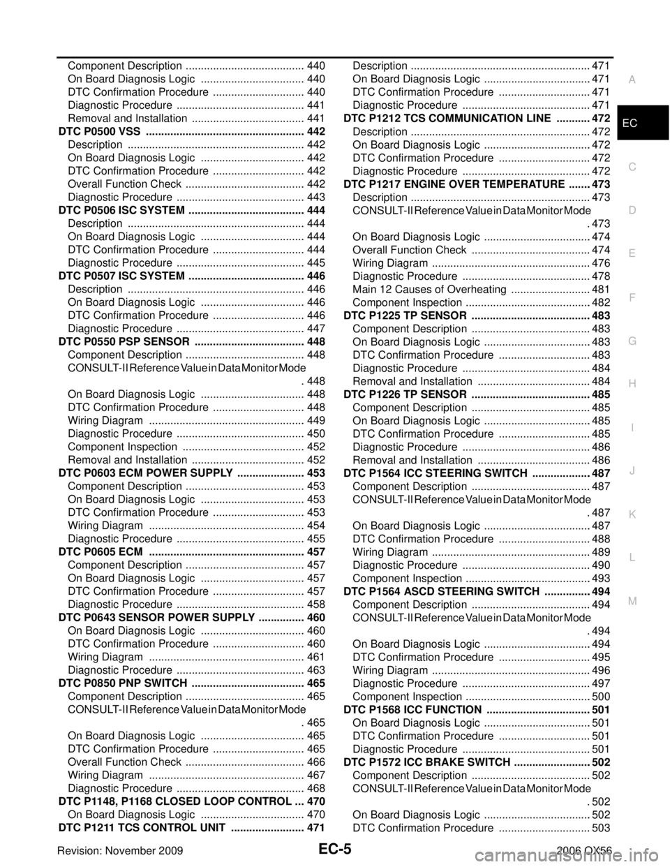
EC-5
C
DE
F
G H
I
J
K L
M
EC A
Revision: November 2009 2006 QX56
Component Description .......................................
. 440
On Board Diagnosis Logic .................................. . 440
DTC Confirmation Procedure .............................. . 440
Diagnostic Procedure .......................................... . 441
Removal and Installation ..................................... . 441
DTC P0500 VSS .................................................... . 442
Description .......................................................... . 442
On Board Diagnosis Logic .................................. . 442
DTC Confirmation Procedure .............................. . 442
Overall Function Check ....................................... . 442
Diagnostic Procedure .......................................... . 443
DTC P0506 ISC SYSTEM ...................................... . 444
Description .......................................................... . 444
On Board Diagnosis Logic .................................. . 444
DTC Confirmation Procedure .............................. . 444
Diagnostic Procedure .......................................... . 445
DTC P0507 ISC SYSTEM ...................................... . 446
Description .......................................................... . 446
On Board Diagnosis Logic .................................. . 446
DTC Confirmation Procedure .............................. . 446
Diagnostic Procedure .......................................... . 447
DTC P0550 PSP SENSOR .................................... . 448
Component Description ....................................... . 448
CONSULT-II Reference Value in Data Monitor Mode . 448
On Board Diagnosis Logic .................................. . 448
DTC Confirmation Procedure .............................. . 448
Wiring Diagram ................................................... . 449
Diagnostic Procedure .......................................... . 450
Component Inspection ........................................ . 452
Removal and Installation ..................................... . 452
DTC P0603 ECM POWER SUPPLY ...................... . 453
Component Description ....................................... . 453
On Board Diagnosis Logic .................................. . 453
DTC Confirmation Procedure .............................. . 453
Wiring Diagram ................................................... . 454
Diagnostic Procedure .......................................... . 455
DTC P0605 ECM ................................................... . 457
Component Description ....................................... . 457
On Board Diagnosis Logic .................................. . 457
DTC Confirmation Procedure .............................. . 457
Diagnostic Procedure .......................................... . 458
DTC P0643 SENSOR POWER SUPPLY ............... . 460
On Board Diagnosis Logic .................................. . 460
DTC Confirmation Procedure .............................. . 460
Wiring Diagram ................................................... . 461
Diagnostic Procedure .......................................... . 463
DTC P0850 PNP SWITCH ..................................... . 465
Component Description ....................................... . 465
CONSULT-II Reference Value in Data Monitor Mode . 465
On Board Diagnosis Logic .................................. . 465
DTC Confirmation Procedure .............................. . 465
Overall Function Check ....................................... . 466
Wiring Diagram ................................................... . 467
Diagnostic Procedure .......................................... . 468
DTC P1148, P1168 CLOSED LOOP CONTROL ... . 470
On Board Diagnosis Logic .................................. . 470
DTC P1211 TCS CONTROL UNIT ........................ . 471Description ...........................................................
.471
On Board Diagnosis Logic ................................... .471
DTC Confirmation Procedure .............................. .471
Diagnostic Procedure .......................................... .471
DTC P1212 TCS COMMUNICATION LINE ........... .472
Description ........................................................... .472
On Board Diagnosis Logic ................................... .472
DTC Confirmation Procedure .............................. .472
Diagnostic Procedure .......................................... .472
DTC P1217 ENGINE OVER TEMPERATURE ....... .473
Description ........................................................... .473
CONSULT-II Reference Value in Data Monitor Mode .473
On Board Diagnosis Logic ................................... .474
Overall Function Check ....................................... .474
Wiring Diagram .................................................... .476
Diagnostic Procedure .......................................... .478
Main 12 Causes of Overheating .......................... .481
Component Inspection ......................................... .482
DTC P1225 TP SENSOR ....................................... .483
Component Description ....................................... .483
On Board Diagnosis Logic ................................... .483
DTC Confirmation Procedure .............................. .483
Diagnostic Procedure .......................................... .484
Removal and Installation ..................................... .484
DTC P1226 TP SENSOR ....................................... .485
Component Description ....................................... .485
On Board Diagnosis Logic ................................... .485
DTC Confirmation Procedure .............................. .485
Diagnostic Procedure .......................................... .486
Removal and Installation ..................................... .486
DTC P1564 ICC STEERING SWITCH ................... .487
Component Description ....................................... .487
CONSULT-II Reference Value in Data Monitor Mode .487
On Board Diagnosis Logic ................................... .487
DTC Confirmation Procedure .............................. .488
Wiring Diagram .................................................... .489
Diagnostic Procedure .......................................... .490
Component Inspection ......................................... .493
DTC P1564 ASCD STEERING SWITCH ............... .494
Component Description ....................................... .494
CONSULT-II Reference Value in Data Monitor Mode .494
On Board Diagnosis Logic ................................... .494
DTC Confirmation Procedure .............................. .495
Wiring Diagram .................................................... .496
Diagnostic Procedure .......................................... .497
Component Inspection ......................................... .500
DTC P1568 ICC FUNCTION .................................. .501
On Board Diagnosis Logic ................................... .501
DTC Confirmation Procedure .............................. .501
Diagnostic Procedure .......................................... .501
DTC P1572 ICC BRAKE SWITCH ......................... .502
Component Description ....................................... .502
CONSULT-II Reference Value in Data Monitor Mode .502
On Board Diagnosis Logic ................................... .502
DTC Confirmation Procedure .............................. .503