Page 1133 of 3383
DI-12
COMBINATION METERS
Revision: November 20092006 QX56
Terminals and Reference Value for Combination MeterEKS00BBZ
Terminal
No. Wire
color Item Condition
Reference value (V)
(Approx.)
Ignition
switch Operation or condition
1O Ignition switch ACC or
ON ACC
— Battery voltage
8 Y/R Battery power supply OFF —Battery voltage
11 L C A N - H —— —
12 P CAN-L —— —
15 Y/L Fuel level sensor signal ——Refer to
DI-22, "
Fuel Level Sensor
Unit Inspection" .
16 B/P Fuel level sensor and oil
pressure sensor ground
ON
— 0V
17 B Ground OFF— 0V
18 BR Illumination control switch —Lighting switch ON Refer to
LT-158, "
ILLUMINATION
OPERATION BY LIGHTING
SWITCH" .
20 Y Oil pressure sensor sig-
nal
ON
— 0 - 5V
22 GR/L Oil pressure sensor refer-
ence voltage ON
— 5V
24 O/L Ignition switch ON or
START ON
— Battery voltage
Page 1140 of 3383

COMBINATION METERSDI-19
C
DE
F
G H
I
J
L
M A
B
DI
Revision: November 2009 2006 QX56
Symptom ChartEKS00BC4
Vehicle Speed Signal InspectionEKS00BC5
1. CHECK ABS ACTUATOR AND ELECTRIC UNIT (CONTROL UNIT) SELF-DIAGNOSIS
Refer to BRC-29, "
SELF-DIAGNOSIS" .
OK or NG
OK >> Replace the combination meter. Refer to IP-13, "COMBINATION METER" .
NG >> Perform "Diagnostic Procedure" for displayed DTC. Refer to BRC-11, "
TROUBLE DIAGNOSIS" .
Engine Oil Pressure Signal Inspection EKS00BC6
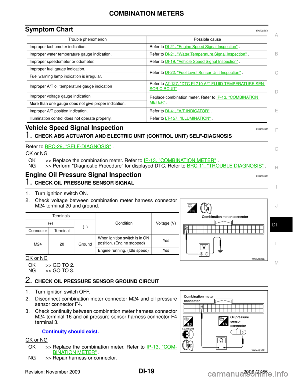
1. CHECK OIL PRESSURE SENSOR SIGNAL
1. Turn ignition switch ON.
2. Check voltage between combination meter harness connector M24 terminal 20 and ground.
OK or NG
OK >> GO TO 2.
NG >> GO TO 3.
2. CHECK OIL PRESSURE SENSOR GROUND CIRCUIT
1. Turn ignition switch OFF.
2. Disconnect combination meter connector M24 and oil pressure sensor connector F4.
3. Check continuity between combination meter harness connector M24 terminal 16 and oil pressure sensor harness connector F4
terminal 3.
OK or NG
OK >> Replace the combination meter. Refer to IP-13, "COM-
BINATION METER" .
NG >> Repair harness or connector.
Trouble phenomenon Possible cause
Improper tachometer indication. Refer to DI-21, "
Engine Speed Signal Inspection" .
Improper water temperature gauge indication. Refer to DI-21, "
Water Temperature Signal Inspection" .
Improper speedometer or odometer. Refer to DI-19, "
Vehicle Speed Signal Inspection" .
Improper fuel gauge indication. Refer to DI-22, "
Fuel Level Sensor Unit Inspection" .
Fuel warning lamp indication is irregular.
Improper A/T oil temperature gauge indication Refer to
AT-127, "
DTC P1710 A/T FLUID TEMPERATURE SEN-
SOR CIRCUIT" .
Improper voltage gauge indication Replace combination meter. Refer to IP-13, "
COMBINATION
METER" .
More than one gauge does not give proper indication.
Improper A/T position indication. Refer to DI-41, "
A/T INDICATOR" .
Illumination control does not operate properly. Refer to LT-157, "
ILLUMINATION" .
Terminals
Condition Voltage (V)
(+)
(– )
Connector Terminal
M24 20 Ground When ignition switch is in ON
position. (Engine stopped)
Ye s
Engine running. (Idle speed) Yes
WKIA1833E
Continuity should exist.
WKIA1837E
Page 1141 of 3383

DI-20
COMBINATION METERS
Revision: November 20092006 QX56
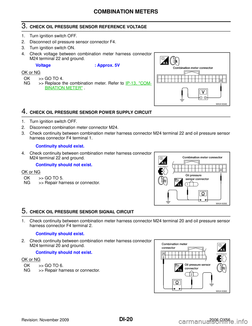
3. CHECK OIL PRESSURE SENSOR REFERENCE VOLTAGE
1. Turn ignition switch OFF.
2. Disconnect oil pressure sensor connector F4.
3. Turn ignition switch ON.
4. Check voltage between combination meter harness connector M24 terminal 22 and ground.
OK or NG
OK >> GO TO 4.
NG >> Replace the combination meter. Refer to IP-13, "
COM-
BINATION METER" .
4. CHECK OIL PRESSURE SENSOR POWER SUPPLY CIRCUIT
1. Turn ignition switch OFF.
2. Disconnect combination meter connector M24.
3. Check continuity between combination meter harness connector M24 terminal 22 and oil pressure sensor harness connector F4 terminal 1.
4. Check continuity between combination meter harness connector M24 terminal 22 and ground.
OK or NG
OK >> GO TO 5.
NG >> Repair harness or connector.
5. CHECK OIL PRESSURE SENSOR SIGNAL CIRCUIT
1. Check continuity between combination meter harness connector M24 terminal 20 and oil pressure sensor harness connector F4 terminal 2.
2. Check continuity between combination meter harness connector M24 terminal 20 and ground.
OK or NG
OK >> GO TO 6.
NG >> Repair harness or connector. Voltage
: Approx. 5V
WKIA1834E
Continuity should exist.
Continuity should not exist.
WKIA1835E
Continuity should exist.
Continuity should not exist.
WKIA1836E
Page 1142 of 3383
COMBINATION METERSDI-21
C
DE
F
G H
I
J
L
M A
B
DI
Revision: November 2009 2006 QX56
6. CHECK OIL PRESSURE SENSOR GROUND CIRCUIT
Check continuity between combination meter harness connector
M24 terminal 16 and ground.
OK or NG
OK >> Replace oil pressure sensor.
NG >> Repair harness or connector.
Water Temperature Signal Inspection EKS00BC7
1. CHECK ECM SELF-DIAGNOSIS
Perform ECM self-diagnosis. Refer to EC-118, "
SELF-DIAG RESULTS MODE" .
OK or NG
OK >> Replace the combination meter. Refer to IP-13, "COMBINATION METER" .
NG >> Perform "Diagnostic procedure" for displayed DTC. Refer to EC-83, "
TROUBLE DIAGNOSIS" .
Engine Speed Signal Inspection EKS00BC8
1. CHECK ECM SELF-DIAGNOSIS
Perform ECM self-diagnosis. Refer to EC-118, "
SELF-DIAG RESULTS MODE" .
OK or NG
OK >> Replace the combination meter. Refer to IP-13, "COMBINATION METER" .
NG >> Perform "Diagnostic procedure" for displayed DTC. Refer to EC-83, "
TROUBLE DIAGNOSIS" .
Continuity should not exist.
WKIA2685E
Page 1143 of 3383

DI-22
COMBINATION METERS
Revision: November 20092006 QX56
Fuel Level Sensor Unit InspectionEKS00BC9
FUEL LEVEL SENSOR UNIT
The following symptoms do not indicate a malfunction.
�Depending on vehicle position or driving circumstance, the fuel in the tank shifts and the indication may
fluctuate.
�If the vehicle is fueled with the ignition switch ON, the indication will update slowly.
�If the vehicle is tilted when the ignition switch is turned ON, fuel in the tank may flow to one direction
resulting in a change of reading.
LOW-FUEL WARNING LAMP
Depending on vehicle posture or driving circumstances, the fuel level in the tank varies, and the warning lamp
ON timing may be changed.
1. CHECK SELF-DIAGNOSIS
Perform the combination meter self-diagnosis. Refer to DI-13, "
SELF-DIAGNOSIS FUNCTION" .
OK or NG
OK >> GO TO 2.
NG >> Replace the combination meter. Refer to IP-13, "
COMBINATION METER" .
2. CHECK HARNESS CONNECTOR
1. Turn the ignition switch OFF.
2. Check combination meter and fuel level sensor unit and fuel pump terminals (meter-side, and harness- side) for poor connection.
OK or NG
OK >> GO TO 3.
NG >> Repair or replace terminals or connectors.
3. CHECK HARNESS CONNECTOR OUTPUT SIGNAL
1. Disconnect fuel level sensor unit and fuel pump connector.
2. Turn ignition switch ON.
3. Check voltage between combination meter harness connector M24 terminal 15 and ground.
OK or NG
OK >> GO TO 4.
NG >> Replace the combination meter. Refer to IP-13, "
COM-
BINATION METER" .
Battery voltage should exist.WKIA1816E
Page 1144 of 3383

COMBINATION METERSDI-23
C
DE
F
G H
I
J
L
M A
B
DI
Revision: November 2009 2006 QX56
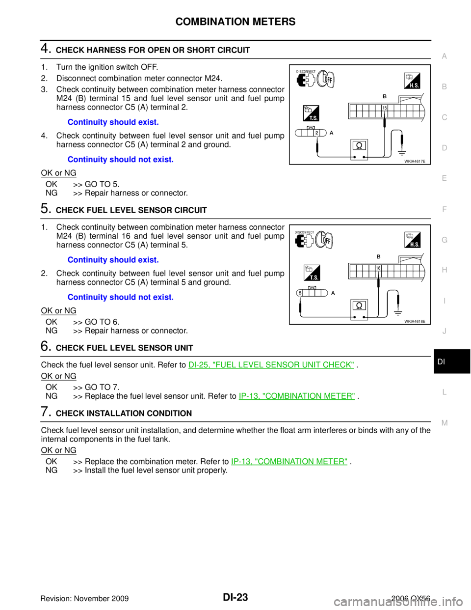
4. CHECK HARNESS FOR OPEN OR SHORT CIRCUIT
1. Turn the ignition switch OFF.
2. Disconnect combination meter connector M24.
3. Check continuity between combination meter harness connector M24 (B) terminal 15 and fuel level sensor unit and fuel pump
harness connector C5 (A) terminal 2.
4. Check continuity between fuel level sensor unit and fuel pump harness connector C5 (A) terminal 2 and ground.
OK or NG
OK >> GO TO 5.
NG >> Repair harness or connector.
5. CHECK FUEL LEVEL SENSOR CIRCUIT
1. Check continuity between combination meter harness connector M24 (B) terminal 16 and fuel level sensor unit and fuel pump
harness connector C5 (A) terminal 5.
2. Check continuity between fuel level sensor unit and fuel pump harness connector C5 (A) terminal 5 and ground.
OK or NG
OK >> GO TO 6.
NG >> Repair harness or connector.
6. CHECK FUEL LEVEL SENSOR UNIT
Check the fuel level sensor unit. Refer to DI-25, "
FUEL LEVEL SENSOR UNIT CHECK" .
OK or NG
OK >> GO TO 7.
NG >> Replace the fuel level sensor unit. Refer to IP-13, "
COMBINATION METER" .
7. CHECK INSTALLATION CONDITION
Check fuel level sensor unit installation, and determine whether the float arm interferes or binds with any of the
internal components in the fuel tank.
OK or NG
OK >> Replace the combination meter. Refer to IP-13, "COMBINATION METER" .
NG >> Install the fuel level sensor unit properly. Continuity should exist.
Continuity should not exist.
WKIA4617E
Continuity should exist.
Continuity should not exist.
WKIA4618E
Page 1145 of 3383

DI-24
COMBINATION METERS
Revision: November 20092006 QX56
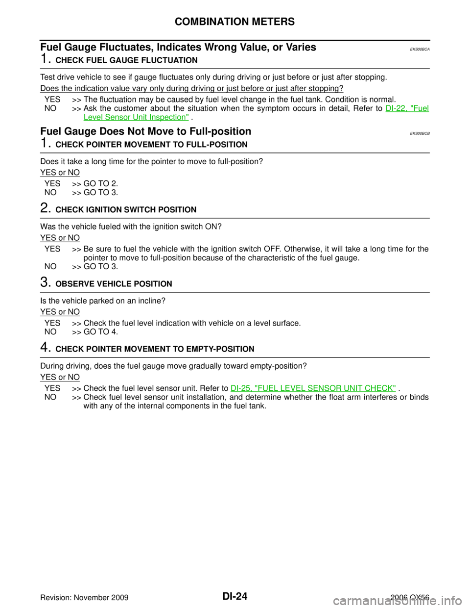
Fuel Gauge Fluctuates, Indicates Wrong Value, or VariesEKS00BCA
1. CHECK FUEL GAUGE FLUCTUATION
Test drive vehicle to see if gauge fluctuates only during driving or just before or just after stopping.
Does the indication value vary only during driving or just before or just after stopping?
YES >> The fluctuation may be caused by fuel level change in the fuel tank. Condition is normal.
NO >> Ask the customer about the situation when the symptom occurs in detail, Refer to DI-22, "
Fuel
Level Sensor Unit Inspection" .
Fuel Gauge Does Not Move to Full-positionEKS00BCB
1. CHECK POINTER MOVEMENT TO FULL-POSITION
Does it take a long time for the pointer to move to full-position?
YES or NO
YES >> GO TO 2.
NO >> GO TO 3.
2. CHECK IGNITION SWITCH POSITION
Was the vehicle fueled with the ignition switch ON?
YES or NO
YES >> Be sure to fuel the vehicle with the ignition switch OFF. Otherwise, it will take a long time for the pointer to move to full-position because of the characteristic of the fuel gauge.
NO >> GO TO 3.
3. OBSERVE VEHICLE POSITION
Is the vehicle parked on an incline?
YES or NO
YES >> Check the fuel level indication with vehicle on a level surface.
NO >> GO TO 4.
4. CHECK POINTER MOVEMENT TO EMPTY-POSITION
During driving, does the fuel gauge move gradually toward empty-position?
YES or NO
YES >> Check the fuel level sensor unit. Refer to DI-25, "FUEL LEVEL SENSOR UNIT CHECK" .
NO >> Check fuel level sensor unit installation, and determine whether the float arm interferes or binds with any of the internal components in the fuel tank.
Page 1146 of 3383
COMBINATION METERSDI-25
C
DE
F
G H
I
J
L
M A
B
DI
Revision: November 2009 2006 QX56
Electrical Components InspectionEKS00BCC
FUEL LEVEL SENSOR UNIT CHECK
For removal, refer to FL-6, "Removal and Installation" .
Check Fuel Level Sensor Unit and Fuel Pump
Check resistance between fuel level sensor unit and fuel pump con-
nector terminals 2 and 5.
*1 and *2: When float rod is in contact with stopper.
Removal and Installation of Combination MeterEKS00BCD
Refer to IP-13, "COMBINATION METER" for removal and installation procedures.
Terminals Float position mm (in) Resistance
value Ω
(Approx.)
25 *1 Empty 25.86 (1.02) 81.66
*2 Full 254.6 (10.02) 6.98
LKIA0402E