Page 3347 of 3383

WW-20
FRONT WIPER AND WASHER SYSTEM
Revision: November 20092006 QX56
3. IPDM E/R INSPECTION
With CONSULT-II
1. Turn ignition switch ON.
2. Select "HI" on "ACTIVE TEST" screen.
3. When front wiper relay and front wiper high relay are operating, check voltage between IPDM E/R termi- nals and ground.
Without CONSULT-II
1. Turn on front wipers using the auto active test. Refer to PG-24, "
Auto Active Test" .
2. When front wiper relay, and front wiper high relay are operating, check voltage between IPDM E/R terminals and ground.
OK or NG
OK >> Replace the front wiper motor. Refer to WW-29, "Wiper Motor and Linkage" .
NG >> Replace IPDM E/R. Refer to PG-30, "
Removal and Installation of IPDM E/R" .
4. COMBINATION SWITCH TO BCM INSPECTION
Select "BCM" on CONSULT-II. With "WIPER" data monitor, check
that "FR WIPER INT", "FR WIPER LOW" and "FR WIPER HI" turn
ON-OFF according to operation of wiper switch.
OK or NG
OK >> GO TO 5.
NG >> Check wiper switch. Refer to WW-6, "
COMBINATION
SWITCH READING FUNCTION" .
5. BCM INSPECTION
Select "BCM" on CONSULT-II. Carry out self-diagnosis of BCM.
Displayed self-diagnosis results
NO DTC>> Replace the BCM. Refer to BCS-20, "BCM" .
CAN COMM CIRCUIT>> Check CAN communication line of BCM.
GO TO BCS-13, "
CAN Communication Inspection Using
CONSULT-II (Self-Diagnosis)" .
Terminals
Voltage
(Approx.)
(+)
(– ) Condition
Connector Terminal
E121 32
Ground Stopped
0
LO operation Battery voltage
35 Stopped
0
HI operation Battery voltage
WKIA2101E
WKIA1018E
SKIA1039E
Page 3350 of 3383

FRONT WIPER AND WASHER SYSTEMWW-23
C
DE
F
G H
I
J
L
M A
B
WW
Revision: November 2009 2006 QX56
2. IPDM E/R TO FRONT WIPERS CIRCUIT INSPECTION
1. Turn ignition switch OFF.
2. Disconnect IPDM E/R connector and front wiper motor connector.
3. Check continuity between IPDM E/R harness connector terminal and front wiper motor harness connector terminal.
OK or NG
OK >> GO TO 3.
NG >> Check for short circuit or open circuit in harness between IPDM E/R and front wiper motor.
3. IPDM E/R INSPECTION
With CONSULT-II
1. Connect IPDM E/R connector and front wiper motor connector.
2. Turn ignition switch ON.
3. Select "LO" on "ACTIVE TEST" screen.
4. When front wiper relay is operating, check voltage between IPDM E/R terminals.
Without CONSULT-II
1. Connect IPDM E/R connector and front wiper motor connector.
2. Turn on front wipers using the auto active test. Refer to PG-24, "
Auto Active Test" .
3. When front wiper relay is operating, check voltage between IPDM E/R terminals.
OK or NG
OK >> Replace the wiper motor. Refer to WW-29, "Wiper Motor
and Linkage" .
NG >> Replace IPDM E/R. Refer to PG-30, "
Removal and Installation of IPDM E/R" .
4. COMBINATION SWITCH TO BCM INSPECTION
Select "BCM" on CONSULT-II. With "WIPER" data monitor, check
that "FR WIPER HI" turns ON-OFF according to operation of wiper
switch.
OK or NG
OK >> Replace BCM. Refer to BCS-20, "BCM" .
NG >> Replace wiper switch. Refer to WW-30, "
Wiper and
Washer Switch" .
Terminals Continuity
Connector Terminal Connector Terminal
E121 32 E233Yes
WKIA2086E
Terminals
Vo l ta g e
(Approx.)
(
– )( +)
Connector Terminal Connector Terminal E122 38
E121 32 Battery
voltage
E124 59
WKIA3198E
WKIA1018E
Page 3352 of 3383

FRONT WIPER AND WASHER SYSTEMWW-25
C
DE
F
G H
I
J
L
M A
B
WW
Revision: November 2009 2006 QX56
3. IPDM E/R INSPECTION
With CONSULT-II
1. Connect IPDM E/R connector and front wiper motor connector.
2. Turn ignition switch ON.
3. Select "HI" on "ACTIVE TEST" screen.
4. When front wiper high relay is operating, check voltage between IPDM E/R terminals.
Without CONSULT-II
1. Connect IPDM E/R connector and front wiper motor connector.
2. Turn on front wipers using the auto active test. Refer to PG-24, "
Auto Active Test" .
3. When front wiper high relay is operating, check voltage between IPDM E/R terminals.
OK or NG
OK >> Replace the wiper motor. Refer to WW-29, "Wiper Motor
and Linkage" .
NG >> Replace IPDM E/R. Refer to PG-30, "
Removal and Installation of IPDM E/R" .
4. COMBINATION SWITCH TO BCM INSPECTION
Select "BCM" on CONSULT-II. With "WIPER" data monitor, check
that "FR WIPER HI" turns ON-OFF according to operation of wiper
switch.
OK or NG
OK >> Replace BCM. Refer to BCS-20, "BCM" .
NG >> Replace wiper switch. Refer to WW-30, "
Wiper and
Washer Switch" .
ONLY FRONT WIPER INTERMITTENT DOES NOT OPERATE
1. COMBINATION SWITCH TO BCM INSPECTION
Select "BCM" on CONSULT-II. With "WIPER" data monitor, check
that "FR WIPER INT" turns ON-OFF according to operation of wiper
switch.
OK or NG
OK >> Replace BCM. Refer to BCS-20, "BCM" .
NG >> Replace wiper switch. Refer to WW-30, "
Wiper and
Washer Switch" .
Te r m i n a l s
Vo l ta g e
(Approx.)
(
– )(+)
Connector Terminal Connector Terminal E122 38
E121 35Battery
voltage
E124 59
WKIA3200E
WKIA1018E
WKIA1018E
Page 3359 of 3383
WW-32
REAR WIPER AND WASHER SYSTEM
Revision: November 20092006 QX56
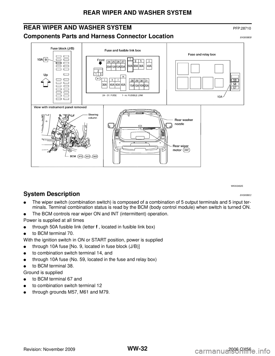
REAR WIPER AND WASHER SYSTEMPFP:28710
Components Parts and Harness Connector LocationEKS00BEB
System DescriptionEKS00BEC
�The wiper switch (combination switch) is composed of a combination of 5 output terminals and 5 input ter-
minals. Terminal combination status is read by the BCM (body control module) when switch is turned ON.
�The BCM controls rear wiper ON and INT (intermittent) operation.
Power is supplied at all times
�through 50A fusible link (letter f , located in fusible link box)
�to BCM terminal 70.
With the ignition switch in ON or START position, power is supplied
�through 10A fuse [No. 9, located in fuse block (J/B)]
�to combination switch terminal 14, and
�through 10A fuse (No. 59, located in the fuse and relay box)
�to BCM terminal 38.
Ground is supplied
�to BCM terminal 67 and
�to combination switch terminal 12
�through grounds M57, M61 and M79.
WKIA3462E