Page 3274 of 3383

TRANSFER ASSEMBLYTF-169
CE F
G H
I
J
K L
M A
B
TF
Revision: November 2009 2006 QX56
d. Install the reverse balls, relief balls and relief springs, accumula-
tor pistons and valve springs to the upper body.
e. Install the lower body and new separator plate to the upper body.
CAUTION:
Do not reuse separator plate.
f. With the lower body down, tighten the two bolts shown.
g. Apply ATF to the new O-rings, and install them to each solenoid valve, switch and terminal body.
CAUTION:
Do not reuse O-rings.
h. Install the following to the control valve assembly:
�Clutch pressure solenoid valve
�2-4WD shift solenoid valve
�Clutch pressure switch
�Line pressure switch
�Transfer fluid temperature sensor
10. Apply ATF to the new lip seals, and install them to the center case.
CAUTION:
�Do not reuse lip seals.
�There are 2 kinds of lip seals (lip seal of large inner diam-
eter: 5 pieces, lip seal of small inner diameter: 2 pieces).
Confirm their position for installation.
SDIA2126E
WDIA0200E
WDIA0198E
SDIA2123E
Page 3275 of 3383
TF-170
TRANSFER ASSEMBLY
Revision: November 20092006 QX56
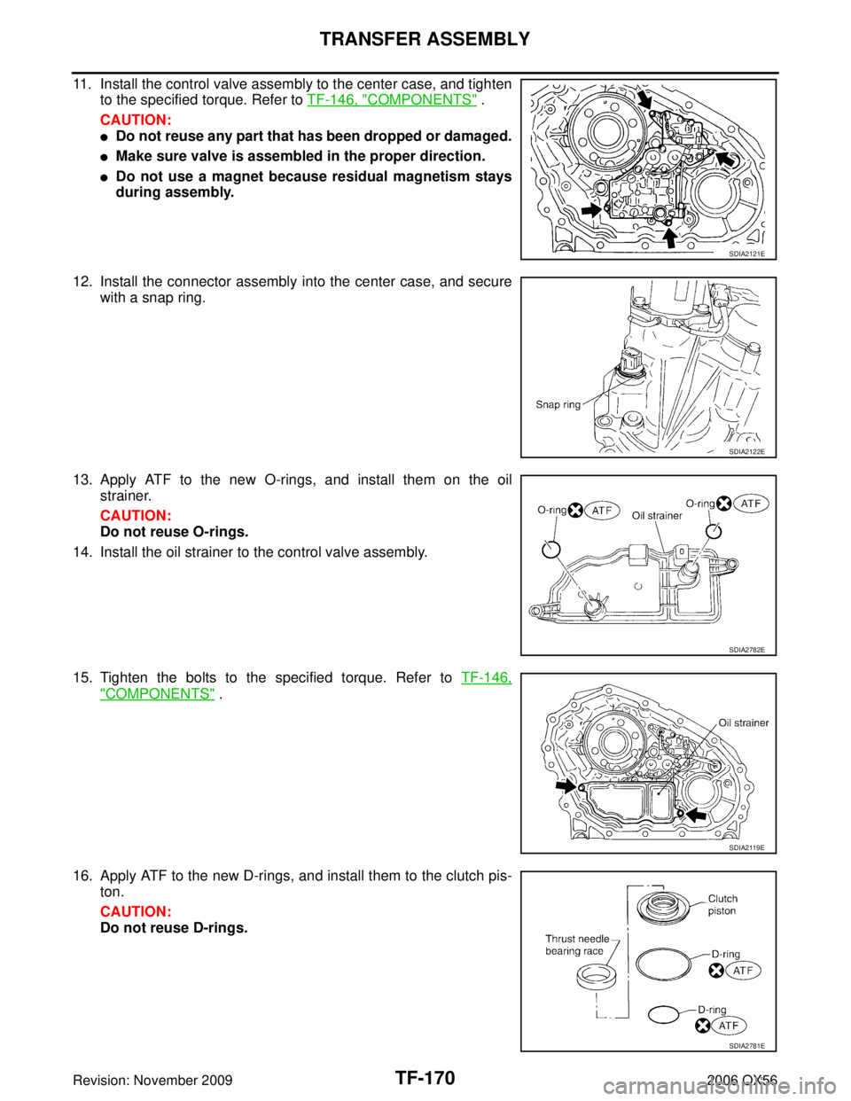
11. Install the control valve assembly to the center case, and tighten
to the specified torque. Refer to TF-146, "
COMPONENTS" .
CAUTION:
�Do not reuse any part that has been dropped or damaged.
�Make sure valve is assembled in the proper direction.
�Do not use a magnet because residual magnetism stays
during assembly.
12. Install the connector assembly into the center case, and secure with a snap ring.
13. Apply ATF to the new O-rings, and install them on the oil strainer.
CAUTION:
Do not reuse O-rings.
14. Install the oil strainer to the control valve assembly.
15. Tighten the bolts to the specified torque. Refer to TF-146,
"COMPONENTS" .
16. Apply ATF to the new D-rings, and install them to the clutch pis- ton.
CAUTION:
Do not reuse D-rings.
SDIA2121E
SDIA2122E
SDIA2782E
SDIA2119E
SDIA2781E
Page 3276 of 3383

TRANSFER ASSEMBLYTF-171
CE F
G H
I
J
K L
M A
B
TF
Revision: November 2009 2006 QX56
17. Install the thrust needle bearing race to the clutch piston.
18. Install the clutch piston to the center case as shown.
CAUTION:
Install so the fitting protrusion of clutch piston aligns with
the dent of center case.
19. Remove all the sealant from the oil pressure check port and inside the center case.
CAUTION:
Remove old sealant adhering to mating surfaces. Also
remove any moisture, oil, or foreign material adhering to
application and mating surfaces.
20. Thread the new oil pressure check plug in 1 or 2 pitches and apply sealant to the oil pressure check plug threads. Tighten to
the specified torque. Refer to TF-146, "
COMPONENTS" .
�Use Genuine Silicone RTV or equivalent. Refer to GI-46,
"RECOMMENDED CHEMICAL PRODUCTS AND SEAL-
ANTS" .
CAUTION:
Do not reuse oil pressure check plug.
21. Install the new snap ring to the clutch hub using suitable tool. CAUTION:
Do not reuse snap ring.
SDIA2189E
SDIA2190E
SDIA3188E
WDIA0101E
Page 3277 of 3383
TF-172
TRANSFER ASSEMBLY
Revision: November 20092006 QX56
22. Apply petroleum jelly to the needle bearing, and install the nee-
dle bearing, spacer, clutch drum and clutch hub to the main-
shaft.
23. Install the new snap ring to the mainshaft. CAUTION:
Do not reuse snap ring.
24. Apply ATF to each plate, then install them into the clutch drum as shown.
25. Install the return spring assembly into the clutch hub.
26. Install the press flange by aligning the notches to the clutch hub as shown.
WDIA0129E
SDIA2192E
SDIA2193E
SMT911C
SDIA2194E
Page 3281 of 3383
TF-176
TRANSFER ASSEMBLY
Revision: November 20092006 QX56
42. Install the front drive shaft rear bearing using Tools.
43. Install the front drive shaft to the front bearing using Tools.
44. Install the drive chain to the front drive shaft and clutch drum.
CAUTION:
Install drive chain by aligning identification marks to the
rear as shown.
45. Tap the front drive shaft while keeping it upright and press-fit the front drive shaft rear bearing.
CAUTION:
Do not tap drive chain.
46. Install the front case assembly. Refer to TF-176, "
Front Case" .
47. Install the rear case assembly. Refer to TF-181, "
Rear Case" .
Front Case
1. Install the carrier bearing to the sun gear using Tools.Tool number A: KV40100621 (J-25273)
B: ST30032000 (J-26010-01)
SDIA2198E
Tool number A: KV40100621 (J-25273)B: ST30032000 (J-26010-01)
SDIA2199E
SDIA2200E
SMT988C
Tool number A: ST30911000 ( — ) B: KV31103300 ( — )
SDIA2179E
Page 3288 of 3383
TF-183
CE F
G H
I
J
K L
M A
B
TF
Revision: November 2009 2006 QX56
SERVICE DATA AND SPECIFICATIONS (SDS)PFP:00030
General SpecificationsEDS003BH
Inspection and Adj")
SERVICE DATA AND SPECIFICATIONS (SDS)TF-183
CE F
G H
I
J
K L
M A
B
TF
Revision: November 2009 2006 QX56
SERVICE DATA AND SPECIFICATIONS (SDS)PFP:00030
General SpecificationsEDS003BH
Inspection and AdjustmentEDS003BI
CLEARANCE BETWEEN INNER GEAR AND OUTER GEAR
Unit: mm (in)
CLUTCH
Unit: mm (in)
PINION GEAR END PLAY
Unit: mm (in)
CLEARANCE BETWEEN SHIFT FORK AND SLEEVE
Unit: mm (in)
SELECTIVE PARTS
Sub-oil Pump
Unit: mm (in)
*: Always check with the Parts Department for the latest parts information. Applied model
VK56DE
Transfer model ATX14B
Fluid capacity (Approx.) (US qt, lmp qt) 3.0 (3-1/8, 2-5/8)
Gear ratio High
1.000
Low 2.596
Number of teeth Sun gear
57
Internal gear 91
Front drive sprocket 38
Front drive shaft 38
ItemSpecification
Main oil pump 0.015 - 0.035 (0.0006 - 0.0014)
Sub-oil pump 0.015 - 0.035 (0.0006 - 0.0014)
ItemLimit value
Drive plate 1.4 (0.055)
ItemStandard
Pinion gear end play 0.1 - 0.7 (0.004 - 0.028)
ItemStandard
Shift fork and sleeve Less than 0.36 (0.0142)
Gear thicknessPart number*
Inner gear Outer gear
9.27 - 9.28 (0.3650 - 0.3654) 31346 0W46231347 0W462
9.28 - 9.29 (0.3654 - 0.3657) 31346 0W46131347 0W461
9.29 - 9.30 (0.3657 - 0.3661) 31346 0W46031347 0W460
Page 3289 of 3383

Revision: November 20092006 QX56
Main Oil Pump
Unit: mm (in)
*: Always check with the Parts Department for the latest parts information.
Control Valve
Unit")
TF-184
SERVICE DATA AND SPECIFICATIONS (SDS)
Revision: November 20092006 QX56
Main Oil Pump
Unit: mm (in)
*: Always check with the Parts Department for the latest parts information.
Control Valve
Unit: mm (in)
*: Always check with the Parts Department for the latest parts information.
Control Valve Spring
Unit: mm (in)
*: Always check with the Parts Department for the latest parts information.
Return Spring
Unit: mm (in)
*: Always check with the Parts Department for the latest parts information. Gear thickness
Part number*
Inner gear Outer gear
8.27 - 8.28 (0.3256 - 0.3260) 31346 7S11231347 7S112
8.28 - 8.29 (0.3260 - 0.3264) 31346 7S11131347 7S111
8.29 - 8.30 (0.3264 - 0.3268) 31346 7S11031347 7S110
Mounting position (Part name) Part number*Outer dia.Overall length
L1 (2-4 shift valve) 31772 21X008.0 (0.315)38.5 (1.516)
L2 (Clutch valve) 31772 80X1110.0 (0.394)40.0 (1.575)
L4 (Pilot valve) 31772 80X1110.0 (0.394)40.0 (1.575)
L5 (Regulator valve) 31741 0W41012.0 (0.472)68.0 (2.677)
Mounting position (Part name) Part number* Free length Outer dia. Overall length
L1 (2-4 shift valve spring) 31742 2W500 31.85 (1.2539) 7.0 (0.276) 0.6 (0.024)
L2 (Clutch valve spring) 31742 2W505 40.6 (1.598) 8.9 (0.350) 0.7 (0.028)
L4 (Pilot valve spring) 31742 0W410 28.1 (1.106) 9.0 (0.354) 1.2 (0.047)
L5 (Regulator valve spring) 31742 2W515 39.7 (1.563) 11.0 (0.433) 1.3 (0.051)
Stamped markPart number*Free length
1 31521 7S11142.7 (1.168)
2 31521 7S11243.1 (1.697)
3 31521 7S11343.6 (1.717)
4 31521 7S11444.0 (1.731)