Page 3252 of 3383
TRANSFER ASSEMBLYTF-147
CE F
G H
I
J
K L
M A
B
TF
Revision: November 2009 2006 QX56
49. 2-4 fork50. Shift fork spring 51. Fork guide
52. Retainer pin 53. Shift rod
1. Dust cover 2. Rear oil seal 3. Rear case
4. Breather tube 5. Seal ring 6. Main oil pump cover
7. Inner gear 8. Outer gear 9. Main oil pump housing
10. D-ring 11. D-ring 12. Clutch piston
13. Thrust needle bearing race 14. Oil strainer 15. O-ring
16. Snap ring 17. Control valve assembly 18. Lip seal (large 5 pieces)
19. Lip seal (small 2 pieces) 20. Gasket 21. Filler plug
22. Oil filter stud 23. O-ring 24. Oil filter
25 ATP switch 26. Neutral-4LO switch 27. Oil pressure check plug
28. Harness bracket 29. Air breather hose clamp 30. Stem bleeder
31. Harness bracket 32. Center case 33. Mainshaft rear bearing
34. C-ring 35. Washer holder 36. Snap ring
37. Sub oil pump housing 38. Outer gear 39. Inner gear
WDIA0302E
Page 3262 of 3383
TRANSFER ASSEMBLYTF-157
CE F
G H
I
J
K L
M A
B
TF
Revision: November 2009 2006 QX56
16. Press the press flange until the snap ring is out of place using
To o l s .
17. Remove the snap ring from the mainshaft using suitable tool.
18. Remove the press flange from the mainshaft.
19. Remove the return spring assembly from the clutch hub.
20. Remove each plate from the clutch drum. Tool number A: ST22452000 (J-34335)
B: ST30911000 ( — )
C: KV31103300 ( — )
S D I A 2 111 E
SDIA2112E
SMT910C
SMT911C
SMT912C
Page 3263 of 3383
TF-158
TRANSFER ASSEMBLY
Revision: November 20092006 QX56
21. Remove the snap ring from the mainshaft.
22. Remove the mainshaft from the clutch drum and clutch hub
using suitable tool.
23. Remove the needle bearing and spacer from the mainshaft.
24. Remove the snap ring from the clutch hub using suitable tool.
25. Remove the oil pressure check plug from the oil pressure check port.
26. Apply air gradually from the oil pressure check port, and remove the clutch piston assembly from the center case.
SDIA2113E
SMT914C
WDIA0101E
SDIA3188E
SDIA2116E
Page 3264 of 3383
TRANSFER ASSEMBLYTF-159
CE F
G H
I
J
K L
M A
B
TF
Revision: November 2009 2006 QX56
27. Remove the thrust needle bearing race from the clutch piston by
hooking a edge into 3 notches of the thrust needle bearing race
using suitable tool.
CAUTION:
Do not damage clutch piston or thrust needle bearing race.
28. Remove the two D-rings from the clutch piston.
29. Remove the mainshaft rear bearing from the center case using To o l .
30. Remove the two bolts and oil strainer.
31. Remove the two O-rings from the oil strainer.
SDIA2118E
SDIA2781E
Tool number : KV38100300 (J-25523)
SDIA2129E
SDIA2119E
SDIA2782E
Page 3266 of 3383
TRANSFER ASSEMBLYTF-161
CE F
G H
I
J
K L
M A
B
TF
Revision: November 2009 2006 QX56
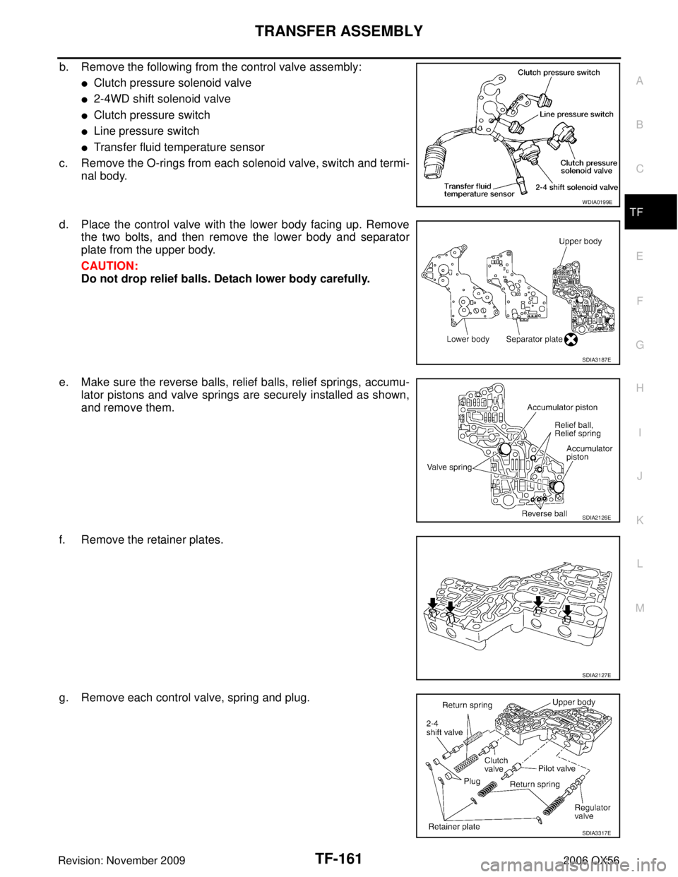
b. Remove the following from the control valve assembly:
�Clutch pressure solenoid valve
�2-4WD shift solenoid valve
�Clutch pressure switch
�Line pressure switch
�Transfer fluid temperature sensor
c. Remove the O-rings from each solenoid valve, switch and termi- nal body.
d. Place the control valve with the lower body facing up. Remove the two bolts, and then remove the lower body and separator
plate from the upper body.
CAUTION:
Do not drop relief balls. Detach lower body carefully.
e. Make sure the reverse balls, relief balls, relief springs, accumu- lator pistons and valve springs are securely installed as shown,
and remove them.
f. Remove the retainer plates.
g. Remove each control valve, spring and plug.
WDIA0199E
SDIA3187E
SDIA2126E
SDIA2127E
SDIA3317E
Page 3269 of 3383

TF-164
TRANSFER ASSEMBLY
Revision: November 20092006 QX56
Planetary Carrier
�Measure the end play of each pinion gear. If it is out of specifica-
tion, replace the planetary carrier assembly with a new one.
�Check the working face of each gear and bearing for damage,
burrs, partial wear, dents and other abnormality. If any is found,
replace the planetary carrier assembly with a new one.
Sun Gear
�Check if the oil passage of the sun gear assembly is clogged.
For this, try to pass a 3.6 mm (0.142 in) dia. pin through the oil
passage as shown.
�Check the sliding and contact surface of each gear and bearing
for damage, burrs, partial wear, dents, and other abnormality. If
any is found, replace the sun gear assembly with a new one.
Internal Gear
�Check the internal gear teeth for damage, partial wear, dents
and other abnormality. If any is found, replace the internal gear
with a new one.
Gears and Drive Chain
�Check the gear faces and shaft for wear, cracks, damage, and
seizure.
�Check the surfaces which contact the sun gear, clutch drum,
clutch hub, press flange, clutch piston and each bearing for
damage, peel, partial wear, dents, bending, or other abnormal
damage. If any is found, replace with a new one.Pinion gear end play : 0.1 - 0.7 mm (0.004 - 0.028 in)
PDIA0185E
PDIA0186E
SMT008D
SMT944C
Page 3270 of 3383

TRANSFER ASSEMBLYTF-165
CE F
G H
I
J
K L
M A
B
TF
Revision: November 2009 2006 QX56
Bearing
�Make sure the bearings roll freely and are free from noise, pit-
ting and cracks.
Main Oil Pump
1. Check the inner and outer circumference, tooth face, and side-
face of the inner and outer gears for damage or abnormal wear.
2. Measure the side clearance between the main oil pump housing edge and the inner and outer gears.
3. Make sure the side clearance is within specification. If the mea- surement is out of specification, replace the inner and outer
gears with new ones as a set. Refer to TF-165, "
Main Oil Pump"
.
Sub-oil Pump
1. Check the inner and outer circumference, tooth face, and side-
face of the inner and outer gears for damage or abnormal wear.
2. Measure the side clearance between the sub oil pump housing edge and the inner and outer gears.
3. Make sure the side clearance is within specification. If the mea- surement is out of specification, replace the inner and outer
gears with new ones as a set. Refer to TF-165, "
Sub-oil Pump" .
Control Valve
�Check resistance between the terminals of the clutch pressure
solenoid valve, 2-4WD shift solenoid valve, clutch pressure
switch, line pressure switch and the transfer fluid temperature
sensor. Refer to TF-90, "
COMPONENT INSPECTION" (clutch
pressure solenoid valve), TF-94, "
COMPONENT INSPECTION"
(2-4WD solenoid valve), TF-107, "COMPONENT INSPECTION"
(clutch pressure switch), TF-110, "COMPONENT INSPECTION"
(line pressure switch) and TF-104, "COMPONENT INSPEC-
TION" (transfer fluid temperature sensor).
SDIA2175E
Specification : 0.015 - 0.035 mm (0.0006 - 0.0014 in)
SDIA2174E
Specification : 0.015 - 0.035 mm (0.0006 - 0.0014 in)
SDIA2173E
WDIA0199E
Page 3271 of 3383

TF-166
TRANSFER ASSEMBLY
Revision: November 20092006 QX56
�Check the sliding faces of the control valves and plugs for
abnormality. If any is found, replace the control valve assembly
with a new one. Refer to TF-165, "
Control Valve" .
CAUTION:
Replace control valve body together with clutch return
spring as a set.
�Check each control valve spring for damage or distortion. Also
check its free length, outer diameter and wire diameter. If any
damage or fatigue is found, replace the control valve body with a
new one. Refer to TF-166, "
Return Spring" .
CAUTION:
Replace control valve body together with clutch return
spring as a set.
Clutch
�Check the drive plate facings and driven plate for damage,
cracks or other abnormality. If any abnormalities are found,
replace with a new one.
�Check the thickness of the drive plate facings and driven plate.
Refer to TF-183, "
CLUTCH" .
CAUTION:
�Measure facing thickness at 3 points to take an average.
�Check all drive and driven plates.
�Check return spring for damage or deformation.
�Do not remove spring from plate.
Return Spring
�Check the stamped mark shown. Then, check that the free
lengths, (include thickness of plate) are within specifications. If
any abnormality is found, replace with a new return spring
assembly of the same stamped number. Refer to TF-166,
"Return Spring" .
SMT947C
SMT948C
SMT949C
SDIA2176E