Page 2563 of 3383

LT-156
INTERIOR ROOM LAMP
Revision: November 20092006 QX56
4. CHECK IGNITION KEYHOLE ILLUMINATION BULB
1. Turn ignition switch OFF.
2. Disconnect ignition keyhole illumination connector.
3. Check continuity between ignition keyhole illumination terminals + and –.
OK or NG
OK >> GO TO 5.
NG >> Replace ignition keyhole illumination.
5. CHECK IGNITION KEYHOLE ILLUMINATION CIRCUIT
1. Disconnect BCM connector.
2. Check continuity between BCM harness connector M18 terminal 1 and ignition keyhole illumination harness connector M150 ter-
minal –.
OK or NG
OK >> Replace BCM if ignition keyhole illumination does not work after setting the connector again. Refer to BCS-20,
"BCM" .
NG >> Repair harness or connector.
6. CHECK IGNITION KEYHOLE ILLUMINATION CIRCUIT
1. Turn ignition switch OFF.
2. Disconnect BCM connector and keyhole illumination connector.
3. Check continuity between BCM harness connector M20 terminal 56 and ignition keyhole illumination harness connector M150
terminal +.
OK or NG
OK >> Replace BCM if ignition keyhole illumination does not work after setting the connector again. Refer to BCS-20,
"BCM" .
NG >> Repair harness or connector. + - –
: Continuity should exist.
WKIA3556E
– - 1 : Continuity should exist.
WKIA1911E
+ - 56: Continuity should exist.
WKIA1912E
Page 2582 of 3383

BULB SPECIFICATIONSLT-175
C
DE
F
G H
I
J
L
M A
B
LT
Revision: November 2009 2006 QX56
BULB SPECIFICATIONSPFP:26297
HeadlampEKS00D83
*: Always check with the Parts Department for the latest parts information.
Exterior LampEKS00D84
*: Always check with the Parts Department for the latest parts information.
Interior Lamp/IlluminationEKS00D85
*: Always check with the Parts Department for the latest parts information.Item
Wattage (W)*
Low 35 (D2R)
High 60 (HB3)
ItemWattage (W)*
Front combination lamp Parking lamp (inner)
7
Parking lamp (outer) 7
Side marker lamp (front) 7
Rear combination lamp Stop/Tail lamp
*
Side marker lamp (rear) *
Turn signal lamp 27
Back-up lamp *
Turn/fog lamp Fog
55 (H3)
Turn 21
License plate lamp 5
High-mounted stop lamp *
ItemWattage (W)*
Glove box lamp 3.4
Room/Map lamp 8
Console box illumination lamp *
A/T device lamp 2
Foot lamp 3.4
Step lamp 3.8
Cargo lamp 7
Va n i t y l a m p 1.32
Personal lamp 5
Puddle lamp 8
Ignition keyhole illumination lamp 0.74
Page 2596 of 3383
OIL PUMPLU-13
C
DE
F
G H
I
J
K L
M A
LU
Revision: November 2009 2006 QX56
OIL PUMPPFP:15010
Removal and InstallationEBS00LMW
REMOVAL
1. Remove front cover. Refer to EM-38, "REMOVAL" .
2. Remove the oil pump drive spacer.
3. Remove the oil pump.
INSTALLATION
Installation is in the reverse order of removal, paying attention of the following:
�When inserting the oil pump drive spacer, align the crankshaft
key and the flat face of the inner rotor.
�If they are not aligned, rotate the oil pump inner rotor by hand.
�Make sure that the each part is aligned and tap lightly until it
reaches the end.
WBIA0415E
1. Oil pump body 2. Outer rotor3. Inner rotor
4. Oil pump cover 5. Oil pump drive spacer6. Regulator valve
7. Regulator spring 8. Regulator plug
KBIA2512E
KBIA2490E
Page 2658 of 3383

POWER SUPPLY ROUTING CIRCUITPG-17
C
DE
F
G H
I
J
L
M A
B
PG
Revision: November 2009 2006 QX56
Fuse EKS00GKH
�If fuse is blown, be sure to eliminate cause of incident before
installing new fuse.
�Use fuse of specified rating. Never use fuse of more than speci-
fied rating.
�Do not partially install fuse; always insert it into fuse holder prop-
erly.
�Remove fuse for “ELECTRICAL PARTS (BAT)” if vehicle is not
used for a long period of time.
Fusible Link EKS00GKI
A melted fusible link can be detected either by visual inspection or by feeling with finger tip. If its condition is
questionable, use circuit tester or test lamp.
CAUTION:
�If fusible link should melt, it is possible that critical circuit (power supply or large current carrying
circuit) is shorted. In such a case, carefully check and eliminate cause of incident.
�Never wrap outside of fusible link with vinyl tape.
�Never let fusible link touch any other wiring harness, vinyl or rubber parts.
Circuit Breaker (Built Into BCM)EKS00GKJ
For example, when current is 30A, the circuit is broken within 8 to 20
seconds.
A circuit breaker is used for the following systems:
�Power windows
�Power door locks
�Remote keyless entry system
�Power sunroof
�Rear window wiper
CEL083
SBF284E
Page 2704 of 3383

HARNESSPG-63
C
DE
F
G H
I
J
L
M A
B
PG
Revision: November 2009 2006 QX56
HORNWW Horn
HSEAT SE Heated Seat
ICC ACS Intelligent Cruise Control
ICCBOF EC ICC Brake Switch
ICC/BS EC ICC Steering Switch
ICC/SW EC ICC Brake Switch
I/MIRR GW Inside Mirror (Auto Anti-Dazzling Mirror)
IATS EC Intake Air Temperature Sensor
IGNSYS EC Ignition System
ILL LT Illumination
INJECT EC Injector
INT/L LT Room/Map, Vanity, Cargo, Personal, Foot, Step, and Puddle Lamps
KEYLES BL Remote Keyless Entry System
KS EC Knock Sensor
MAFS EC Mass Air Flow Sensor
MAIN EC Main Power Supply and Ground Circuit
METER DI Speedometer, Tachometer, Temp. and Fuel Gauges
MIL/DL EC Malfunction Indicator Lamp
MIRROR GW Door Mirror
NATS BL Nissan Anti-Theft System
NAVI AV Navigation System
O2H2B1 EC Rear Heated Oxygen Sensor 2 Heater Bank 1
O2H2B2 EC Rear Heated Oxygen Sensor 2 Heater Bank 2
O2S2B1 EC Heated Oxygen Sensor 2 Bank 1
O2S2B2 EC Heated Oxygen Sensor 2 Bank 2
P/SCKT WW Power Socket
PGC/V EC EVAP Canister Purge Volume Control Solenoid Valve
PHASE EC Camshaft Position Sensor (PHASE) (Bank 1)
PNP/SW EC Park/Neutral Position Switch
POS EC Crankshaft Position Sensor (POS)
POWER PG Power Supply Routing
PRE/SE EC EVAP Control System Pressure Sensor
PS/SEN EC Power Steering Pressure Sensor
R/VIEW DI Rear View Monitor
RP/SEN EC Refrigerant Pressure Sensor
SEN/PW EC Sensor Power Supply
SHIFT AT A/T Shift Lock System
SONAR DI Rear Sonar System
SROOF RF Sunroof
SRS SRS Supplemental Restraint System
START SC Starting System
STOP/L LT Stop Lamp
T/TOW LT Trailer Tow
T/WARN WT Low Tire Pressure Warning System
TAIL/L LT Parking, License and Tail Lamps
T/F TFTransfer Case
TPS1 EC Throttle Position Sensor
TPS2 EC Throttle Position Sensor
TPS3 EC Throttle Position Sensor
TRNSCV BL HOMELINK® Universal Transceiver
TURN LT Turn Signal and Hazard Warning Lamps
VDC BRC Vehicle Dynamic Control System
Page 2743 of 3383
PS-10
STEERING COLUMN
Revision: November 20092006 QX56
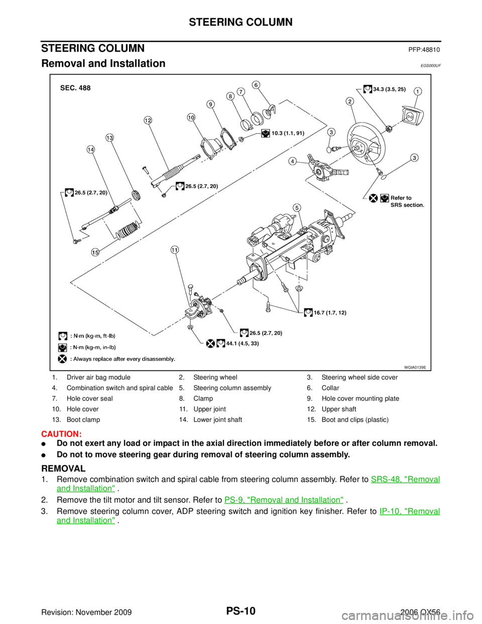
STEERING COLUMNPFP:48810
Removal and InstallationEGS000UF
CAUTION:
�Do not exert any load or impact in the axial direction immediately before or after column removal.
�Do not to move steering gear during removal of steering column assembly.
REMOVAL
1. Remove combination switch and spiral cable from steering column assembly. Refer to SRS-48, "Removal
and Installation" .
2. Remove the tilt motor and tilt sensor. Refer to PS-9, "
Removal and Installation" .
3. Remove steering column cover, ADP steering switch and ignition key finisher. Refer to IP-10, "
Removal
and Installation" .
1. Driver air bag module2. Steering wheel 3. Steering wheel side cover
4. Combination switch and spiral cable 5. Steering column assembly 6. Collar
7. Hole cover seal 8. Clamp 9. Hole cover mounting plate
10. Hole cover 11. Upper joint 12. Upper shaft
13. Boot clamp 14. Lower joint shaft 15. Boot and clips (plastic)
WGIA0139E
Page 2912 of 3383

BATTERYSC-7
C
DE
F
G H
I
J
L
M A
B
SC
Revision: November 2009 2006 QX56
1. Turn off all loads on the vehicle electrical system. Clean or repair
as necessary.
2. Visually inspect the battery, battery terminals and cable ends with ignition switch in “OFF” position.
NOTE:
The contact surface between the battery terminals, cable ends
and tester leads must be clean for a valid test. A poor connec-
tion will prevent testing and a “CHECK CONNECTION” mes-
sage will appear during the test procedures. If this occurs, clean
the battery post and terminals, reconnect them and restart the
test.
3. Connect the red tester lead clamp to the positive battery termi- nal, and the black to the negative terminal.
4. The tester will turn on automatically. Using the arrow keys, select “IN-VEHICLE” on the tester and then press the “ENTER ”
key.
5. Locate the battery type and rating stamped or written on the top case of the battery to be tested.
NOTE:
The battery rating will be either of the following:
�CCA: Cold Cranking Amps (490 CCA, 550 CCA, etc.)
�JIS: Japanese Industrial Standard.
When using the Battery Tester use the CCA rating only.
�The tester requires the CCA rating for the battery be entered
exactly as it is written or stamped on the battery.
�(U.S. market) Refer to the latest "Battery Testing" Technical
Service Bulletin (TSB) for a chart which contains these ratings
listed by vehicle.
�You must not use the JIS rating.
6. Using the arrow and “ENTER” keys alternately, select the battery type and rating.
NOTE:
The tester lists five choices; CCA, JIS, IEC, DIN, and EN. Only use CCA.
7. Press “ENTER” to begin the test. Diagnosis results are dis-
played on the tester. Refer to SC-8, "
DIAGNOSTIC RESULT
ITEM CHART" .
SEL404X
SEL405X
WKIA4228E
SEL407X
Page 2942 of 3383
AUTOMATIC DRIVE POSITIONERSE-11
C
DE
F
G H
J
K L
M A
B
SE
Revision: November 2009 2006 QX56
AUTOMATIC DRIVE POSITIONERPFP:28491
Component Parts And Harness Connector LocationEIS0058U
1. Fuse block (J/B)2. Fuse and relay box3. Fuse and fusible link box
4. A. Automatic drive positioner control unit M33, M34
B. Pedal adjusting motor E109,
E110 5. A. Steering column
B. Key switch and key lock solenoid
M27
C. BCM M18, M19, M20 (View with
instrument panel removed) 6. A. Door mirror remote control switch
D10
B. Seat memory switch D5
LIIA2361E