Page 2669 of 3383

Revision: November 20092006 QX56
IPDM E/R Power/Ground Circuit InspectionEKS00BN9
1. FUSE AND FUSIBLE LINK INSPECTION
Check that the")
PG-28
IPDM E/R (INTELLIGENT POWER DISTRIBUTION MODULE ENGINE ROOM)
Revision: November 20092006 QX56
IPDM E/R Power/Ground Circuit InspectionEKS00BN9
1. FUSE AND FUSIBLE LINK INSPECTION
Check that the following fusible links or IPDM E/R fuses are not blown.
OK or NG
OK >> GO TO 2.
NG >> Replace fuse or fusible link.
2. POWER CIRCUIT INSPECTION
1. Disconnect IPDM E/R harness connector E118.
2. Check voltage between IPDM E/R harness connector E118 terminals 1, 2 and ground.
OK or NG
OK >> GO TO 3.
NG >> Repair or replace IPDM E/R power circuit harness.
3. GROUND CIRCUIT INSPECTION
1. Disconnect IPDM E/R harness connectors E122 and E124.
2. Check continuity between IPDM E/R harness connector E122 terminal 38, and E124 terminal 59 and ground.
OK or NG
OK >> Inspection End.
NG >> Repair or replace IPDM E/R ground circuit harness.
Terminal No. Signal nameFuse, fusible link No.
1, 2 Battery power a, c, d
Battery voltage should exist.
SKIA1987E
Continuity should exist.
WKIA1453E
Page 2717 of 3383
PG-76
FUSE BLOCK-JUNCTION BOX (J/B)
Revision: November 20092006 QX56
FUSE BLOCK-JUNCTION BOX (J/B)PFP:24350
Terminal ArrangementEKS00BNN
WKIA4690E
Page 2718 of 3383
FUSE AND FUSIBLE LINK BOXPG-77
C
DE
F
G H
I
J
L
M A
B
PG
Revision: November 2009 2006 QX56
FUSE AND FUSIBLE LINK BOXPFP:24381
Terminal ArrangementEKS00BNO
WKIA4691E
Page 2719 of 3383
PG-78
FUSE AND RELAY BOX
Revision: November 20092006 QX56
FUSE AND RELAY BOXPFP:24012
Terminal ArrangementEKS00BNP
WKIA4692E
Page 2785 of 3383
RF-10
SUNROOF
Revision: November 20092006 QX56
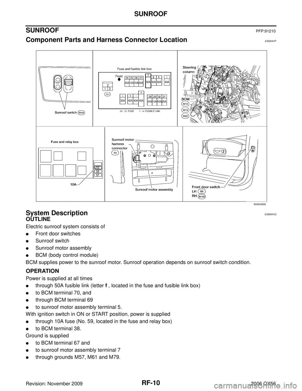
SUNROOFPFP:91210
Component Parts and Harness Connector LocationEIS004VP
System DescriptionEIS004VQ
OUTLINE
Electric sunroof system consists of
�Front door switches
�Sunroof switch
�Sunroof motor assembly
�BCM (body control module)
BCM supplies power to the sunroof motor. Sunroof operation depends on sunroof switch condition.
OPERATION
Power is supplied at all times
�through 50A fusible link (letter f , located in the fuse and fusible link box)
�to BCM terminal 70, and
�through BCM terminal 69
�to sunroof motor assembly terminal 5.
With ignition switch in ON or START position, power is supplied
�through 10A fuse (No. 59, located in the fuse and relay box)
�to BCM terminal 38.
Ground is supplied
�to BCM terminal 67 and
�to sunroof motor assembly terminal 7
�through grounds M57, M61 and M79.
WIIA0465E
Page 2793 of 3383

RF-18
SUNROOF
Revision: November 20092006 QX56
BCM Power Supply and Ground Circuit CheckEIS004W1
1. CHECK FUSE
Check the following BCM fuse and fusible link.
NOTE:
Refer to RF-10, "
Component Parts and Harness Connector Location" .
OK or NG
OK >> GO TO 2.
NG >> If fuse is blown, be sure to eliminate cause of problem before installing new fuse. Refer to PG-4,
"POWER SUPPLY ROUTING CIRCUIT" .
2. CHECK POWER SUPPLY CIRCUIT
1. Turn ignition switch OFF.
2. Disconnect BCM connectors.
3. Check voltage between BCM connectors M18 and M20 termi- nals 38, 70 and ground.
OK or NG
OK >> GO TO 3.
NG >> Repair or replace harness.
3. CHECK GROUND CIRCUIT
Check continuity between BCM connector M20 terminal 67 and
ground.
OK or NG
OK >> Power supply and ground circuit is OK.
NG >> Repair or replace harness.
Retained power operation does not operate properly. 1. Check the retained power operation mode setting
RF-112. BCM power supply and ground circuit checkRF-18
3. Door switch checkRF-21
4. Replace sunroof motor assemblyRF-27
Motor does not stop at the sunroof fully-open or fully-
closed position.1. Initialization procedure check
RF-11
2. Replace sunroof motor assemblyRF-27
Sunroof does not do the interruption detection.1. Replace sunroof motor assembly RF-27
SymptomDiagnostic procedure and repair order Refer to page
Component PartsTerminal No. (SIGNAL) AmpereNo. Location
BCM 38 (IGN power supply)
10A59 Fuse and relay box
70 (BAT power supply) 50Af Fuse and fusible link box
ConnectorTe r m i n a l s
ConditionVoltage
(Approx.)
(+) (– )
M18 38
Ground Ignition switch ON
Battery voltage
M20 70 Igniting switch OFF
WIIA0229E
Connector TerminalsContinuity
M20 67Ground YES
LIIA0915E
Page 2863 of 3383

RSU-24
TROUBLE DIAGNOSES FOR SYMPTOMS
Revision: November 20092006 QX56
TROUBLE DIAGNOSES FOR SYMPTOMSPFP:99999
Load Leveling Rear Air Suspension System Does Not OperateEES001HD
1. CHECK WARNING LAMP ACTIVATION
Make sure warning lamp remains off while driving.
OK or NG
OK >> GO TO 2.
NG >> Carry out self-diagnosis. Refer to RSU-14, "
SELF-DIAGNOSIS" .
2. CHECK FUSES AND FUSIBLE LINK
Check that the following fuses and fusible link are not blown.
OK or NG
OK >> GO TO 3.
NG >> If fuse or fusible link is blown, be sure to eliminate cause of malfunction before installing new fuse or fusible link. Refer to PG-4, "
POWER SUPPLY ROUTING CIRCUIT" .
3. CHECK SUSPENSION CONTROL UNIT POWER AND GROUND
1. Turn the ignition switch ON.
2. Check voltage between suspension control unit connector B3 terminal 6 and ground and between suspension control unit con-
nector B3 terminal 7 and ground.
3. Turn the ignition switch OFF.
4. Check continuity between suspension control unit connector B3 terminal 16 and ground.
OK or NG
OK >> GO TO 4.
NG >> Repair harness or connector.
Unit Terminals Signal nameFuse and fusible link No.
Suspension control unit 6
Ignition switch ON or START 12 (10A)
7 Battery power 29 (10A)
Compressor motor relay 5 g (30A)
Combination meter 24
Ignition switch ON or START 14 (10A)
8 Battery power 19 (10A)
Voltage: Approx. 12V
WEIA0069E
16 - Ground Continuity should exist.
WEIA0070E
Page 2915 of 3383

SC-10
STARTING SYSTEM
Revision: November 20092006 QX56
STARTING SYSTEMPFP:23300
System DescriptionEKS00B7B
Power is supplied at all times:
�through 40A fusible link (letter m , located in the fuse and fusible link box)
�to ignition switch terminal B.
With the ignition switch in the START position, power is supplied:
�from ignition switch terminal ST
�to IPDM E/R terminal 21.
With the ignition switch in the ON or START position, power is supplied to IPDM E/R (intelligent power distribu-
tion module engine room) CPU.
With the selector lever in the P or N position, power is supplied:
�through A/T assembly terminal 9
�to IPDM E/R terminal 48.
Ground is supplied at all times:
�to IPDM E/R terminals 38 and 59
�through body grounds E9, E15 and E24.
Then the starter relay is turned on.
The IPDM E/R is energized and power is supplied:
�from terminal 19 of the IPDM E/R
�to terminal 1 of the starter motor windings.
The starter motor plunger closes and provides a closed circuit between the battery and the starter motor. The
starter motor is grounded to the cylinder block. With power and ground supplied, the starter motor operates.

Revision: November 20092006 QX56
FUSE BLOCK-JUNCTION BOX (J/B)PFP:24350
Terminal ArrangementEKS00BNN
WKIA4690E")