Page 2261 of 3383
IP-12
INSTRUMENT PANEL ASSEMBLY
Revision: November 20092006 QX56
CLUSTER LID C
CAUTION:
When removing and installing, place shop cloths onto surrounding parts to protect A/T finisher and
center console from damage.
Removal
1. Disconnect battery negative terminal.
2. Remove A/T finisher. Refer to IP-13, "
A/T FINISHER" .
3. Remove center console. Refer to IP-10, "
INSTRUMENT PANEL ASSEMBLY" .
4. Pull to disconnect cluster lid C clips.
5. Disconnect cluster lid C electrical connectors.
Installation
Installation is in the reverse order of removal.
CLUSTER LID D
CAUTION:
When removing and installing, place shop cloths onto surrounding parts to protect A/T finisher and
center console from damage.
Removal
1. Remove cluster lid C. Refer to IP-12, "Removal" .
2. Remove instrument lower cover LH. Refer to IP-13, "
INSTRUMENT LOWER COVER LH" .
3. Remove glove box. Refer to IP-15, "
Glove Box" .
WIIA0915E
LIIA1337E
Page 2263 of 3383
IP-14
INSTRUMENT PANEL ASSEMBLY
Revision: November 20092006 QX56
Lower Instrument Panel RH and Glove BoxEIS007X9
REMOVAL AND INSTALLATION
Removal
1. Remove the instrument lower cover RH.
1. Clip2. Damper clip 3. Glove box damper
4. Glove box housing 5. Rubber stopper 6. Glove box pin
7. Glove box door 8. Glove box striker 9. Fuse block cover
10. Glove box assembly
LIIA1251E
LLIA0072E
Page 2264 of 3383
INSTRUMENT PANEL ASSEMBLYIP-15
C
DE
F
G H
J
K L
M A
B
IP
Revision: November 2009 2006 QX56
2. Remove glove box assembly screws, using power tool.
3. Disconnect glove box lamp.
Installation
Installation is in the reverse order of removal.
Glove BoxEIS007XA
DISASSEMBLY AND ASSEMBLY
Disassembly
1. Remove damper clip from glove box.
2. Remove glove box pins and glove box.
3. Remove glove box striker screws, using power tool and remove glove box striker.
4. Remove fuse block cover.
5. Remove glove box damper screws and remove glove box damper.
Assembly
Assembly is in the reverse order of disassembly.
Page 2266 of 3383

INSTRUMENT PANEL ASSEMBLYIP-17
C
DE
F
G H
J
K L
M A
B
IP
Revision: November 2009 2006 QX56
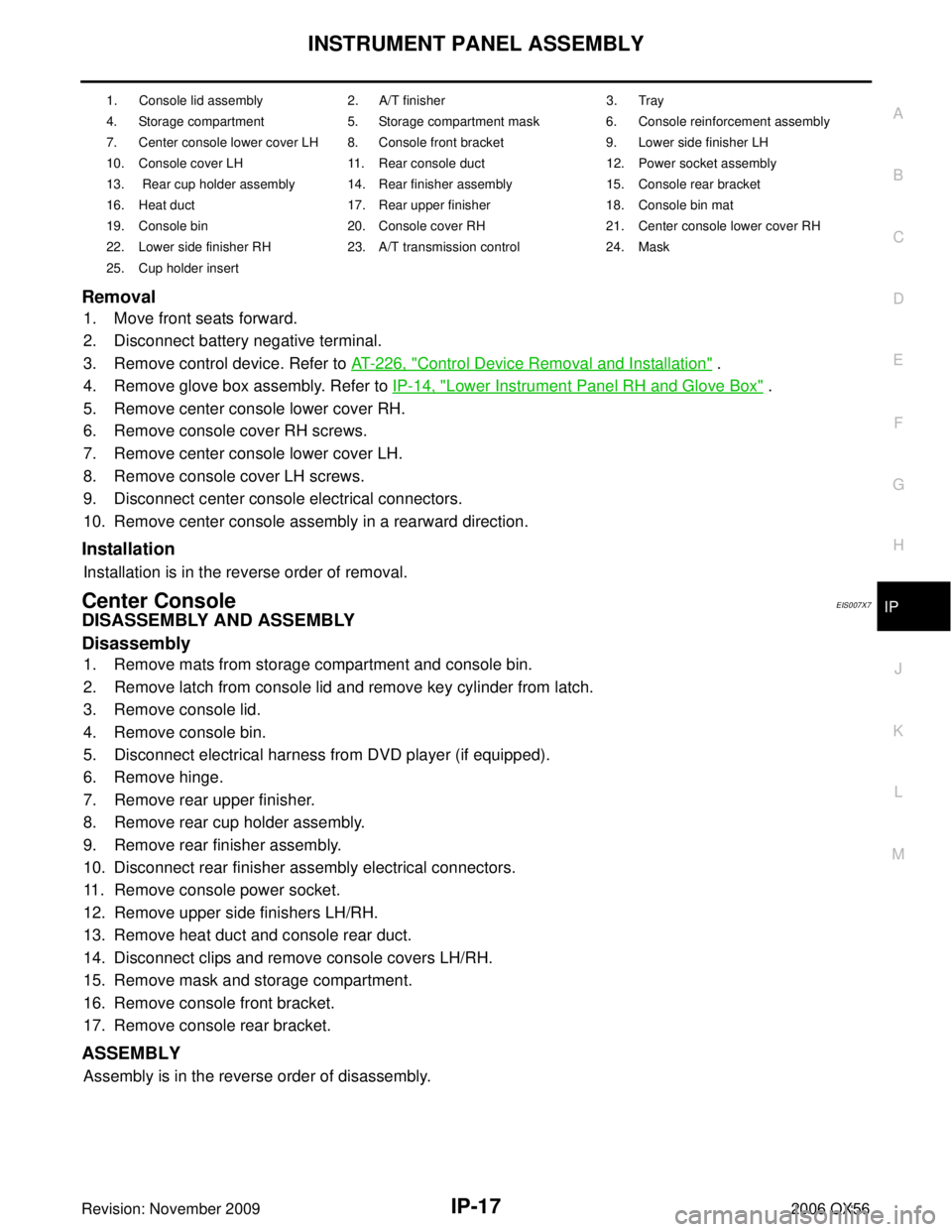
Removal
1. Move front seats forward.
2. Disconnect battery negative terminal.
3. Remove control device. Refer to AT- 2 2 6 , "
Control Device Removal and Installation" .
4. Remove glove box assembly. Refer to IP-14, "
Lower Instrument Panel RH and Glove Box" .
5. Remove center console lower cover RH.
6. Remove console cover RH screws.
7. Remove center console lower cover LH.
8. Remove console cover LH screws.
9. Disconnect center console electrical connectors.
10. Remove center console assembly in a rearward direction.
Installation
Installation is in the reverse order of removal.
Center ConsoleEIS007X7
DISASSEMBLY AND ASSEMBLY
Disassembly
1. Remove mats from storage compartment and console bin.
2. Remove latch from console lid and remove key cylinder from latch.
3. Remove console lid.
4. Remove console bin.
5. Disconnect electrical harness from DVD player (if equipped).
6. Remove hinge.
7. Remove rear upper finisher.
8. Remove rear cup holder assembly.
9. Remove rear finisher assembly.
10. Disconnect rear finisher assembly electrical connectors.
11. Remove console power socket.
12. Remove upper side finishers LH/RH.
13. Remove heat duct and console rear duct.
14. Disconnect clips and remove console covers LH/RH.
15. Remove mask and storage compartment.
16. Remove console front bracket.
17. Remove console rear bracket.
ASSEMBLY
Assembly is in the reverse order of disassembly.
1. Console lid assembly 2. A/T finisher 3. Tray
4. Storage compartment 5. Storage compartment mask 6. Console reinforcement assembly
7. Center console lower cover LH 8. Console front bracket 9. Lower side finisher LH
10. Console cover LH 11. Rear console duct 12. Power socket assembly
13. Rear cup holder assembly 14. Rear finisher assembly 15. Console rear bracket
16. Heat duct 17. Rear upper finisher 18. Console bin mat
19. Console bin 20. Console cover RH 21. Center console lower cover RH
22. Lower side finisher RH 23. A/T transmission control 24. Mask
25. Cup holder insert
Page 2565 of 3383

LT-158
ILLUMINATION
Revision: November 20092006 QX56
�to combination meter terminal 8
With the ignition switch in the ON or START position, power is supplied
�to ignition relay, located in the IPDM E/R, and
�through 10A fuse (No. 59, located in the fuse and relay box)
�to BCM terminal 38, and
�through 10A fuse [No. 14, located in the fuse block (J/B)]
�to combination meter terminal 24.
Ground is supplied
�to BCM terminal 67 and
�to combination meter terminal 17
�through grounds M57, M61 and M79, and
�to IPDM E/R terminals 38 and 59
�through grounds E9, E15 and E24.
ILLUMINATION OPERATION BY LIGHTING SWITCH
With the lighting switch in the 1ST or 2ND position (or if the auto light system is activated), the BCM receives
input signal requesting the illumination lamps to illuminate. This input signal is communicated to the IPDM E/R
across the CAN communication lines. The CPU of the IPDM E/R controls the tail lamp relay coil, which, when
energized, directs power
�through 10A fuse (No. 36, located in the IPDM E/R)
�through IPDM E/R terminal 49
�to illumination control switch terminal 1
�to power liftgate switch terminal 3
�to front room/map lamp assembly (console box illumination) terminal 7
�to hazard switch terminal 3
�to rear sonar system OFF switch terminal 3
�to glove box lamp terminal 1
�to display control unit terminal 14
�to 4WD shift switch terminal 7 (with 4-wheel drive)
�to front air control terminal 23
�to rear power vent window switch terminal 5
�to DVD player terminal 12 (with DVD entertainment system)
�to NAVI control unit terminal 61
�to pedal adjusting switch terminal 5
�to electric brake (pre-wiring) terminal 4 (with trailer tow)
�to front and rear heated seat switch LH and RH terminal 5
�to A/T device terminal 11
�to VDC OFF switch terminal 3
�to tow mode switch terminal 3
�to headlamp aiming switch terminal 3
�to clock terminal 3, and
�through 10A fuse (No. 37, located in the IPDM E/R)
�through IPDM E/R terminal 57
�to AV switch terminal 3
�to audio unit terminal 8
�to rear air control terminal 1 and
�to rear audio remote control unit terminal 6.
Illumination is controlled
�through illumination control switch terminal 2
�to power liftgate switch terminal 4
Page 2566 of 3383

ILLUMINATIONLT-159
C
DE
F
G H
I
J
L
M A
B
LT
Revision: November 2009 2006 QX56
�to front room/map lamp assembly (console box illumination) terminal 8
�to AV switch terminal 4
�to hazard switch terminal 4
�to audio unit terminal 7
�to rear sonar system OFF switch terminal 4
�to 4WD switch terminal 8 (with 4-wheel drive)
�to front air control terminal 24
�to rear power vent window switch terminal 6
�to DVD player terminal 10 (with DVD entertainment system)
�to pedal adjusting switch terminal 6
�to A/T device terminal 12
�to front heated seat switch LH and RH terminal 6
�to VDC OFF switch terminal 4
�to tow mode switch terminal 4
�to headlamp aiming switch terminal 4
�to clock terminal 4 and
�to combination meter terminal 18.
Ground is supplied
�to illumination control switch terminal 3
�to glove box lamp terminal 2
�to display control unit terminal 3
�to rear heated seat switches terminal 6
�to electric brake (pre-wiring) terminal 1 (with trailer tow) and
�to compass and thermometer terminal 7
�through grounds M57, M61 and M79, and
�to NAVI control unit terminal 1
�to rear air control terminal 3 and
�to rear audio remote control unit terminal 15
�through grounds B117 and B132.
With power and ground supplied, illumination lamps illuminate.
EXTERIOR LAMP BATTERY SAVER CONTROL
When the combination switch (lighting switch) is in the 1ST or 2ND position (or if auto light system is acti-
vated), and the ignition switch is turned from ON or ACC to OFF, the battery saver control function is activated.
Under this condition, the illumination lamps remain illuminated for 5 minutes, then the illumination lamps are
turned off.
When the lighting switch is turned from OFF to 1ST or 2ND position (or if auto light system is activated) after
illumination lamps are turned off by the battery saver control, the illumination lamps illuminate again.
Exterior lamp battery saver control mode can be changed by the function setting of CONSULT-II.
CAN Communication System DescriptionEKS00BBK
Refer to LAN-26, "CAN COMMUNICATION" .
Page 2582 of 3383

BULB SPECIFICATIONSLT-175
C
DE
F
G H
I
J
L
M A
B
LT
Revision: November 2009 2006 QX56
BULB SPECIFICATIONSPFP:26297
HeadlampEKS00D83
*: Always check with the Parts Department for the latest parts information.
Exterior LampEKS00D84
*: Always check with the Parts Department for the latest parts information.
Interior Lamp/IlluminationEKS00D85
*: Always check with the Parts Department for the latest parts information.Item
Wattage (W)*
Low 35 (D2R)
High 60 (HB3)
ItemWattage (W)*
Front combination lamp Parking lamp (inner)
7
Parking lamp (outer) 7
Side marker lamp (front) 7
Rear combination lamp Stop/Tail lamp
*
Side marker lamp (rear) *
Turn signal lamp 27
Back-up lamp *
Turn/fog lamp Fog
55 (H3)
Turn 21
License plate lamp 5
High-mounted stop lamp *
ItemWattage (W)*
Glove box lamp 3.4
Room/Map lamp 8
Console box illumination lamp *
A/T device lamp 2
Foot lamp 3.4
Step lamp 3.8
Cargo lamp 7
Va n i t y l a m p 1.32
Personal lamp 5
Puddle lamp 8
Ignition keyhole illumination lamp 0.74
Page 2620 of 3383
CHASSIS AND BODY MAINTENANCEMA-21
C
DE
F
G H
I
J
K
M A
B
MA
Revision: November 2009 2006 QX56
CHASSIS AND BODY MAINTENANCEPFP:00100
Changing In-cabin MicrofilterELS001PP
1. Remove the two lower glove box hinge pins to remove the glove
box from the instrument panel and let it hang from the cord.
2. Remove the screw and remove the in-cabin microfilter cover.
3. Remove the in-cabin microfilters from the front heater and cool- ing unit assembly housing.
4. Insert the first new in-cabin microfilter into the front heater and cooling unit assembly housing and slide it over to the right.
Insert the second new in-cabin microfilter into the front heater
and cooling unit assembly housing.
NOTE:
The in-cabin microfilters are marked with air flow arrows. The
end of the microfilter with the arrow should face the rear of the
vehicle. The arrows should point downward.
5. Install the in-cabin microfilter cover.
WLIA0027E
LJIA0134E
LJIA0148E
LJIA0134E