Page 2621 of 3383

MA-22
CHASSIS AND BODY MAINTENANCE
Revision: November 20092006 QX56
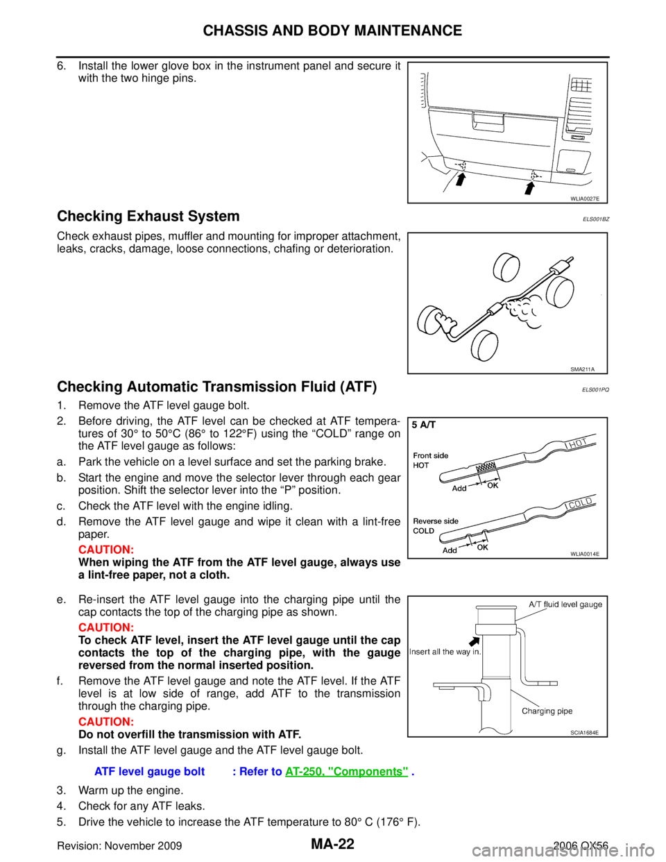
6. Install the lower glove box in the instrument panel and secure it
with the two hinge pins.
Checking Exhaust SystemELS001BZ
Check exhaust pipes, muffler and mounting for improper attachment,
leaks, cracks, damage, loose connections, chafing or deterioration.
Checking Automatic Transmission Fluid (ATF)ELS001PQ
1. Remove the ATF level gauge bolt.
2. Before driving, the ATF level can be checked at ATF tempera-tures of 30 ° to 50 °C (86 ° to 122 °F) using the “COLD” range on
the ATF level gauge as follows:
a. Park the vehicle on a level surface and set the parking brake.
b. Start the engine and move the selector lever through each gear position. Shift the selector lever into the “P” position.
c. Check the ATF level with the engine idling.
d. Remove the ATF level gauge and wipe it clean with a lint-free paper.
CAUTION:
When wiping the ATF from the ATF level gauge, always use
a lint-free paper, not a cloth.
e. Re-insert the ATF level gauge into the charging pipe until the cap contacts the top of the charging pipe as shown.
CAUTION:
To check ATF level, insert the ATF level gauge until the cap
contacts the top of the charging pipe, with the gauge
reversed from the normal inserted position.
f. Remove the ATF level gauge and note the ATF level. If the ATF level is at low side of range, add ATF to the transmission
through the charging pipe.
CAUTION:
Do not overfill the transmission with ATF.
g. Install the ATF level gauge and the ATF level gauge bolt.
3. Warm up the engine.
4. Check for any ATF leaks.
5. Drive the vehicle to increase the ATF temperature to 80 ° C (176 ° F).
WLIA0027E
SMA211A
WLIA0014E
ATF level gauge bolt : Refer to AT- 2 5 0 , "Components" .
SCIA1684E
Page 2635 of 3383

PB-4
PARKING BRAKE CONTROL
Revision: November 20092006 QX56
PARKING BRAKE CONTROLPFP:36010
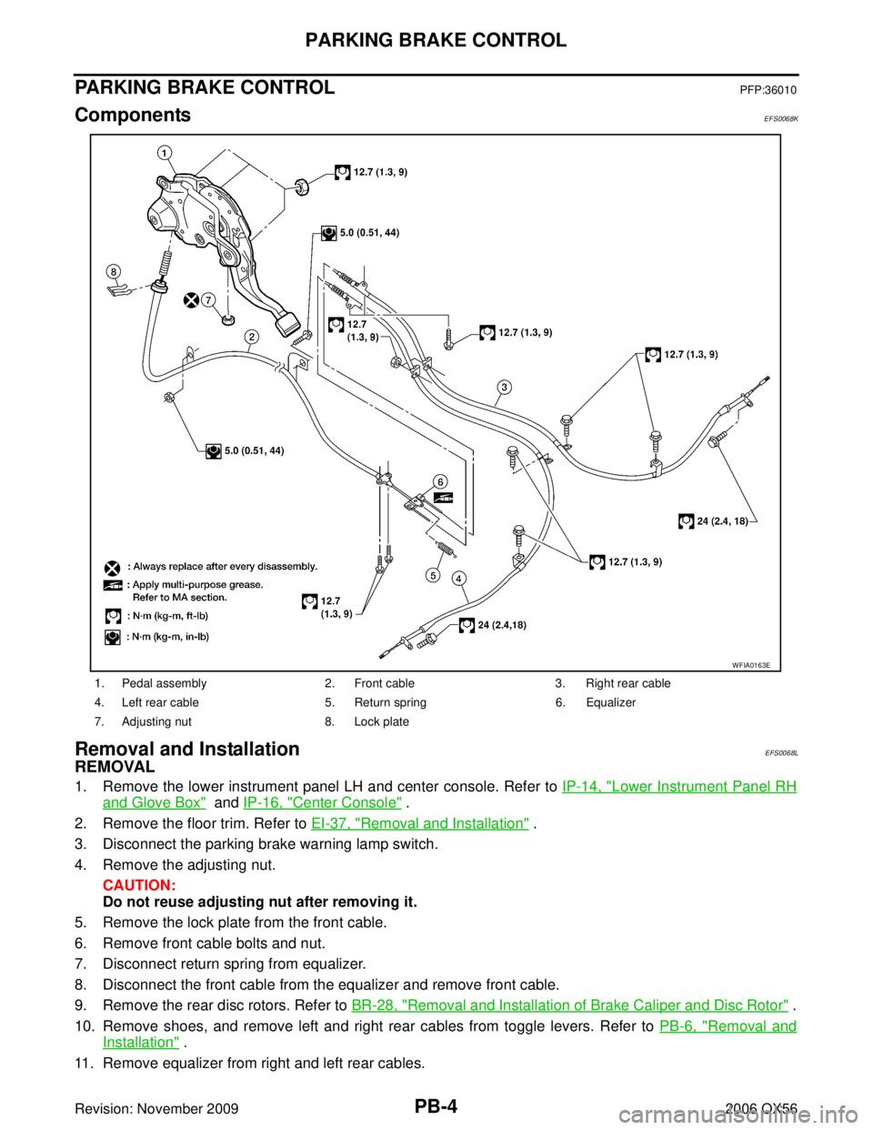
ComponentsEFS0068K
Removal and InstallationEFS0068L
REMOVAL
1. Remove the lower instrument panel LH and center console. Refer to IP-14, "Lower Instrument Panel RH
and Glove Box" and IP-16, "Center Console" .
2. Remove the floor trim. Refer to EI-37, "
Removal and Installation" .
3. Disconnect the parking brake warning lamp switch.
4. Remove the adjusting nut. CAUTION:
Do not reuse adjusting nut after removing it.
5. Remove the lock plate from the front cable.
6. Remove front cable bolts and nut.
7. Disconnect return spring from equalizer.
8. Disconnect the front cable from the equalizer and remove front cable.
9. Remove the rear disc rotors. Refer to BR-28, "
Removal and Installation of Brake Caliper and Disc Rotor" .
10. Remove shoes, and remove left and right rear cables from toggle levers. Refer to PB-6, "
Removal and
Installation" .
11. Remove equalizer from right and left rear cables.
1. Pedal assembly 2. Front cable 3. Right rear cable
4. Left rear cable 5. Return spring 6. Equalizer
7. Adjusting nut 8. Lock plate
WFIA0163E
Page 3091 of 3383

SRS-50
FRONT PASSENGER AIR BAG MODULE
Revision: November 20092006 QX56
FRONT PASSENGER AIR BAG MODULEPFP:K8515
Removal and InstallationEHS0016Z
The passenger air bag module originally installed in the vehicle uses direct-connect style harness connectors.
Service replacement passenger air bag modules use tab-locking style harness connectors. If the passenger
air bag module is replaced or if the direct-connect harness connectors are damaged, the vehicle wiring har-
ness must be modified to allow connection of the service replacement passenger air bag module. Refer to
SRS-51, "
WIRING HARNESS MODIFICATION" for wiring harness modification procedure.
REMOVAL
CAUTION:
�Do not attempt to repair or replace damaged direct-connect front passenger air bag module con-
nectors. If a direct-connect harness connector is damaged, the front passenger air bag must be
replaced and the wiring harness modified.
�Before servicing SRS, turn the ignition switch off, disconnect both battery cables and wait at least
3 minutes.
�Always work from the side of or under front passenger air bag module.
1. Remove the glove box. Refer to IP-10, "
INSTRUMENT PANEL ASSEMBLY" .
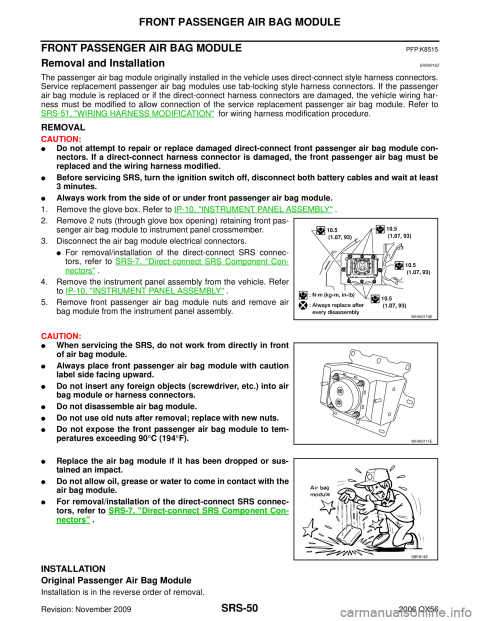
2. Remove 2 nuts (through glove box opening) retaining front pas- senger air bag module to instrument panel crossmember.
3. Disconnect the air bag module electrical connectors.
�For removal/installation of the direct-connect SRS connec-
tors, refer to SRS-7, "
Direct-connect SRS Component Con-
nectors" .
4. Remove the instrument panel assembly from the vehicle. Refer to IP-10, "
INSTRUMENT PANEL ASSEMBLY" .
5. Remove front passenger air bag module nuts and remove air bag module from the instrument panel assembly.
CAUTION:
�When servicing the SRS, do not work from directly in front
of air bag module.
�Always place front passenger air bag module with caution
label side facing upward.
�Do not insert any foreign objects (screwdriver, etc.) into air
bag module or harness connectors.
�Do not disassemble air bag module.
�Do not use old nuts after removal; replace with new nuts.
�Do not expose the front passenger air bag module to tem-
peratures exceeding 90 °C (194 °F).
�Replace the air bag module if it has been dropped or sus-
tained an impact.
�Do not allow oil, grease or water to come in contact with the
air bag module.
�For removal/installation of the direct-connect SRS connec-
tors, refer to SRS-7, "
Direct-connect SRS Component Con-
nectors" .
INSTALLATION
Original Passenger Air Bag Module
Installation is in the reverse order of removal.
WHIA0110E
W H I A 0 111 E
SBF814E
Page 3237 of 3383

TF-132
TRANSFER CONTROL UNIT
Revision: November 20092006 QX56
TRANSFER CONTROL UNITPFP:33084
Removal and InstallationEDS002IS
REMOVAL
1. Set transfer state as 2WD when 4WD shift switch is at 2WD, or as AUTO when 4WD shift switch is at
AUTO.
CAUTION:
When removing transfer control unit, transfer state must be at 2WD or AUTO.
2. Turn the ignition switch OFF and disconnect negative battery terminal.
3. Remove the glove box assembly. Refer to IP-14, "
Lower Instrument Panel RH and Glove Box" .
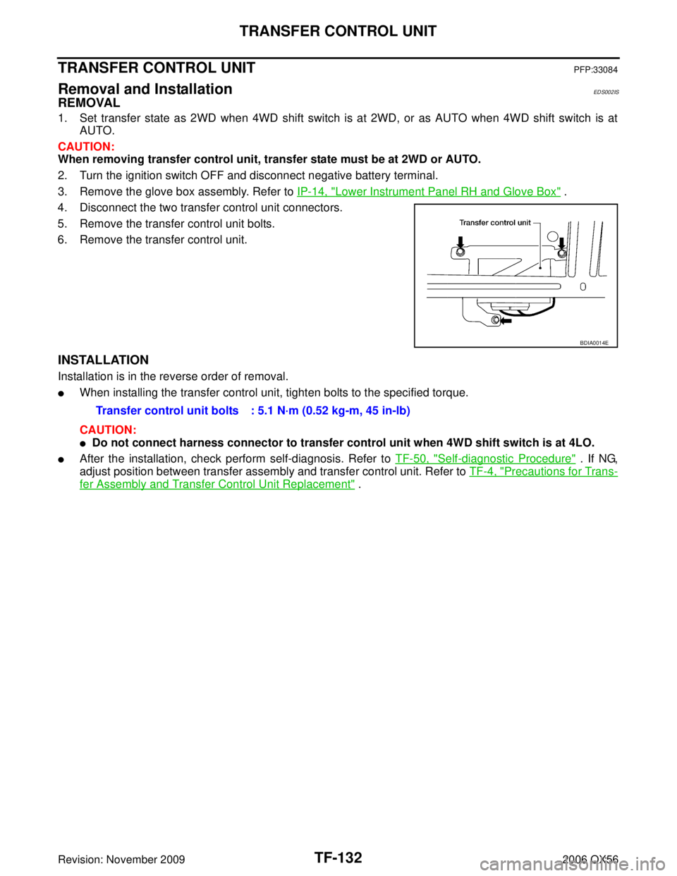
4. Disconnect the two transfer control unit connectors.
5. Remove the transfer control unit bolts.
6. Remove the transfer control unit.
INSTALLATION
Installation is in the reverse order of removal.
�When installing the transfer control unit, tighten bolts to the specified torque.
CAUTION:
�Do not connect harness connector to transfer control unit when 4WD shift switch is at 4LO.
�After the installation, check perform self-diagnosis. Refer to TF-50, "Self-diagnostic Procedure" . If NG,
adjust position between transfer assembly and transfer control unit. Refer to TF-4, "
Precautions for Trans-
fer Assembly and Transfer Control Unit Replacement" .
BDIA0014E
Transfer control unit bolts : 5.1 N·m (0.52 kg-m, 45 in-lb)
Page:
< prev 1-8 9-16 17-24