Page 3183 of 3383

TF-78
TROUBLE DIAGNOSIS FOR SYSTEM
Revision: November 20092006 QX56
DIAGNOSTIC PROCEDURE
1. CHECK ACTUATOR POSITION SWITCH SIGNAL
With CONSULT-II
1. Start engine.
2. Select “DATA MONITOR ” mode for “ALL MODE AWD/4WD ” with CONSULT-II.
3. Read out the value of “SHIFT POS SW1” and “SHIFT POS
SW2 ”.
Without CONSULT-II
1. Start engine.
2. Check voltage between transfer control unit harness connector terminal and ground.
OK or NG
OK >> GO TO 5.
NG >> GO TO 2.
Monitored item ConditionDisplay value
SHIFT POS SW1
�Vehicle stopped
�Engine running
�A/T selector lever
“ N ” position
�Brake pedal
depressed 4WD shift switch: 4LO ON
4WD shift switch:
2WD, AUTO or 4H
OFF
SHIFT POS SW2
�Vehicle stopped
�Engine running
�A/T selector lever
“ N ” position
�Brake pedal
depressed 4WD shift switch: 4H,
AUTO or 2WD
ON
4WD shift switch: 4LO OFF
Connector Terminal ConditionVoltage
(Approx.)
E143 27 -
Ground
�Vehicle stopped
�Engine running
�A/T selector
lever “N ” position
�Brake pedal
depressed 4WD shift switch: 4H,
AUTO or 2WD
0V
4WD shift switch: 4LO Battery
voltage
44 -
Ground
�Vehicle stopped
�Engine running
�A/T selector
lever “N ” position
�Brake pedal
depressed 4WD shift switch: 4LO 0V
4WD shift switch:
2WD, AUTO or 4H
Battery
voltage
SDIA2714E
SDIA2715E
Page 3192 of 3383
TROUBLE DIAGNOSIS FOR SYSTEMTF-87
CE F
G H
I
J
K L
M A
B
TF
Revision: November 2009 2006 QX56
DIAGNOSTIC PROCEDURE
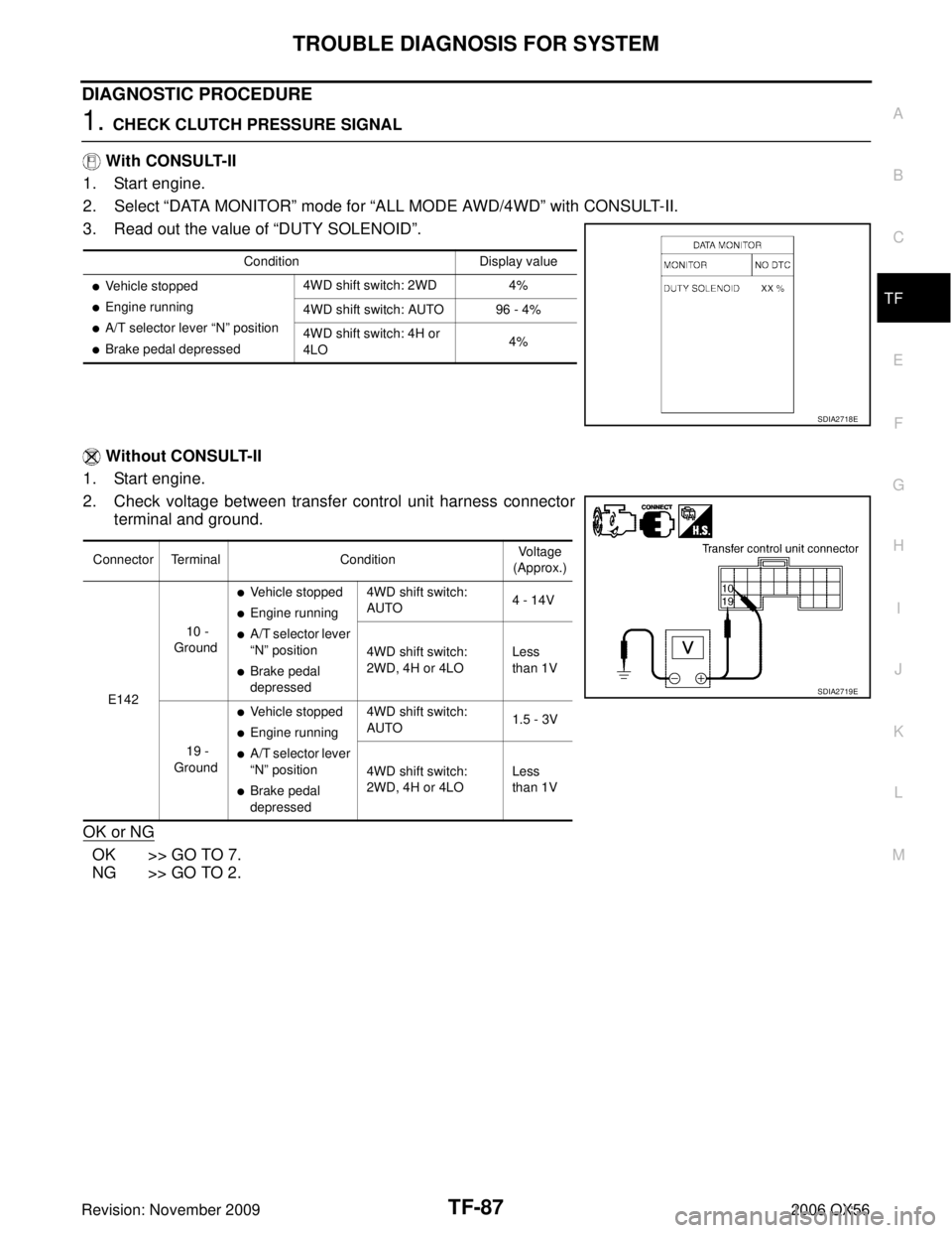
1. CHECK CLUTCH PRESSURE SIGNAL
With CONSULT-II
1. Start engine.
2. Select “DATA MONITOR ” mode for “ALL MODE AWD/4WD ” with CONSULT-II.
3. Read out the value of “DUTY SOLENOID”.
Without CONSULT-II
1. Start engine.
2. Check voltage between transfer control unit harness connector terminal and ground.
OK or NG
OK >> GO TO 7.
NG >> GO TO 2.
Condition Display value
�Vehicle stopped
�Engine running
�A/T selector lever “N” position
�Brake pedal depressed 4WD shift switch: 2WD 4%
4WD shift switch: AUTO 96 - 4%
4WD shift switch: 4H or
4LO
4%
SDIA2718E
Connector Terminal
ConditionVoltage
(Approx.)
E142 10 -
Ground
�Vehicle stopped
�Engine running
�A/T selector lever
“ N ” position
�Brake pedal
depressed 4WD shift switch:
AUTO
4 - 14V
4WD shift switch:
2WD, 4H or 4LO Less
than 1V
19 -
Ground
�Vehicle stopped
�Engine running
�A/T selector lever
“ N ” position
�Brake pedal
depressed 4WD shift switch:
AUTO
1.5 - 3V
4WD shift switch:
2WD, 4H or 4LO Less
than 1V
SDIA2719E
Page 3197 of 3383
TF-92
TROUBLE DIAGNOSIS FOR SYSTEM
Revision: November 20092006 QX56
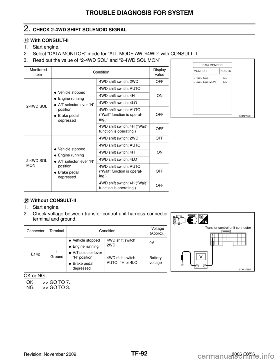
2. CHECK 2-4WD SHIFT SOLENOID SIGNAL
With CONSULT-II
1. Start engine.
2. Select “DATA MONITOR ” mode for “ALL MODE AWD/4WD ” with CONSULT-II.
3. Read out the value of “2-4WD SOL” and “2-4WD SOL MON ”.
Without CONSULT-II
1. Start engine.
2. Check voltage between transfer control unit harness connector terminal and ground.
OK or NG
OK >> GO TO 7.
NG >> GO TO 3.
Monitored item Condition Display
value
2-4WD SOL
�Vehicle stopped
�Engine running
�A/T selector lever “N ”
position
�Brake pedal
depressed 4WD shift switch: 2WD OFF
4WD shift switch: AUTO
ON
4WD shift switch: 4H
4WD shift switch: 4LO
4WD shift switch: AUTO
( “Wait ” function is operat-
ing.) OFF
4WD shift switch: 4H ( “Wait ”
function is operating.) OFF
2-4WD SOL
MON
�Vehicle stopped
�Engine running
�A/T selector lever “N ”
position
�Brake pedal
depressed 4WD shift switch: 2WD OFF
4WD shift switch: AUTO
ON
4WD shift switch: 4H
4WD shift switch: 4LO
4WD shift switch: AUTO
( “Wait ” function is operat-
ing.) OFF
4WD shift switch: 4H ( “Wait ”
function is operating.) OFF
SDIA2727E
Connector Terminal
ConditionVoltage
(Approx.)
E142 1 -
Ground
�Vehicle stopped
�Engine running
�A/T selector lever
“ N ” position
�Brake pedal
depressed 4WD shift switch:
2WD
0V
4WD shift switch:
AUTO, 4H or 4LO Battery
voltage
SDIA2728E
Page 3202 of 3383
TROUBLE DIAGNOSIS FOR SYSTEMTF-97
CE F
G H
I
J
K L
M A
B
TF
Revision: November 2009 2006 QX56
DIAGNOSTIC PROCEDURE
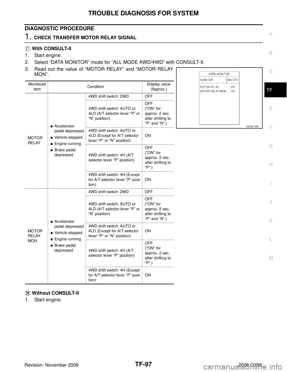
1. CHECK TRANSFER MOTOR RELAY SIGNAL
With CONSULT-II
1. Start engine.
2. Select “DATA MONITOR ” mode for “ALL MODE AWD/4WD ” with CONSULT-II.
3. Read out the value of “MOTOR RELAY” and “MOTOR RELAY
MON ”.
Without CONSULT-II
1. Start engine.
Monitored item Condition Display value
(Approx.)
MOTOR
RELAY
�Accelerator
pedal depressed
�Vehicle stopped
�Engine running
�Brake pedal
depressed 4WD shift switch: 2WD OFF
4WD shift switch: AUTO or
4LO (A/T selector lever
“P ” or
“ N ” position) OFF
("ON" for
approx. 2 sec.
after shifting to
“
P ” and “ N”.)
4WD shift switch: AUTO or
4LO (Except for A/T selector
lever “P ” or “N ” position) ON
4WD shift switch: 4H (A/T
selector lever “P ” position) OFF
("ON" for
approx. 2 sec.
after shifting to
“
P ”.)
4WD shift switch: 4H (Except
for A/T selector lever “ P” posi-
tion) ON
MOTOR
RELAY
MON
�Accelerator
pedal depressed
�Vehicle stopped
�Engine running
�Brake pedal
depressed 4WD shift switch: 2WD OFF
4WD shift switch: AUTO or
4LO (A/T selector lever
“P ” or
“ N ” position) OFF
("ON" for
approx. 2 sec.
after shifting to
“
P ” and “ N”.)
4WD shift switch: AUTO or
4LO (Except for A/T selector
lever “P ” or “N ” position) ON
4WD shift switch: 4H (A/T
selector lever “P ” position) OFF
("ON" for
approx. 2 sec.
after shifting to
“
P ”.)
4WD shift switch: 4H (Except
for A/T selector lever “ P” posi-
tion) ON
SDIA2734E
Page 3218 of 3383
TROUBLE DIAGNOSIS FOR SYSTEMTF-113
CE F
G H
I
J
K L
M A
B
TF
Revision: November 2009 2006 QX56
CAN Communication LineEDS002IQ
DIAGNOSTIC PROCEDURE
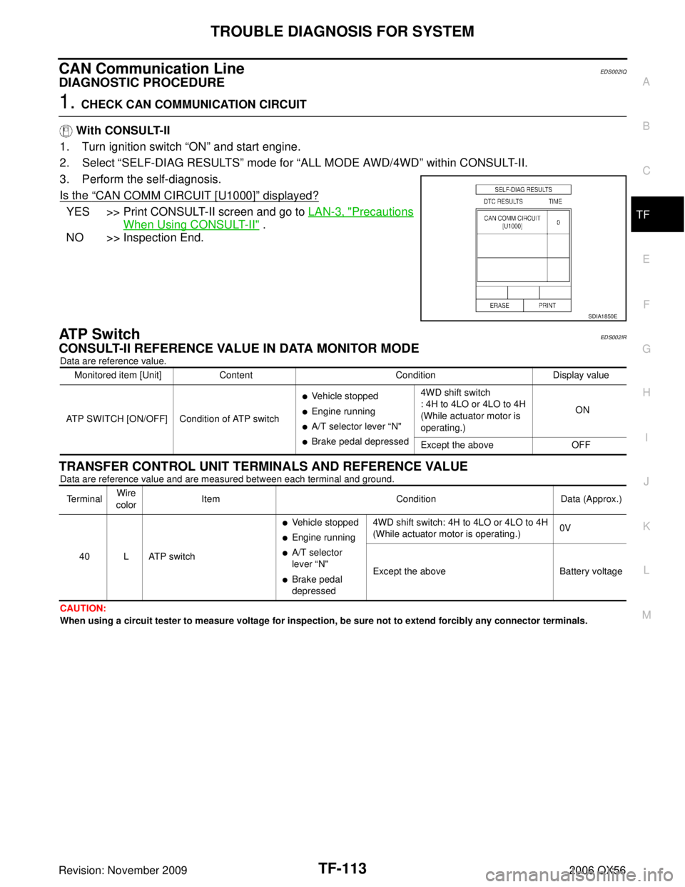
1. CHECK CAN COMMUNICATION CIRCUIT
With CONSULT-II
1. Turn ignition switch “ON” and start engine.
2. Select “SELF-DIAG RESULTS ” mode for “ALL MODE AWD/4WD ” within CONSULT-II.
3. Perform the self-diagnosis.
Is the
“CAN COMM CIRCUIT [U1000]” displayed?
YES >> Print CONSULT-II screen and go to LAN-3, "Precautions
When Using CONSULT-II" .
NO >> Inspection End.
ATP SwitchEDS002IR
CONSULT-II REFERENCE VALUE IN DATA MONITOR MODE
Data are reference value.
TRANSFER CONTROL UNIT TERMINALS AND REFERENCE VALUE
Data are reference value and are measured between each terminal and ground.
CAUTION:
When using a circuit tester to measure voltage for inspection, be sure not to extend forcibly any connector terminals.
SDIA1850E
Monitored item [Unit] Content ConditionDisplay value
ATP SWITCH [ON/OFF] Condition of ATP switch
�Vehicle stopped
�Engine running
�A/T selector lever “ N"
�Brake pedal depressed 4WD shift switch
: 4H to 4LO or 4LO to 4H
(While actuator motor is
operating.)
ON
Except the above OFF
TerminalWire
color Item
ConditionData (Approx.)
40 L ATP switch
�Vehicle stopped
�Engine running
�A/T selector
lever “N"
�Brake pedal
depressed 4WD shift switch: 4H to 4LO or 4LO to 4H
(While actuator motor is operating.)
0V
Except the above Battery voltage
Page 3219 of 3383
TF-114
TROUBLE DIAGNOSIS FOR SYSTEM
Revision: November 20092006 QX56
DIAGNOSTIC PROCEDURE
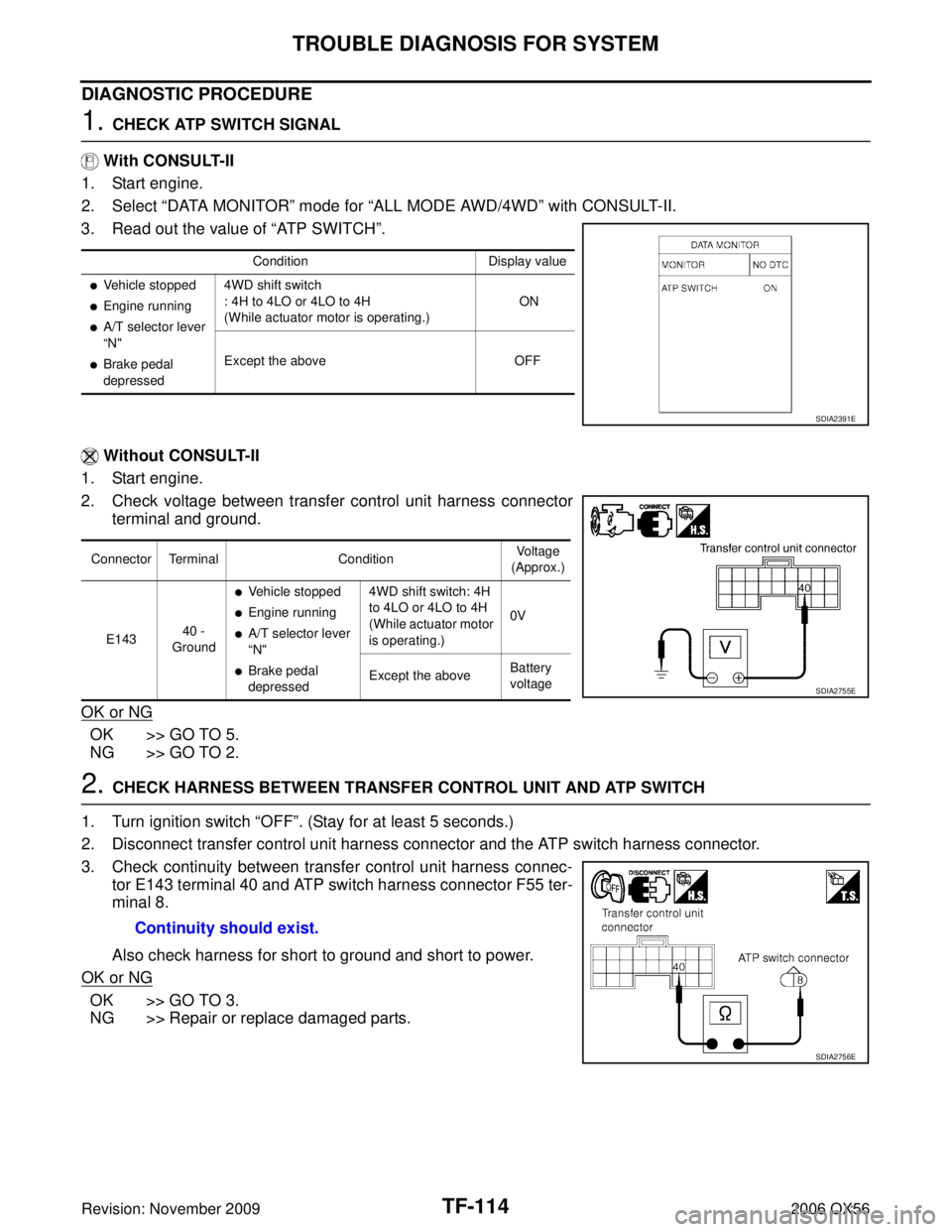
1. CHECK ATP SWITCH SIGNAL
With CONSULT-II
1. Start engine.
2. Select “DATA MONITOR ” mode for “ALL MODE AWD/4WD ” with CONSULT-II.
3. Read out the value of “AT P S W I T C H”.
Without CONSULT-II
1. Start engine.
2. Check voltage between transfer control unit harness connector terminal and ground.
OK or NG
OK >> GO TO 5.
NG >> GO TO 2.
2. CHECK HARNESS BETWEEN TRANSFER CONTROL UNIT AND ATP SWITCH
1. Turn ignition switch “ OFF”. (Stay for at least 5 seconds.)
2. Disconnect transfer control unit harness connector and the ATP switch harness connector.
3. Check continuity between transfer control unit harness connec- tor E143 terminal 40 and ATP switch harness connector F55 ter-
minal 8.
Also check harness for short to ground and short to power.
OK or NG
OK >> GO TO 3.
NG >> Repair or replace damaged parts.
Condition Display value
�Vehicle stopped
�Engine running
�A/T selector lever
“N"
�Brake pedal
depressed 4WD shift switch
: 4H to 4LO or 4LO to 4H
(While actuator motor is operating.)
ON
Except the above OFF
SDIA2391E
Connector TerminalConditionVoltage
(Approx.)
E143 40 -
Ground
�Vehicle stopped
�Engine running
�A/T selector lever
“ N"
�Brake pedal
depressed 4WD shift switch: 4H
to 4LO or 4LO to 4H
(While actuator motor
is operating.)
0V
Except the above Battery
voltage
SDIA2755E
Continuity should exist.
SDIA2756E
Page 3247 of 3383
TF-142
TRANSFER MOTOR
Revision: November 20092006 QX56
TRANSFER MOTORPFP:00000
Removal and InstallationEDS003BD
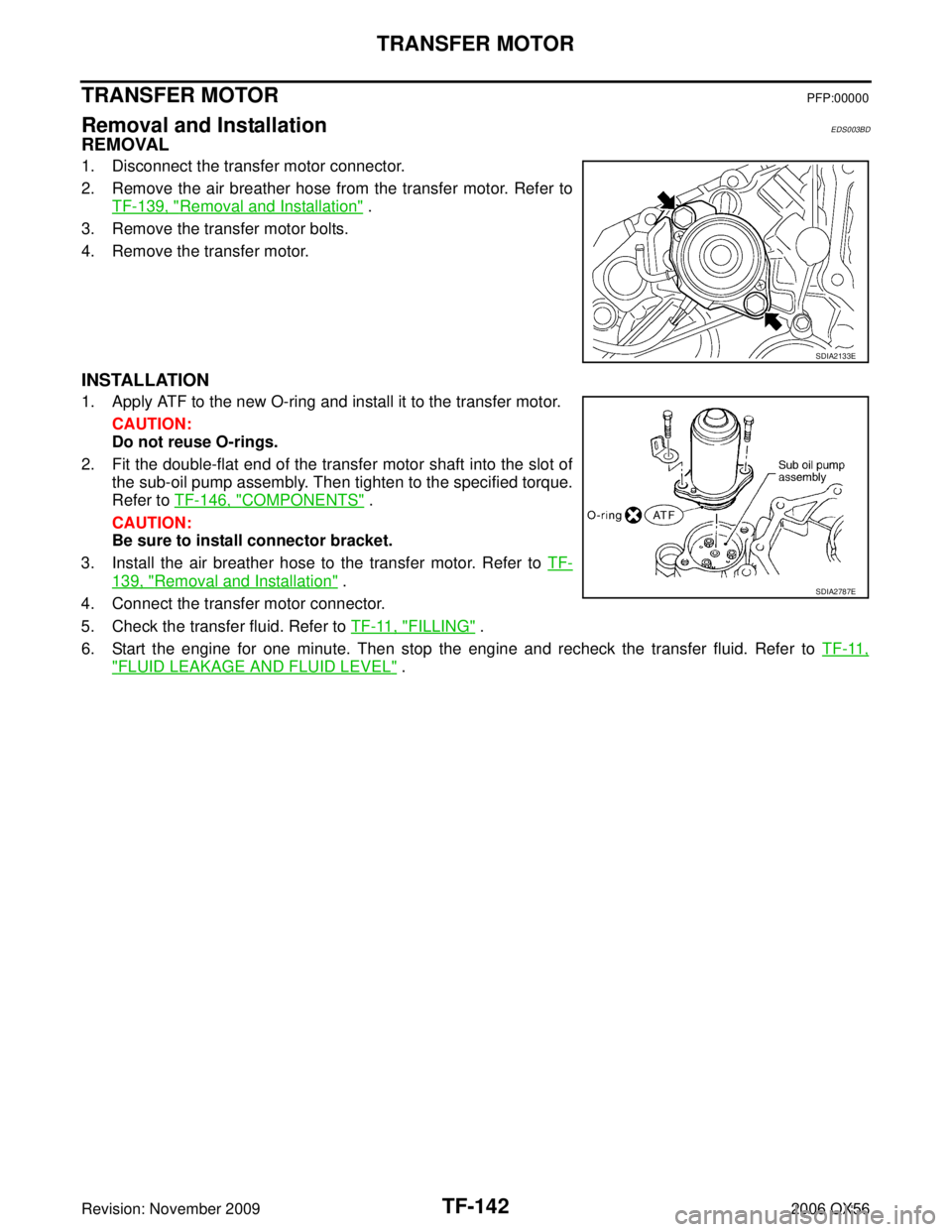
REMOVAL
1. Disconnect the transfer motor connector.
2. Remove the air breather hose from the transfer motor. Refer to
TF-139, "
Removal and Installation" .
3. Remove the transfer motor bolts.
4. Remove the transfer motor.
INSTALLATION
1. Apply ATF to the new O-ring and install it to the transfer motor.
CAUTION:
Do not reuse O-rings.
2. Fit the double-flat end of the transfer motor shaft into the slot of the sub-oil pump assembly. Then tighten to the specified torque.
Refer to TF-146, "
COMPONENTS" .
CAUTION:
Be sure to install connector bracket.
3. Install the air breather hose to the transfer motor. Refer to TF-
139, "Removal and Installation" .
4. Connect the transfer motor connector.
5. Check the transfer fluid. Refer to TF-11, "
FILLING" .
6. Start the engine for one minute. Then stop the engine and recheck the transfer fluid. Refer to TF-11,
"FLUID LEAKAGE AND FLUID LEVEL" .
SDIA2133E
SDIA2787E
Page 3249 of 3383
TF-144
TRANSFER OIL FILTER
Revision: November 20092006 QX56
3. Apply ATF to the two new O-rings (1), and install them on the oil
filter (2).
CAUTION:
Do not reuse O-rings.
4. Install the oil filter to the transfer assembly. Tighten the bolts to the specified torque. Refer to TF-146, "
COMPONENTS" .
CAUTION:
�Do not damage oil filter.
�Attach oil filter and tighten bolts evenly.
5. Check the transfer fluid. Refer to TF-11, "
TRANSFER FLUID" .
6. Start the engine and let it run for one minute. Then stop the engine and recheck the transfer fluid. Refer to TF-11, "
TRANS-
FER FLUID" .
WDIA0285E
SDIA2136E