Page 2534 of 3383
")
TRAILER TOWLT-127
C
DE
F
G H
I
J
L
M A
B
LT
Revision: November 2009 2006 QX56
�through IPDM E/R terminal 61
�to trailer tow relay 1 terminal 3, and
�through 20A fuse (No. 53, located in the IPDM E/R)
�to CPU (central processing unit) of the IPDM E/R, and
�through 30A fusible link (letter j , located in the fuse and fusible link box)
�to trailer tow relay 2 terminals 3 and 6, and
�through 40A fusible link (letter k , located in the fuse and fusible link box)
�to electric brake (pre-wiring) terminal 5.
With the ignition switch in the ON or START position, power is supplied
�to ignition relay, located in the IPDM E/R, and
�through 10A fuse (No. 59, located in the fuse and relay box)
�to BCM terminal 38, and
�through 10A fuse (No. 51, located in the IPDM E/R)
�to trailer tow relay 2 terminal 1.
Ground is supplied
�to BCM terminal 67
�to electric brake (pre-wiring) terminal 1, and
�through grounds M57, M61 and M79, and
�to IPDM E/R terminals 38 and 59
�to trailer tow relay 1 terminal 2
�to trailer tow relay 2 terminal 2, and
�to trailer connector terminal 2
�to trailer turn relay LH and RH terminal 2
�through grounds E9, E15 and E24.
TRAILER TAIL LAMP OPERATION
The trailer tail lamps are controlled by the trailer tow relay 1.
With the lighting switch in the parking and tail lamp ON (1ST) position, AUTO position (and the auto light sys-
tem is activated) or headlamp ON (2ND) position, power is supplied
�through the tail lamp relay, located in the IPDM E/R
�through 10A fuse (No. 36, located in the IPDM E/R)
�through IPDM E/R terminal 49
�to trailer tow relay 1 terminal 1.
When energized, trailer tow relay 1 supplies tail lamp power to trailer connector terminal 6.
TRAILER BRAKE, TURN SIGNAL AND HAZARD LAMP OPERATION
The trailer brake, turn signal and hazard lamps are controlled by the BCM through trailer turn relays (LH and
RH). When the brake pedal is depressed, the BCM receives stop lamp switch signal through CAN communi-
cation. If the brake pedal is depressed or either turn signal or the hazard lamps are turned on, the BCM sup-
plies voltage to the trailer turn relays (LH and RH) to make them cycle on and off.
Trailer turn relay LH output is supplied
�through BCM terminal 52
�to trailer turn relay LH terminal 1.
Trailer turn relay RH output is supplied
�through BCM terminal 51
�to trailer turn relay RH terminal 1.
Left trailer brake, turn signal and hazard lamp output is supplied
�through trailer turn relay LH terminal 3
�to trailer connector terminal 1.
Right trailer brake, turn signal and hazard lamp output is supplied
�through trailer turn relay RH terminal 3
Page 2535 of 3383
LT-128
TRAILER TOW
Revision: November 20092006 QX56
�to trailer connector terminal 4.
TRAILER BRAKE OPERATION
The trailer brake is controlled by the electric brake. The electric brake receives stop lamp switch signal at elec-
tric brake (pre-wiring) terminal 2 when the brake pedal is depressed.
When the brake pedal is depressed, power is supplied by the electric brake
�through electric brake (pre-wiring) terminal 3
�to trailer connector terminal 3.
TRAILER POWER SUPPLY OPERATION
The trailer power supply is controlled by the trailer tow relay 2.
When the ignition switch is in the ON or START position, power is supplied
�through 10A fuse (No. 51, located in the IPDM E/R)
�through IPDM E/R terminal 16
�to trailer tow relay 2 terminal 1.
When energized, the trailer tow relay 2 supplies power
�through trailer tow relay 2 terminals 5 and 7
�to trailer connector terminal 5.
Page 2557 of 3383

LT-150
INTERIOR ROOM LAMP
Revision: November 20092006 QX56
4. Touch "INT LAMP" on "SELECT TEST ITEM" screen.
WORK SUPPORT
Operation Procedure
1. Touch "INT LAMP" on "SELECT TEST ITEM" screen.
2. Touch "WORK SUPPORT" on "SELECT DIAG MODE" screen.
3. Touch "SET I/L D-UNLCK INTCON" on "SELECT WORK ITEM" screen.
4. Touch "START".
5. Touch "CHANGE SETT".
6. The setting will be changed and "CUSTOMIZING COMPLETED" will be displayed.
7. Touch "END".
Display Item List
Reference between "MODE" and "TIME" for "TURN ON/OFF".
DATA MONITOR
Operation Procedure
1. Touch "INT LAMP" on "SELECT TEST ITEM" screen.
2. Touch "DATA MONITOR" on "SELECT DIAG MODE" screen.
3. Touch either "ALL SIGNALS" or "SELECTION FROM MENU" on "SELECT MONITOR ITEM" screen.
4. Touch "START".
5. When "SELECTION FROM MENU" is selected, touch items to be monitored. When "ALL SIGNALS" is
selected, all the items will be monitored.
6. Touch "RECORD" while monitoring, then the status of the monitored item can be recorded. To stop recording, touch "STOP".
PKIA5226E
Item Description CONSULT-II
SET I/L D-UNLCK INTCON The 30 seconds operating function of the interior room lamps and the
ignition keyhole illumination can be selected when front door LH is
released (unlocked). ON/OFF
ROOM LAMP ON TIME SET The time in order to escalate illumination can be adjusted when the
interior room lamps and the ignition keyhole illumination is turned on. MODE 1 - 7
ROOM LAMP OFF TIME SET The time in order to diminish illumination can be adjusted when the
interior room lamps and the ignition keyhole illumination is turned off. MODE 1 - 7
MODE 1 2 3 4 5 6 7
Time (sec.) 0.5 1 2 3 4 5 0
All signals Monitors all the signals.
Selection from menu Selects and monitors the individual signal.
Page 2591 of 3383

LU-8Revision: November 2009
ENGINE OIL
2006 QX56
5. Install Tools.
6. Start the engine and warm it up to normal operating temperature.
7. Check the engine oil pressure with engine running under no-load.Engine oil pressure [Engine oil temperature at 80 °C (175 °F)]
Unit: kPa (kg/cm2
, psi)
CAUTION:
If the difference is extreme, check the oil passages and oil pump for leaks and blockages.
8. After the inspections, install oil pressure sensor as follows:
a. Remove old liquid gasket adhering to oil pressure sensor and engine.
b. Apply liquid gasket and tighten oil pressure sensor to the specification. Use Genuine RTV Silicone Sealant or equivalent. Refer to GI-46, "
Recommended Chemical Prod-
ucts and Sealants" .
c. After warming up engine, make sure there is no leakage of engine oil with engine running.
Changing Engine OilEBS00LMT
CAUTION:
�Be careful not to burn yourself, as the engine oil is hot.
�Prolonged and repeated contact with used engine oil may
cause skin cancer; try to avoid direct skin contact with
used engine oil. If skin contact is made, wash thoroughly
with soap or hand cleaner as soon as possible.
1. Remove engine front undercover using power tool.
2. Warm up engine, and check for oil leakage from engine compo- nents. Refer to LU-7, "
OIL LEAKAGE" .
3. Stop engine and wait for 10 minutes.
4. Loosen oil filler cap, then remove drain plug.
5. Drain engine oil.
6. Install drain plug with new washer.
CAUTION:
�Be sure to clean drain plug and install with new washer.
7. Refill with new engine oil. Refer to MA-11, "
Fluids and Lubricants" .
Tool number : ST25051001 (J-25695-1)
: ST25052000 (J-25695-2)
WBIA0571E
Engine Speed Approximate Discharge Pressure
Idle speed More than 98 (1.0, 14)
2,000 rpm More than 294 (3.0, 43)
Oil pressure sensor torque : 14.7 N·m (1.5 kg-m, 11 ft-lb)
Oil pan drain plug : 34.3 N·m (3.5 kg-m, 25 ft-lb)
KBIA2498E
Page 2593 of 3383

LU-10Revision: November 2009
OIL FILTER
2006 QX56
OIL FILTERPFP:15208
Removal and InstallationEBS00LMU
REMOVAL
1. Remove the engine front undercover using power tool.
2. Remove the oil filter using Tool.WARNING:
�The oil filter is provided with a relief valve.
Use Genuine NISSAN oil filter or equivalent.
�When removing, prepare a shop cloth to absorb any
engine oil leakage or spillage.
�Do not allow engine oil to adhere to the drive belts.
�Completely wipe off any engine oil that adheres to the
engine and the vehicle.
CAUTION:
�Be careful not to get burned when the engine and engine oil are hot.
INSTALLATION
1. Remove foreign materials adhering to the oil filter installation surface.
2. Apply engine oil to the oil seal circumference of the new oil filter.
3. Screw the oil filter manually until it touches the installation sur- face, then tighten it by 2/3 turn. Or tighten to specification.
4. Inspect the engine for oil leakage. Refer to LU-10, "
INSPEC-
TION AFTER INSTALLATION" .
5. Install the engine front undercover using power tool.
INSPECTION AFTER INSTALLATION
1. Check the engine oil level. Refer to LU-7, "OIL LEVEL" .
2. Start the engine and check for engine oil leakage.
3. Stop the engine and wait for 10 minutes.
4. Check the engine oil level and add engine oil as required. Tool number : KV10115801 (J-38956)
WBIA0388E
SMA010
Oil filter : 17.7 N·m (1.8 kg-m, 13 ft-lb)
SMA229B
Page 2595 of 3383
LU-12Revision: November 2009
OIL COOLER
2006 QX56
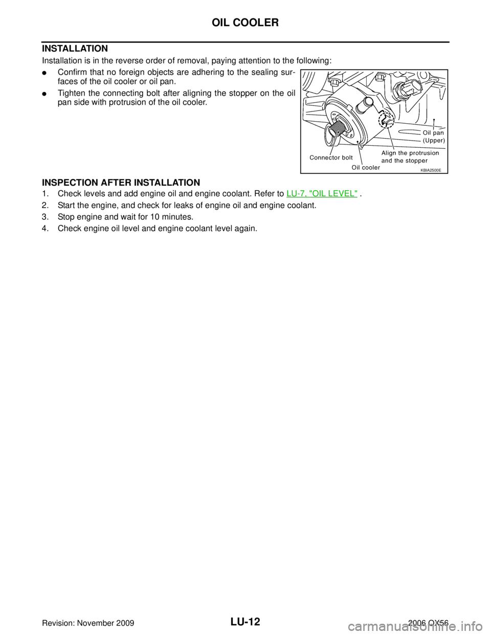
INSTALLATION
Installation is in the reverse order of removal, paying attention to the following:
�Confirm that no foreign objects are adhering to the sealing sur-
faces of the oil cooler or oil pan.
�Tighten the connecting bolt after aligning the stopper on the oil
pan side with protrusion of the oil cooler.
INSPECTION AFTER INSTALLATION
1. Check levels and add engine oil and engine coolant. Refer to LU-7, "OIL LEVEL" .
2. Start the engine, and check for leaks of engine oil and engine coolant.
3. Stop engine and wait for 10 minutes.
4. Check engine oil level and engine coolant level again.
KBIA2500E
Page 2597 of 3383

LU-14Revision: November 2009
OIL PUMP
2006 QX56
INSPECTION AFTER INSTALLATION
�Start the engine, and check for leaks of engine oil.
�Stop engine and wait 10 minutes.
�Check level and add engine oil as required. Refer to LU-7, "ENGINE OIL" .
Disassembly and AssemblyEBS00LMX
DISASSEMBLY
1. Remove oil pump cover.
2. Remove inner rotor and outer rotor from oil pump body.
3. Remove the regulator plug, regulator spring and regulator valve.
INSPECTION AFTER DISASSEMBLY
Clearance of Oil Pump Parts
�Measure radial clearance using a suitable tool.
�Measure side clearance using suitable tools.
�Calculate the clearance between inner rotor and oil pump body
as follows.
1. Measure the outer diameter of protruded portion of inner rotor (position 5) using suitable tool.Body to outer rotor (position 1)
: 0.114 - 0.200 mm (0.0045 - 0.0079 in)
Inner rotor to outer rotor tip (position 2)
: Below 0.180 mm (0.0071 in)
PBIC0139E
Body to inner rotor (position 3)
: 0.030 - 0.070 mm (0.0012 - 0.0028 in)
Body to outer rotor (position 4)
: 0.030 - 0.090 mm (0.0012 - 0.0035 in)
PBIC0140E
PBIC0141E
Page 2617 of 3383
MA-18
ENGINE MAINTENANCE
Revision: November 20092006 QX56
2. Apply clean engine oil to the oil filter seal circumference of the
new oil filter.
3. Screw the oil filter manually until it touches the installation sur- face, then tighten it by 2/3 turn. Or tighten to specification.
4. Inspect the engine for oil leaks. Refer to MA-18, "
INSPECTION
AFTER INSTALLATION" .
5. Install the engine front undercover using power tool.
INSPECTION AFTER INSTALLATION
1. Check the oil level using the dipstick as shown. Add oil as nec- essary.
CAUTION:
Do not overfill the engine with oil.
2. Start the engine and check for engine oil leaks.
3. Stop the engine and wait for 10 minutes.
4. Check the engine oil level and add engine oil as required.
Changing Spark PlugsELS001PN
SMA010
Oil filter : 17.7 N·m (1.8 kg-m, 13 ft-lb)
SMA229B
SMA954C
1. Ignition coil 2. Spark plug
WBIA0796E