Page 2301 of 3383
LAN-32
[CAN]
CAN COMMUNICATION
Revision: November 20092006 QX56
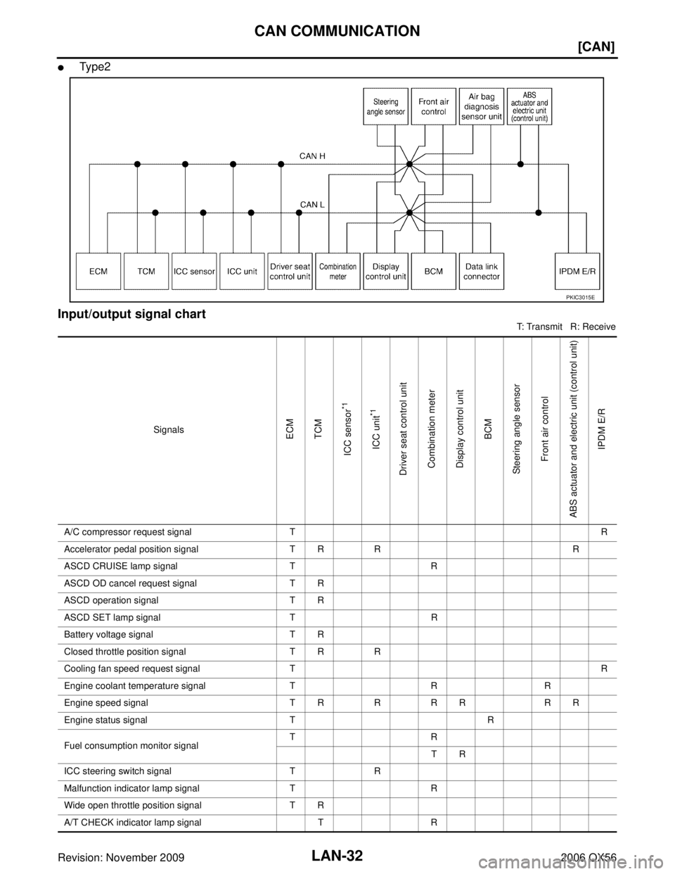
�Ty p e 2
Input/output signal chart
T: Transmit R: Receive
PKIC3015E
SignalsECM
TCM
ICC sensor
*1
ICC unit
*1
Driver seat control unit Combination meter
Display control unit BCM
Steering angle sensor Front air control
ABS actuator and electric unit (control unit) IPDM E/R
A/C compressor request signal T R
Accelerator pedal position signal T RR R
ASCD CRUISE lamp signal TR
ASCD OD cancel request signal T R
ASCD operation signal T R
ASCD SET lamp signal TR
Battery voltage signal T R
Closed throttle position signal T R R
Cooling fan speed request signal T R
Engine coolant temperature signal TRR
Engine speed signal T RRR R R R
Engine status signal TR
Fuel consumption monitor signal TR
TR
ICC steering switch signal TR
Malfunction indicator lamp signal TR
Wide open throttle position signal T R
A/T CHECK indicator lamp signal TR
Page 2305 of 3383
![INFINITI QX56 2006 Factory Service Manual LAN-36
[CAN]
CAN COMMUNICATION
Revision: November 20092006 QX56
ASCD CRUISE lamp signalTR
ASCD OD cancel request signal T R
ASCD operation signal T R
ASCD SET lamp signal TR
Battery voltage signal T R](/manual-img/42/57028/w960_57028-2304.png "INFINITI QX56 2006 Factory Service Manual LAN-36
[CAN]
CAN COMMUNICATION
Revision: November 20092006 QX56
ASCD CRUISE lamp signalTR
ASCD OD cancel request signal T R
ASCD operation signal T R
ASCD SET lamp signal TR
Battery voltage signal T R")
LAN-36
[CAN]
CAN COMMUNICATION
Revision: November 20092006 QX56
ASCD CRUISE lamp signalTR
ASCD OD cancel request signal T R
ASCD operation signal T R
ASCD SET lamp signal TR
Battery voltage signal T R
Closed throttle position signal T R R
Cooling fan speed request signal T R
Engine coolant temperature signal TRR
Engine speed signal T RRR R R R R
Engine status signal TR
Fuel consumption monitor signal TR
TR
ICC steering switch signal TR
Malfunction indicator lamp signal TR
Wide open throttle position signal T R
A/T CHECK indicator lamp signal TR
A/T fluid temperature sensor signal TR
A/T position indicator lamp signal TR R R
A/T self-diagnosis signal R T
Current gear position signal TR R
Output shaft revolution signal R TR R
P range signal TR R R
Turbine revolution signal R TR
ICC sensor signal T R
Buzzer output signal TR
RT
ICC OD cancel request signal R RT
ICC operation signal R RT
ICC system display signal TR
System setting signal TR
RT
1st position switch signal RT
4th position switch signal RT
Distance to empty signal T R
Signals
ECM
TCM
ICC sensor
*1
ICC unit
*1
Driver seat control unit Combination meter
Display control unit BCM
Steering angle sensor Front air control
Transfer control unit
ABS actuator and electric unit (control unit) IPDM E/R
Page 2436 of 3383
HEADLAMP (FOR USA)LT-29
C
DE
F
G H
I
J
L
M A
B
LT
Revision: November 2009 2006 QX56
Aiming AdjustmentEKS00B89
For details, refer to the regulations in your area.
NOTE:
If vehicle front body has been repaired and /or the headlamp assembly has been replaced, check headlamp
aiming.
HEADLAMP AIMING
NOTE:
�Before performing aiming adjustment, check the following:
–Confirm headlamp aiming switch is set to "0" (zero) position.
–Ensure all tires are inflated to correct pressure.
–Place vehicle and screen on level surface.
–Ensure there is no load in vehicle other than the driver (or equivalent weight placed in driver's position).
Coolant and engine oil filled to correct level, and fuel tank full.
–Confirm spare tire, jack and tools are properly stowed.
–Aim each headlamp individually and ensure other headlamp beam pattern is blocked from screen.
–Use adjusting screw to perform aiming adjustment
WKIA1859E
Page 2485 of 3383

LT-78
FRONT FOG LAMP
Revision: November 20092006 QX56
Aiming AdjustmentEKS00B9M
The fog lamp is a semi-sealed beam type which uses a replaceable halogen bulb. Before performing aiming
adjustment, make sure of the following.
�Keep all tires inflated to correct pressure.
�Place vehicle on level ground.
�See that vehicle is unloaded (except for full levels of coolant,
engine oil and fuel, and spare tire, jack, and tools). Have the
driver or equivalent weight placed in driver seat.
Adjust aiming in the vertical direction by turning the adjustment
screw.
NOTE:
Access adjustment screw from underneath front bumper. Turn screw
clockwise to raise pattern and counterclockwise to lower pattern.
1. Set the distance between the screen and the center of the fog lamp lens as shown.
2. Turn front fog lamps ON.
3. Adjust front fog lamps using adjusting screw so that the top edge of the high intensity zone is 200 mm (7.9 in) below the height of
the fog lamp centers as shown.
�When performing adjustment, if necessary, cover the headlamps
and opposite fog lamp.
SEL350X
MEL327G
MEL328GA
Page 2585 of 3383

LU-2Revision: November 2009
PRECAUTIONS
2006 QX56
PRECAUTIONSPFP:00001
Precautions for Liquid GasketEBS00NIH
REMOVAL OF LIQUID GASKET SEALING
�After removing the bolts and nuts, separate the mating surface
and remove the old liquid gasket sealing using Tool.
CAUTION:
Do not damage the mating surfaces.
�Tap the seal cutter to insert it.
�In areas where the Tool is difficult to use, lightly tap to slide it.
LIQUID GASKET APPLICATION PROCEDURE
1. Remove the old liquid gasket adhering to the gasket applicationsurface and the mating surface using suitable tool.
�Remove the liquid gasket completely from the groove of the
liquid gasket application surface, bolts, and bolt holes.
2. Thoroughly clean the mating surfaces and remove adhering moisture, grease and foreign material.
3. Attach the liquid gasket tube to the Tool. Use Genuine RTV Silicone Sealant or equivalent. Refer to
GI-46, "
Recommended Chemical Products and Sealants" .
4. Apply the liquid gasket without breaks to the specified location with the specified dimensions.
�If there is a groove for the liquid gasket application, apply the
liquid gasket to the groove.
�As for the bolt holes, normally apply the liquid gasket inside
the holes. If specified in the procedure, it should also be
applied outside the holes.
�Within five minutes of liquid gasket application, install the mat-
ing component.
�If the liquid gasket protrudes, wipe it off immediately.
�Do not retighten after the installation.
�Wait 30 minutes or more after installation before refilling the
engine with engine oil and engine coolant.
CAUTION:
If there are specific instructions in this manual, observe them. Tool number
: KV10111100 (J-37228)
WBIA0566E
PBIC0003E
Tool number : WS39930000 ( — )
WBIA0567E
SEM159F
Page 2590 of 3383

ENGINE OILLU-7
C
DE
F
G H
I
J
K L
M A
LU
Revision: November 2009 2006 QX56
ENGINE OILPFP:KLA92
InspectionEBS00LMS
OIL LEVEL
�Before starting the engine make sure the vehicle is parked on a
flat and level surface, then check the oil level. If the engine is
already running, turn it off and allow 10 minutes before check-
ing.
�Check that the oil level is within the low (L) and high (H) range
as indicated on the dipstick.
�If the engine oil level is out of range, add oil as necessary. Refer
to GI-46, "
Recommended Chemical Products and Sealants" .
OIL APPEARANCE
�Check the engine oil for a white milky appearance or excessive contamination.
�If the engine oil is milky, it is highly probable that it is contaminated with engine coolant. Repair the broken
parts.
OIL LEAKAGE
Check for oil leakage around the following areas:
�Oil pan
�Oil pan drain plug
�Oil pressure sensor
�Oil filter
�Oil cooler
�Intake valve timing control cover
�Intake valve timing control solenoid valve
�Front cover
�Mating surface between cylinder block and cylinder head
�Mating surface between cylinder head and rocker cover
�Crankshaft oil seal (front and rear)
OIL PRESSURE CHECK
CAUTION:
�Be careful not to burn yourself, as engine oil may be hot.
�Put the selector lever in the Park “P” position.
1. Check the engine oil level. Refer to LU-7, "
OIL LEVEL" .
2. Remove engine front undercover using power tool.
3. Disconnect the oil pressure sensor harness connector.
4. Remove the oil pressure sensor.
SMA954C
WBIA0538E
Page 2594 of 3383

OIL COOLERLU-11
C
DE
F
G H
I
J
K L
M A
LU
Revision: November 2009 2006 QX56
OIL COOLERPFP:21305
Removal and InstallationEBS00LMV
CAUTION:
Be careful not to burn yourself, as the engine oil and engine coolant are hot.
REMOVAL
1. Remove engine front undercover using power tool.
2. Disconnect water hoses, pinching hoses near oil cooler to prevent engine coolant from spilling.
CAUTION:
Do not spill engine coolant on the drive belt.
3. Remove oil filter. Refer to LU-10, "
Removal and Installation" .
CAUTION:
Do not spill engine oil on the drive belts.
4. Remove connector bolt, and remove oil cooler.
INSPECTION AFTER REMOVAL
Oil Cooler
Check oil cooler for cracks. Check oil cooler for clogging by blowing compressed air through engine coolant
inlet. If necessary, replace oil cooler assembly.
Relief Valve
Inspect relief valve for movement, cracks and breaks by pushing the ball. If replacement is necessary, remove
valve by prying it out using a suitable tool. Install a new valve in place by tapping it.
WBIA0414E
1. Oil pan 2. Water hose3. Water pipe
4. Water hose 5. Oil cooler bolt6. Oil filter
7. Oil cooler 8. O-ring9. Relief valve
10. Water hose 11. Connector pipe12. Gasket
Page 2595 of 3383
LU-12Revision: November 2009
OIL COOLER
2006 QX56
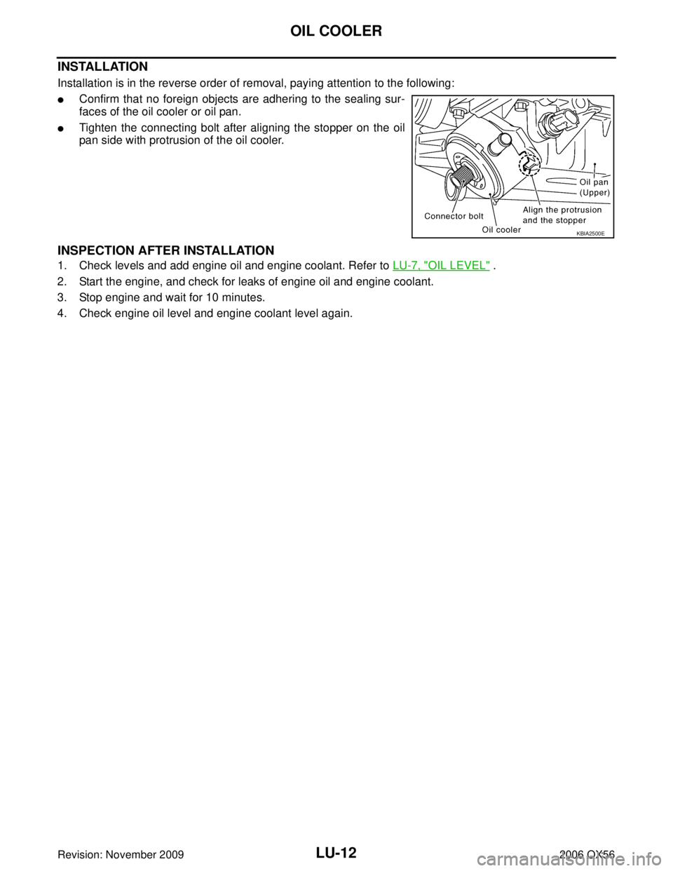
INSTALLATION
Installation is in the reverse order of removal, paying attention to the following:
�Confirm that no foreign objects are adhering to the sealing sur-
faces of the oil cooler or oil pan.
�Tighten the connecting bolt after aligning the stopper on the oil
pan side with protrusion of the oil cooler.
INSPECTION AFTER INSTALLATION
1. Check levels and add engine oil and engine coolant. Refer to LU-7, "OIL LEVEL" .
2. Start the engine, and check for leaks of engine oil and engine coolant.
3. Stop engine and wait for 10 minutes.
4. Check engine oil level and engine coolant level again.
KBIA2500E
LT-29
C
DE
F
G H
I
J
L
M A
B
LT
Revision: November 2009 2006 QX56
Aiming AdjustmentEKS00B89
For details, refer to the regulations in your area.
NOTE:
If vehicle front body has been r")