Page 2962 of 3383

AUTOMATIC DRIVE POSITIONERSE-31
C
DE
F
G H
J
K L
M A
B
SE
Revision: November 2009 2006 QX56
Preliminary CheckEIS004XN
SETTING CHANGE FUNCTION
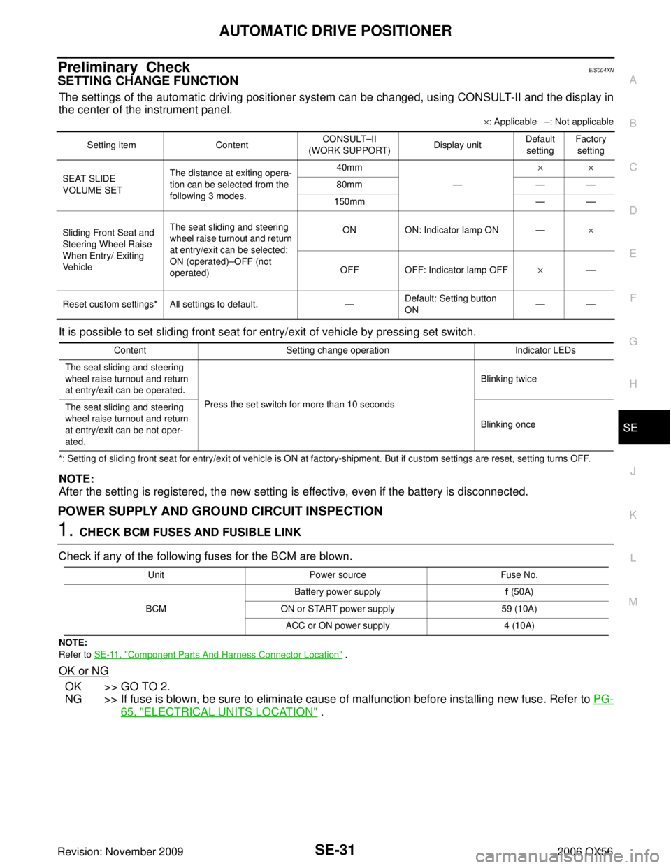
The settings of the automatic driving positioner system can be changed, using CONSULT-II and the display in
the center of the instrument panel.
×: Applicable –: Not applicable
It is possible to set sliding front seat for entry/exit of vehicle by pressing set switch.
*: Setting of sliding front seat for entry/exit of vehicle is ON at factory-shipment. But if custom settings are reset, setting turns OFF.
NOTE:
After the setting is registered, the new setting is effective, even if the battery is disconnected.
POWER SUPPLY AND GROUND CIRCUIT INSPECTION
1. CHECK BCM FUSES AND FUSIBLE LINK
Check if any of the following fuses for the BCM are blown.
NOTE:
Refer to SE-11, "
Component Parts And Harness Connector Location" .
OK or NG
OK >> GO TO 2.
NG >> If fuse is blown, be sure to eliminate cause of malfunction before installing new fuse. Refer to PG-
65, "ELECTRICAL UNITS LOCATION" .
Setting item ContentCONSULT
–II
(WORK SUPPORT) Display unitDefault
setting Factory
setting
SEAT SLIDE
VOLUME SET The distance at exiting opera-
tion can be selected from the
following 3 modes. 40mm
—××
80mm ——
150mm ——
Sliding Front Seat and
Steering Wheel Raise
When Entry/ Exiting
Vehicle The seat sliding and steering
wheel raise turnout and return
at entry/exit can be selected:
ON (operated)
–OFF (not
operated) ON
ON: Indicator lamp ON —×
OFF OFF: Indicator lamp OFF ×—
Reset custom settings* All settings to default. —Default: Setting button
ON ——
Content
Setting change operation Indicator LEDs
The seat sliding and steering
wheel raise turnout and return
at entry/exit can be operated. Press the set switch for more than 10 seconds Blinking twice
The seat sliding and steering
wheel raise turnout and return
at entry/exit can be not oper-
ated. Blinking once
Unit
Power source Fuse No.
BCM Battery power supply
f (50A)
ON or START power supply 59 (10A)
ACC or ON power supply 4 (10A)
Page 3139 of 3383

TF-34
TROUBLE DIAGNOSIS
Revision: November 20092006 QX56
2. CHECK TIGHT CORNER BRAKING SYMPTOM (1)
1. Set 4WD shift switch to “AUTO” position.
2. Drive vehicle at speed lower than 20 km/h (12 MPH) with steering wheel fully turned.
Does tight corner braking symptom occur?
YES >> GO TO TF-130, "Heavy Tight-corner Braking Symptom Occurs" .
NO >> GO TO 3.
3. CHECK TIGHT CORNER BRAKING SYMPTOM (2)
1. Set 4WD shift switch to “4HI” position.
2. Drive vehicle at speed lower than 20 km/h (12 MPH) with steering wheel fully turned.
Does tight corner braking symptom occur?
YES >> Inspection End.
NO >> GO TO TF-131, "
4WD System Does Not Operate" .
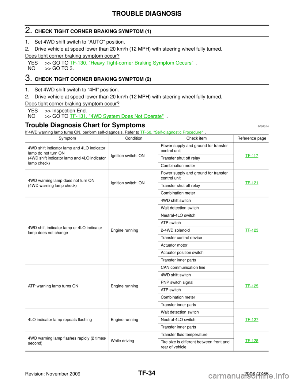
Trouble Diagnosis Chart for SymptomsEDS002HI
If 4WD warning lamp turns ON, perform self-diagnosis. Refer to TF-50, "Self-diagnostic Procedure" .
Symptom ConditionCheck itemReference page
4WD shift indicator lamp and 4LO indicator
lamp do not turn ON
(4WD shift indicator lamp and 4LO indicator
lamp check) Ignition switch: ONPower supply and ground for transfer
control unit
TF-117
Transfer shut off relay
Combination meter
4WD warning lamp does not turn ON
(4WD warning lamp check) Ignition switch: ONPower supply and ground for transfer
control unit
TF-121
Transfer shut off relay
Combination meter
4WD shift indicator lamp or 4LO indicator
lamp does not change Engine running4WD shift switch
TF-123
Wait detection switch
Neutral-4LO switch
AT P s w i t c h
2-4WD solenoid
Transfer control device
Actuator motor
Actuator position switch
Transfer inner parts
ATP warning lamp turns ON Engine running CAN communication line
TF-125
4WD shift switch
PNP switch signal
AT P s w i t c h
Combination meter
Transfer inner parts
4LO indicator lamp repeats flashing Engine running Wait detection switch
TF-127
Neutral-4LO switch
Transfer inner parts
4WD warning lamp flashes rapidly (2 times/
second) While drivingTransfer fluid temperature
TF-128
Tire size is different between front and
rear of vehicle
Page 3140 of 3383

TROUBLE DIAGNOSISTF-35
CE F
G H
I
J
K L
M A
B
TF
Revision: November 2009 2006 QX56
NOTE:
�Light tight-corner braking symptom may occur depending on driving conditions in AUTO mode. This is not
a malfunction.
�Heavy tight-corner braking symptom occurs when vehicle is driven in the following conditions: 4WD shift
switch is "4H" or "4LO", steering wheel is turned fully to either side.
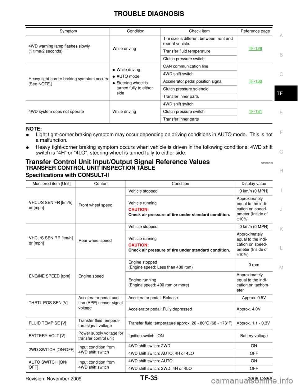
Transfer Control Unit Input/Output Signal Reference ValuesEDS002HJ
TRANSFER CONTROL UNIT INSPECTION TABLE
Specifications with CONSULT-II
4WD warning lamp flashes slowly
(1 time/2 seconds)While drivingTire size is different between front and
rear of vehicle.
TF-129
Transfer fluid temperature
Clutch pressure switch
Heavy tight-corner braking symptom occurs
(See NOTE.)
�While driving
�AUTO mode
�Steering wheel is
turned fully to either
side CAN communication line
TF-130
4WD shift switch
Accelerator pedal position signal
Clutch pressure solenoid
Transfer inner parts
4WD system does not operate While driving 4WD shift switch
TF-131
Clutch pressure switch
Transfer inner parts
Symptom
ConditionCheck itemReference page
Monitored item [Unit] Content ConditionDisplay value
VHCL/S SEN ·FR [km/h]
or [mph] Front wheel speed Vehicle stopped
0 km/h (0 MPH)
Vehicle running
CAUTION:
Check air pressure of tire under standard condition. Approximately
equal to the indi-
cation on speed-
ometer (Inside of
±
10%)
VHCL/S SEN ·RR [km/h]
or [mph] Rear wheel speed Vehicle stopped
0 km/h (0 MPH)
Vehicle running
CAUTION:
Check air pressure of tire under standard condition. Approximately
equal to the indi-
cation on speed-
ometer (Inside of
±
10%)
ENGINE SPEED [rpm] Engine speed Engine stopped
(Engine speed: Less than 400 rpm)
0 rpm
Engine running
(Engine speed: 400 rpm or more) Approximately
equal to the indi-
cation on tachom-
eter
THRTL POS SEN [V] Accelerator pedal posi-
tion (APP) sensor signal
voltage Accelerator pedal: Release
Approx. 0.5V
Accelerator pedal: Fully depressed Approx. 4.0V
FLUID TEMP SE [V] Transfer fluid tempera-
ture signal voltage Transfer fluid temperature approx. 20 - 80°C (68 - 176
°F) Approx. 1.1 - 0.3V
BATTERY VOLT [V] Power supply voltage for
transfer control unit
Ignition switch: ON
Battery voltage
2WD SWITCH [ON/OFF] Input condition from
4WD shift switch 4WD shift switch: 2WD
ON
4WD shift switch: AUTO, 4H or 4LO OFF
AUTO SWITCH [ON/
OFF] Input condition from
4WD shift switch 4WD shift switch: AUTO
ON
4WD shift switch: 2WD, 4H or 4LO OFF