Page 3609 of 5621
GW-90
REAR WINDOW DEFOGGER
Revision: 2006 January2006 M35/M45
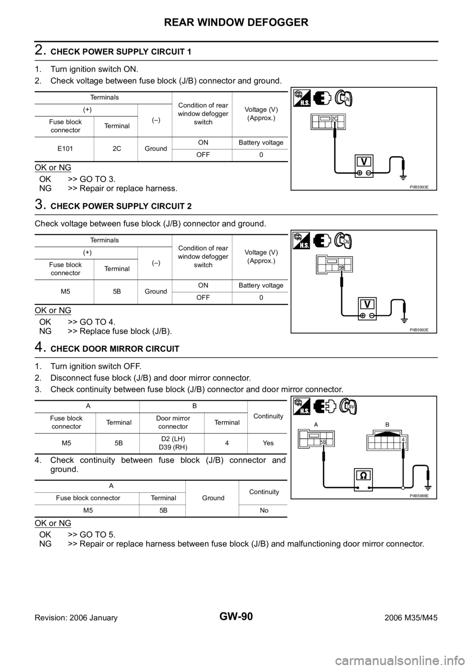
2. CHECK POWER SUPPLY CIRCUIT 1
1. Turn ignition switch ON.
2. Check voltage between fuse block (J/B) connector and ground.
OK or NG
OK >> GO TO 3.
NG >> Repair or replace harness.
3. CHECK POWER SUPPLY CIRCUIT 2
Check voltage between fuse block (J/B) connector and ground.
OK or NG
OK >> GO TO 4.
NG >> Replace fuse block (J/B).
4. CHECK DOOR MIRROR CIRCUIT
1. Turn ignition switch OFF.
2. Disconnect fuse block (J/B) and door mirror connector.
3. Check continuity between fuse block (J/B) connector and door mirror connector.
4. Check continuity between fuse block (J/B) connector and
ground.
OK or NG
OK >> GO TO 5.
NG >> Repair or replace harness between fuse block (J/B) and malfunctioning door mirror connector.
Terminals
Condition of rear
window defogger
switchVoltage (V)
(Approx.) (+)
(–)
Fuse block
connectorTerminal
E101 2C GroundON Battery voltage
OFF 0
PIIB5993E
Terminals
Condition of rear
window defogger
switchVoltage (V)
(Approx.) (+)
(–)
Fuse block
connectorTerminal
M5 5B GroundON Battery voltage
OFF 0
PIIB5992E
AB
Continuity
Fuse block
connectorTe r m i n a lDoor mirror
connectorTerminal
M5 5BD2 (LH)
D39 (RH)4Yes
A
GroundContinuity
Fuse block connector Terminal
M5 5B No
PIIB5988E
Page 3610 of 5621
REAR WINDOW DEFOGGER
GW-91
C
D
E
F
G
H
J
K
L
MA
B
GW
Revision: 2006 January2006 M35/M45
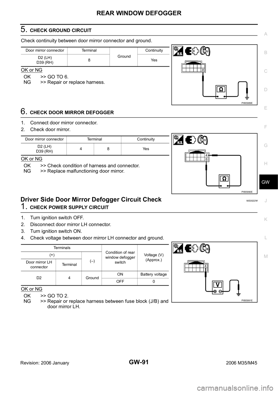
5. CHECK GROUND CIRCUIT
Check continuity between door mirror connector and ground.
OK or NG
OK >> GO TO 6.
NG >> Repair or replace harness.
6. CHECK DOOR MIRROR DEFOGGER
1. Connect door mirror connector.
2. Check door mirror.
OK or NG
OK >> Check condition of harness and connector.
NG >> Replace malfunctioning door mirror.
Driver Side Door Mirror Defogger Circuit CheckNIS0022W
1. CHECK POWER SUPPLY CIRCUIT
1. Turn ignition switch OFF.
2. Disconnect door mirror LH connector.
3. Turn ignition switch ON.
4. Check voltage between door mirror LH connector and ground.
OK or NG
OK >> GO TO 2.
NG >> Repair or replace harness between fuse block (J/B) and
door mirror LH.
Door mirror connector Terminal
GroundContinuity
D2 (LH)
D39 (RH)8Yes
PIIB5989E
Door mirror connector Terminal Continuity
D2 (LH)
D39 (RH)48 Yes
PIIB5990E
Te r m i n a l s
Condition of rear
window defogger
switchVoltage (V)
(Approx.) (+)
(–)
Door mirror LH
connectorTe r m i n a l
D2 4 GroundON Battery voltage
OFF 0
PIIB5991E
Page 3611 of 5621
GW-92
REAR WINDOW DEFOGGER
Revision: 2006 January2006 M35/M45
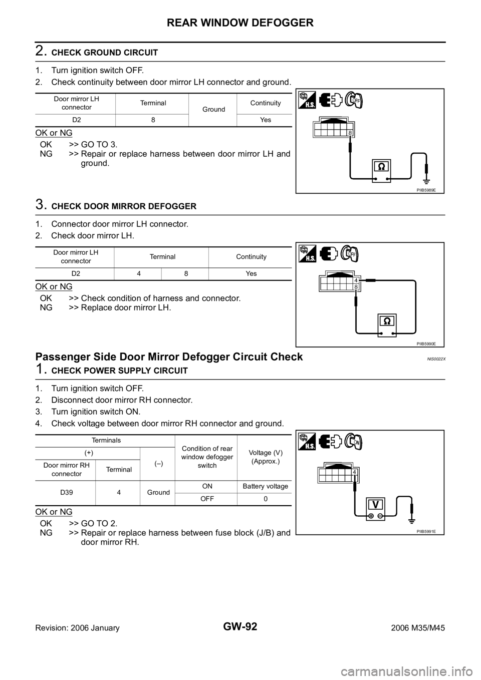
2. CHECK GROUND CIRCUIT
1. Turn ignition switch OFF.
2. Check continuity between door mirror LH connector and ground.
OK or NG
OK >> GO TO 3.
NG >> Repair or replace harness between door mirror LH and
ground.
3. CHECK DOOR MIRROR DEFOGGER
1. Connector door mirror LH connector.
2. Check door mirror LH.
OK or NG
OK >> Check condition of harness and connector.
NG >> Replace door mirror LH.
Passenger Side Door Mirror Defogger Circuit Check NIS0022X
1. CHECK POWER SUPPLY CIRCUIT
1. Turn ignition switch OFF.
2. Disconnect door mirror RH connector.
3. Turn ignition switch ON.
4. Check voltage between door mirror RH connector and ground.
OK or NG
OK >> GO TO 2.
NG >> Repair or replace harness between fuse block (J/B) and
door mirror RH.
Door mirror LH
connectorTerminal
GroundContinuity
D2 8 Yes
PIIB5989E
Door mirror LH
connectorTerminal Continuity
D2 4 8 Yes
PIIB5990E
Terminals
Condition of rear
window defogger
switchVoltage (V)
(Approx.) (+)
(–)
Door mirror RH
connectorTerminal
D39 4 GroundON Battery voltage
OFF 0
PIIB5991E
Page 3613 of 5621
GW-94
REAR WINDOW DEFOGGER
Revision: 2006 January2006 M35/M45
Filament CheckNIS0022Y
1. When measuring voltage, wrap tin foil around the top of the neg-
ative probe. Then press the foil against the wire with your finger.
2. Attach probe circuit tester (in Volt range) to middle portion of
each filament.
3. If a filament is burned out, circuit tester registers 0 or battery
voltage.
4. To locate burned out point, move probe to left and right along fil-
ament. Test needle will swing abruptly when probe passes the
point.
Filament RepairNIS0022Z
REPAIR EQUIPMENT
Conductive silver composition (Dupont No. 4817 or equivalent)
Ruler 30 cm (11.8 in) long
Drawing pen
Heat gun
Alcohol
Cloth
SEL122R
SEL263
SEL265
Page 3623 of 5621
GW-104
REVERSE INTERLOCK DOOR MIRROR SYSTEM
Revision: 2006 January2006 M35/M45
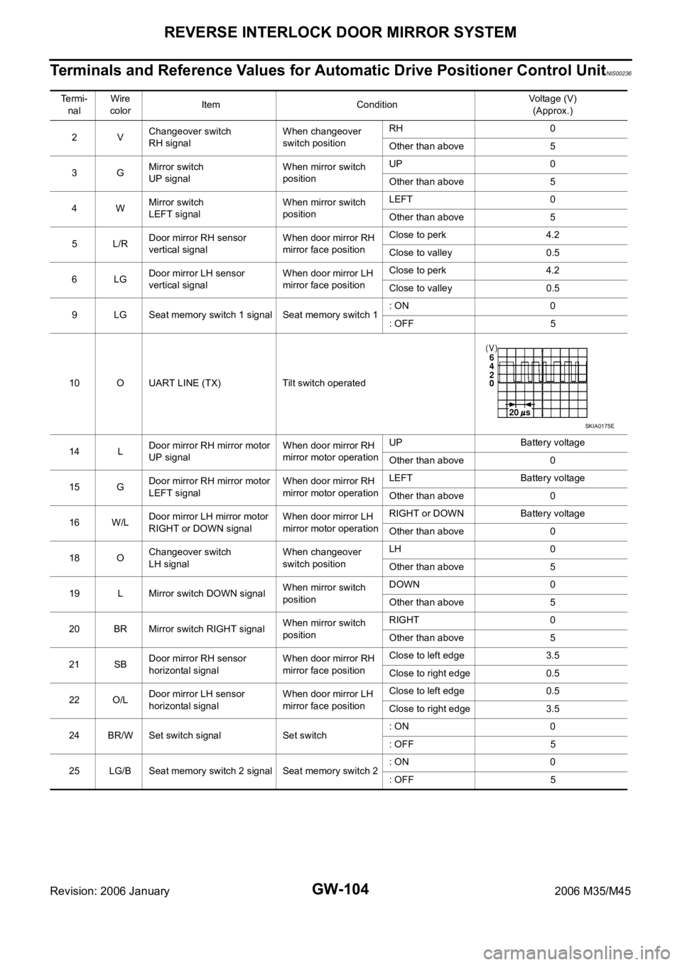
Terminals and Reference Values for Automatic Drive Positioner Control UnitNIS00236
Te r m i -
nalWire
colorItem ConditionVoltage (V)
(Approx.)
2VChangeover switch
RH signalWhen changeover
switch positionRH 0
Other than above 5
3GMirror switch
UP signalWhen mirror switch
positionUP 0
Other than above 5
4WMirror switch
LEFT signalWhen mirror switch
positionLEFT 0
Other than above 5
5L/RDoor mirror RH sensor
vertical signalWhen door mirror RH
mirror face positionClose to perk 4.2
Close to valley 0.5
6LGDoor mirror LH sensor
vertical signalWhen door mirror LH
mirror face positionClose to perk 4.2
Close to valley 0.5
9 LG Seat memory switch 1 signal Seat memory switch 1: ON 0
: OFF 5
10 O UART LINE (TX) Tilt switch operated
14 LDoor mirror RH mirror motor
UP signalWhen door mirror RH
mirror motor operationUP Battery voltage
Other than above 0
15 GDoor mirror RH mirror motor
LEFT signalWhen door mirror RH
mirror motor operationLEFT Battery voltage
Other than above 0
16 W/LDoor mirror LH mirror motor
RIGHT or DOWN signalWhen door mirror LH
mirror motor operationRIGHT or DOWN Battery voltage
Other than above 0
18 OChangeover switch
LH signalWhen changeover
switch positionLH 0
Other than above 5
19 L Mirror switch DOWN signalWhen mirror switch
positionDOWN 0
Other than above 5
20 BR Mirror switch RIGHT signalWhen mirror switch
positionRIGHT 0
Other than above 5
21 SBDoor mirror RH sensor
horizontal signalWhen door mirror RH
mirror face positionClose to left edge 3.5
Close to right edge 0.5
22 O/LDoor mirror LH sensor
horizontal signalWhen door mirror LH
mirror face positionClose to left edge 0.5
Close to right edge 3.5
24 BR/W Set switch signal Set switch: ON 0
: OFF 5
25 LG/B Seat memory switch 2 signal Seat memory switch 2: ON 0
: OFF 5
SKIA0175E
Page 3624 of 5621
REVERSE INTERLOCK DOOR MIRROR SYSTEM
GW-105
C
D
E
F
G
H
J
K
L
MA
B
GW
Revision: 2006 January2006 M35/M45
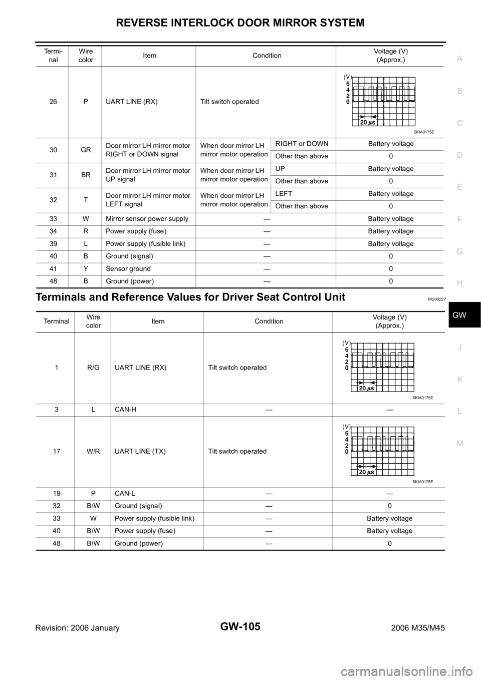
Terminals and Reference Values for Driver Seat Control UnitNIS00237
26 P UART LINE (RX) Tilt switch operated
30 GRDoor mirror LH mirror motor
RIGHT or DOWN signalWhen door mirror LH
mirror motor operationRIGHT or DOWN Battery voltage
Other than above 0
31 BRDoor mirror LH mirror motor
UP signalWhen door mirror LH
mirror motor operationUP Battery voltage
Other than above 0
32 TDoor mirror LH mirror motor
LEFT signalWhen door mirror LH
mirror motor operationLEFT Battery voltage
Other than above 0
33 W Mirror sensor power supply — Battery voltage
34 R Power supply (fuse) — Battery voltage
39 L Power supply (fusible link) — Battery voltage
40 B Ground (signal) — 0
41 Y Sensor ground — 0
48 B Ground (power) — 0 Termi-
nalWire
colorItem ConditionVoltage (V)
(Approx.)
SKIA0175E
Terminal Wire
colorItem ConditionVoltage (V)
(Approx.)
1 R/G UART LINE (RX) Tilt switch operated
3 L CAN-H — —
17 W/R UART LINE (TX) Tilt switch operated
19 P CAN-L — —
32 B/W Ground (signal) — 0
33 W Power supply (fusible link) — Battery voltage
40 B/W Power supply (fuse) — Battery voltage
48 B/W Ground (power) — 0
SKIA0175E
SKIA0175E
Page 3632 of 5621
REVERSE INTERLOCK DOOR MIRROR SYSTEM
GW-113
C
D
E
F
G
H
J
K
L
MA
B
GW
Revision: 2006 January2006 M35/M45
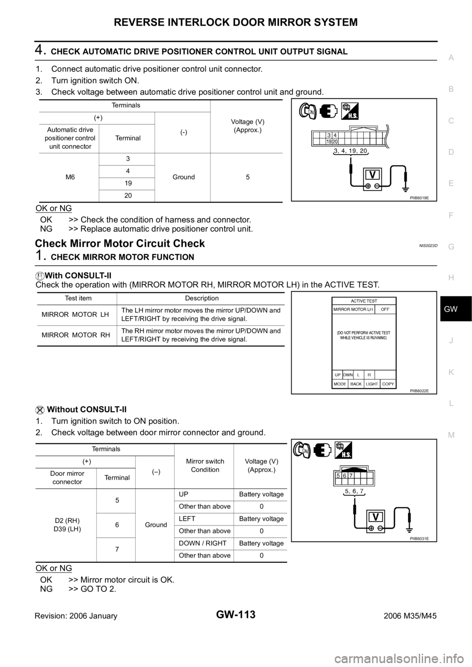
4. CHECK AUTOMATIC DRIVE POSITIONER CONTROL UNIT OUTPUT SIGNAL
1. Connect automatic drive positioner control unit connector.
2. Turn ignition switch ON.
3. Check voltage between automatic drive positioner control unit and ground.
OK or NG
OK >> Check the condition of harness and connector.
NG >> Replace automatic drive positioner control unit.
Check Mirror Motor Circuit CheckNIS0023D
1. CHECK MIRROR MOTOR FUNCTION
With CONSULT-II
Check the operation with (MIRROR MOTOR RH, MIRROR MOTOR LH) in the ACTIVE TEST.
Without CONSULT-II
1. Turn ignition switch to ON position.
2. Check voltage between door mirror connector and ground.
OK or NG
OK >> Mirror motor circuit is OK.
NG >> GO TO 2.
Terminals
Voltage (V)
(Approx.) (+)
(-) Automatic drive
positioner control
unit connectorTerminal
M63
Ground 5 4
19
20
PIIB6019E
Test item Description
MIRROR MOTOR LHThe LH mirror motor moves the mirror UP/DOWN and
LEFT/RIGHT by receiving the drive signal.
MIRROR MOTOR RHThe RH mirror motor moves the mirror UP/DOWN and
LEFT/RIGHT by receiving the drive signal.
PIIB6022E
Te r m i n a l s
Mirror switch
ConditionVoltage (V)
(Approx.) (+)
(–)
Door mirror
connectorTerminal
D2 (RH)
D39 (LH)5
GroundUP Battery voltage
Other than above 0
6LEFT Battery voltage
Other than above 0
7DOWN / RIGHT Battery voltage
Other than above 0
PIIB6031E
Page 3634 of 5621
REVERSE INTERLOCK DOOR MIRROR SYSTEM
GW-115
C
D
E
F
G
H
J
K
L
MA
B
GW
Revision: 2006 January2006 M35/M45
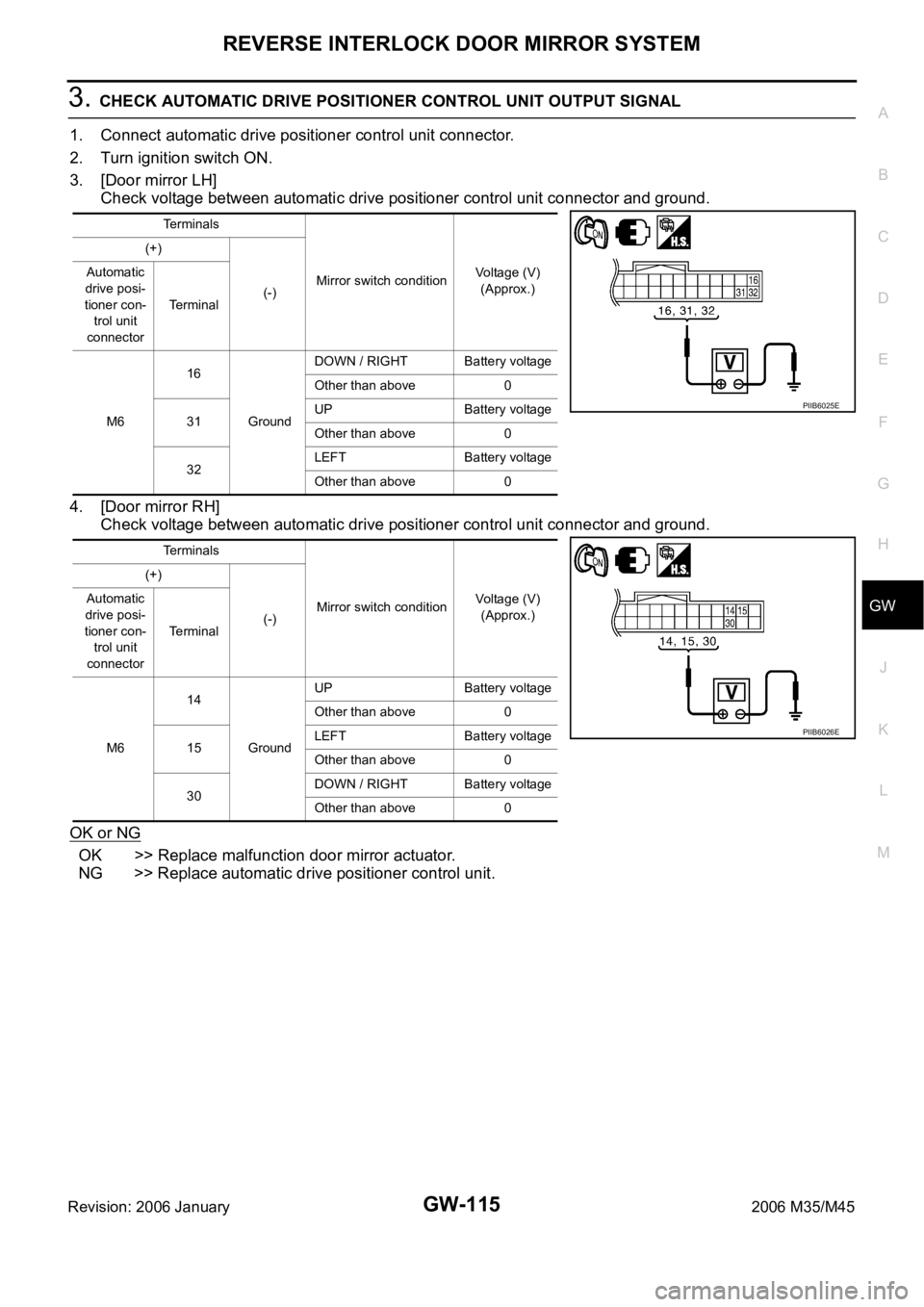
3. CHECK AUTOMATIC DRIVE POSITIONER CONTROL UNIT OUTPUT SIGNAL
1. Connect automatic drive positioner control unit connector.
2. Turn ignition switch ON.
3. [Door mirror LH]
Check voltage between automatic drive positioner control unit connector and ground.
4. [Door mirror RH]
Check voltage between automatic drive positioner control unit connector and ground.
OK or NG
OK >> Replace malfunction door mirror actuator.
NG >> Replace automatic drive positioner control unit.
Terminals
Mirror switch conditionVoltage (V)
(Approx.) (+)
(-) Automatic
drive posi-
tioner con-
trol unit
connectorTerminal
M616
GroundDOWN / RIGHT Battery voltage
Other than above 0
31UP Battery voltage
Other than above 0
32LEFT Battery voltage
Other than above 0
Terminals
Mirror switch conditionVoltage (V)
(Approx.) (+)
(-) Automatic
drive posi-
tioner con-
trol unit
connectorTerminal
M614
GroundUP Battery voltage
Other than above 0
15LEFT Battery voltage
Other than above 0
30DOWN / RIGHT Battery voltage
Other than above 0
PIIB6025E
PIIB6026E