2006 INFINITI M35 turn signal
[x] Cancel search: turn signalPage 4622 of 5621
FRONT FOG LAMP
LT-195
C
D
E
F
G
H
I
J
L
MA
B
LT
Revision: 2006 January2006 M35/M45
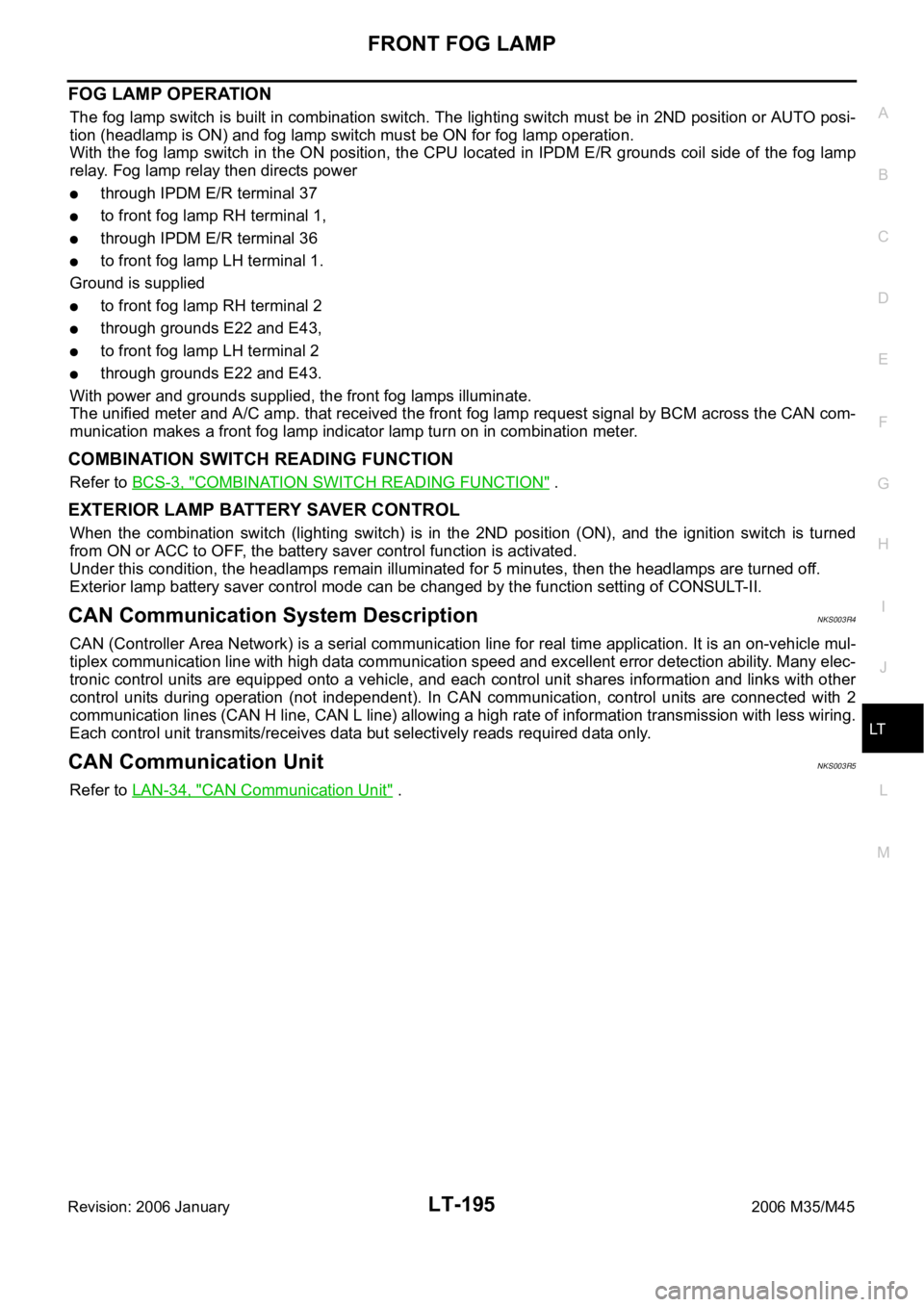
FOG LAMP OPERATION
The fog lamp switch is built in combination switch. The lighting switch must be in 2ND position or AUTO posi-
tion (headlamp is ON) and fog lamp switch must be ON for fog lamp operation.
With the fog lamp switch in the ON position, the CPU located in IPDM E/R grounds coil side of the fog lamp
relay. Fog lamp relay then directs power
through IPDM E/R terminal 37
to front fog lamp RH terminal 1,
through IPDM E/R terminal 36
to front fog lamp LH terminal 1.
Ground is supplied
to front fog lamp RH terminal 2
through grounds E22 and E43,
to front fog lamp LH terminal 2
through grounds E22 and E43.
With power and grounds supplied, the front fog lamps illuminate.
The unified meter and A/C amp. that received the front fog lamp request signal by BCM across the CAN com-
munication makes a front fog lamp indicator lamp turn on in combination meter.
COMBINATION SWITCH READING FUNCTION
Refer to BCS-3, "COMBINATION SWITCH READING FUNCTION" .
EXTERIOR LAMP BATTERY SAVER CONTROL
When the combination switch (lighting switch) is in the 2ND position (ON), and the ignition switch is turned
from ON or ACC to OFF, the battery saver control function is activated.
Under this condition, the headlamps remain illuminated for 5 minutes, then the headlamps are turned off.
Exterior lamp battery saver control mode can be changed by the function setting of CONSULT-II.
CAN Communication System DescriptionNKS003R4
CAN (Controller Area Network) is a serial communication line for real time application. It is an on-vehicle mul-
tiplex communication line with high data communication speed and excellent error detection ability. Many elec-
tronic control units are equipped onto a vehicle, and each control unit shares information and links with other
control units during operation (not independent). In CAN communication, control units are connected with 2
communication lines (CAN H line, CAN L line) allowing a high rate of information transmission with less wiring.
Each control unit transmits/receives data but selectively reads required data only.
CAN Communication UnitNKS003R5
Refer to LAN-34, "CAN Communication Unit" .
Page 4628 of 5621
FRONT FOG LAMP
LT-201
C
D
E
F
G
H
I
J
L
MA
B
LT
Revision: 2006 January2006 M35/M45
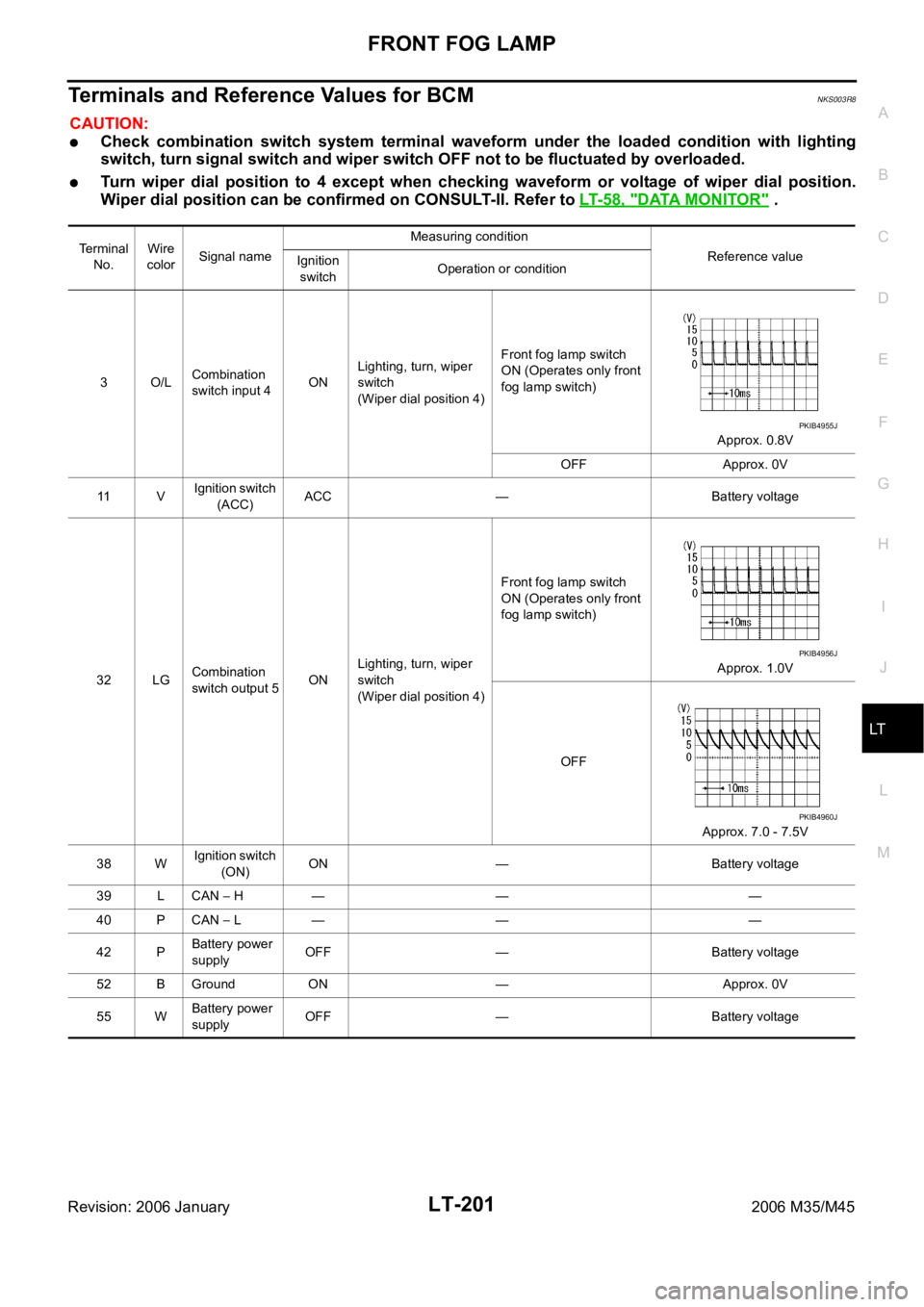
Terminals and Reference Values for BCMNKS003R8
CAUTION:
Check combination switch system terminal waveform under the loaded condition with lighting
switch, turn signal switch and wiper switch OFF not to be fluctuated by overloaded.
Turn wiper dial position to 4 except when checking waveform or voltage of wiper dial position.
Wiper dial position can be confirmed on CONSULT-II. Refer to LT- 5 8 , "
DATA MONITOR" .
Terminal
No.Wire
colorSignal nameMeasuring condition
Reference value
Ignition
switchOperation or condition
3O/LCombination
switch input 4ONLighting, turn, wiper
switch
(Wiper dial position 4)Front fog lamp switch
ON (Operates only front
fog lamp switch)
Approx. 0.8V
OFF Approx. 0V
11 VIgnition switch
(ACC)ACC — Battery voltage
32 LGCombination
switch output 5ONLighting, turn, wiper
switch
(Wiper dial position 4)Front fog lamp switch
ON (Operates only front
fog lamp switch)
Approx. 1.0V
OFF
Approx. 7.0 - 7.5V
38 WIgnition switch
(ON) ON — Battery voltage
39 L CAN
H — — —
40 P CAN
L — — —
42 PBattery power
supplyOFF — Battery voltage
52 B Ground ON — Approx. 0V
55 WBattery power
supplyOFF — Battery voltage
PKIB4955J
PKIB4956J
PKIB4960J
Page 4631 of 5621
LT-204
FRONT FOG LAMP
Revision: 2006 January2006 M35/M45
Front Fog Lamps Do Not Illuminate (Both Sides)NKS003RE
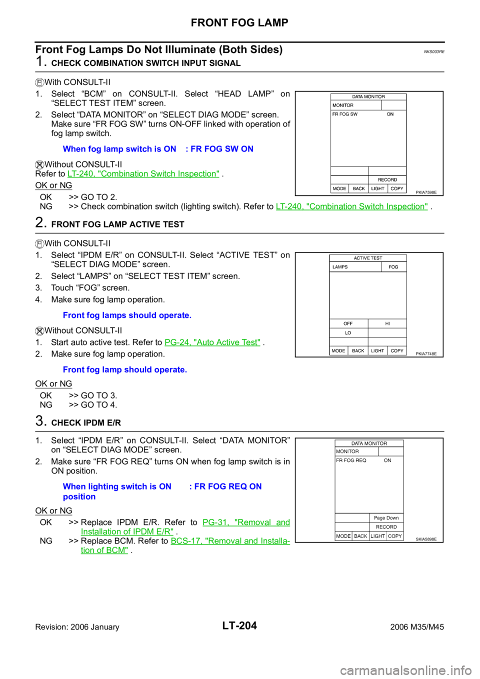
1. CHECK COMBINATION SWITCH INPUT SIGNAL
With CONSULT-II
1. Select “BCM” on CONSULT-II. Select “HEAD LAMP” on
“SELECT TEST ITEM” screen.
2. Select “DATA MONITOR” on “SELECT DIAG MODE” screen.
Make sure “FR FOG SW” turns ON-OFF linked with operation of
fog lamp switch.
Without CONSULT-II
Refer to LT- 2 4 0 , "
Combination Switch Inspection" .
OK or NG
OK >> GO TO 2.
NG >> Check combination switch (lighting switch). Refer to LT-240, "
Combination Switch Inspection" .
2. FRONT FOG LAMP ACTIVE TEST
With CONSULT-II
1. Select “IPDM E/R” on CONSULT-II. Select “ACTIVE TEST” on
“SELECT DIAG MODE” screen.
2. Select “LAMPS” on “SELECT TEST ITEM” screen.
3. Touch “FOG” screen.
4. Make sure fog lamp operation.
Without CONSULT-II
1. Start auto active test. Refer to PG-24, "
Auto Active Test" .
2. Make sure fog lamp operation.
OK or NG
OK >> GO TO 3.
NG >> GO TO 4.
3. CHECK IPDM E/R
1. Select “IPDM E/R” on CONSULT-II. Select “DATA MONITOR”
on “SELECT DIAG MODE” screen.
2. Make sure “FR FOG REQ” turns ON when fog lamp switch is in
ON position.
OK or NG
OK >> Replace IPDM E/R. Refer to PG-31, "Removal and
Installation of IPDM E/R" .
NG >> Replace BCM. Refer to BCS-17, "
Removal and Installa-
tion of BCM" . When fog lamp switch is ON : FR FOG SW ON
PKIA7598E
Front fog lamps should operate.
Front fog lamp should operate.
PKIA7748E
When lighting switch is ON
position: FR FOG REQ ON
SKIA5898E
Page 4632 of 5621
FRONT FOG LAMP
LT-205
C
D
E
F
G
H
I
J
L
MA
B
LT
Revision: 2006 January2006 M35/M45
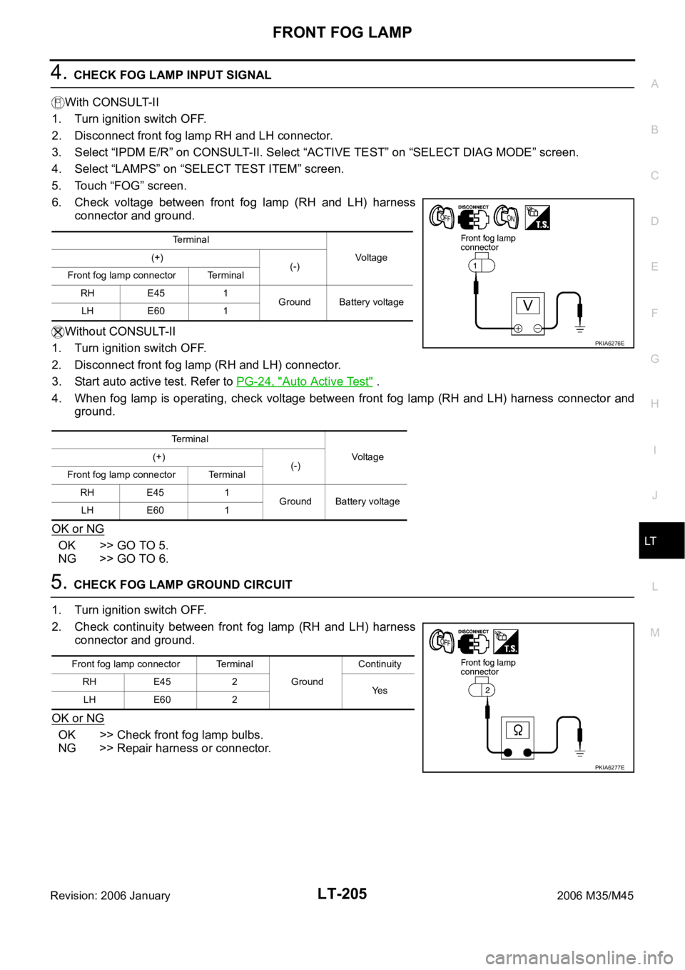
4. CHECK FOG LAMP INPUT SIGNAL
With CONSULT-II
1. Turn ignition switch OFF.
2. Disconnect front fog lamp RH and LH connector.
3. Select “IPDM E/R” on CONSULT-II. Select “ACTIVE TEST” on “SELECT DIAG MODE” screen.
4. Select “LAMPS” on “SELECT TEST ITEM” screen.
5. Touch “FOG” screen.
6. Check voltage between front fog lamp (RH and LH) harness
connector and ground.
Without CONSULT-II
1. Turn ignition switch OFF.
2. Disconnect front fog lamp (RH and LH) connector.
3. Start auto active test. Refer to PG-24, "
Auto Active Test" .
4. When fog lamp is operating, check voltage between front fog lamp (RH and LH) harness connector and
ground.
OK or NG
OK >> GO TO 5.
NG >> GO TO 6.
5. CHECK FOG LAMP GROUND CIRCUIT
1. Turn ignition switch OFF.
2. Check continuity between front fog lamp (RH and LH) harness
connector and ground.
OK or NG
OK >> Check front fog lamp bulbs.
NG >> Repair harness or connector.
Te r m i n a l
Voltage (+)
(-)
Front fog lamp connector Terminal
RH E45 1
Ground Battery voltage
LH E60 1
Te r m i n a l
Voltag e (+)
(-)
Front fog lamp connector Terminal
RH E45 1
Ground Battery voltage
LH E60 1
PKIA6276E
Front fog lamp connector Terminal
GroundContinuity
RH E45 2
Ye s
LH E60 2
PKIA6277E
Page 4634 of 5621
FRONT FOG LAMP
LT-207
C
D
E
F
G
H
I
J
L
MA
B
LT
Revision: 2006 January2006 M35/M45
Front Fog Lamp Does Not Illuminate (One Side)NKS003RF
1. CHECK BULB
Check bulb of fog lamp which does not illuminate.
OK or NG
OK >> GO TO 2.
NG >> Replace front fog lamp bulb.
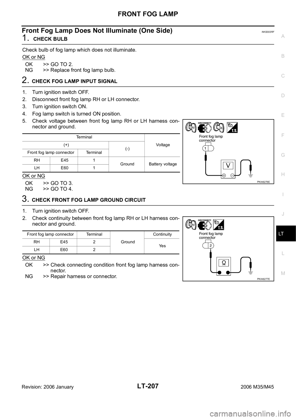
2. CHECK FOG LAMP INPUT SIGNAL
1. Turn ignition switch OFF.
2. Disconnect front fog lamp RH or LH connector.
3. Turn ignition switch ON.
4. Fog lamp switch is turned ON position.
5. Check voltage between front fog lamp RH or LH harness con-
nector and ground.
OK or NG
OK >> GO TO 3.
NG >> GO TO 4.
3. CHECK FRONT FOG LAMP GROUND CIRCUIT
1. Turn ignition switch OFF.
2. Check continuity between front fog lamp RH or LH harness con-
nector and ground.
OK or NG
OK >> Check connecting condition front fog lamp harness con-
nector.
NG >> Repair harness or connector.
Terminal
Voltag e (+)
(-)
Front fog lamp connector Terminal
RH E45 1
Ground Battery voltage
LH E60 1
PKIA6276E
Front fog lamp connector Terminal
Ground Continuity
RH E45 2
Ye s
LH E60 2
PKIA6277E
Page 4635 of 5621
LT-208
FRONT FOG LAMP
Revision: 2006 January2006 M35/M45
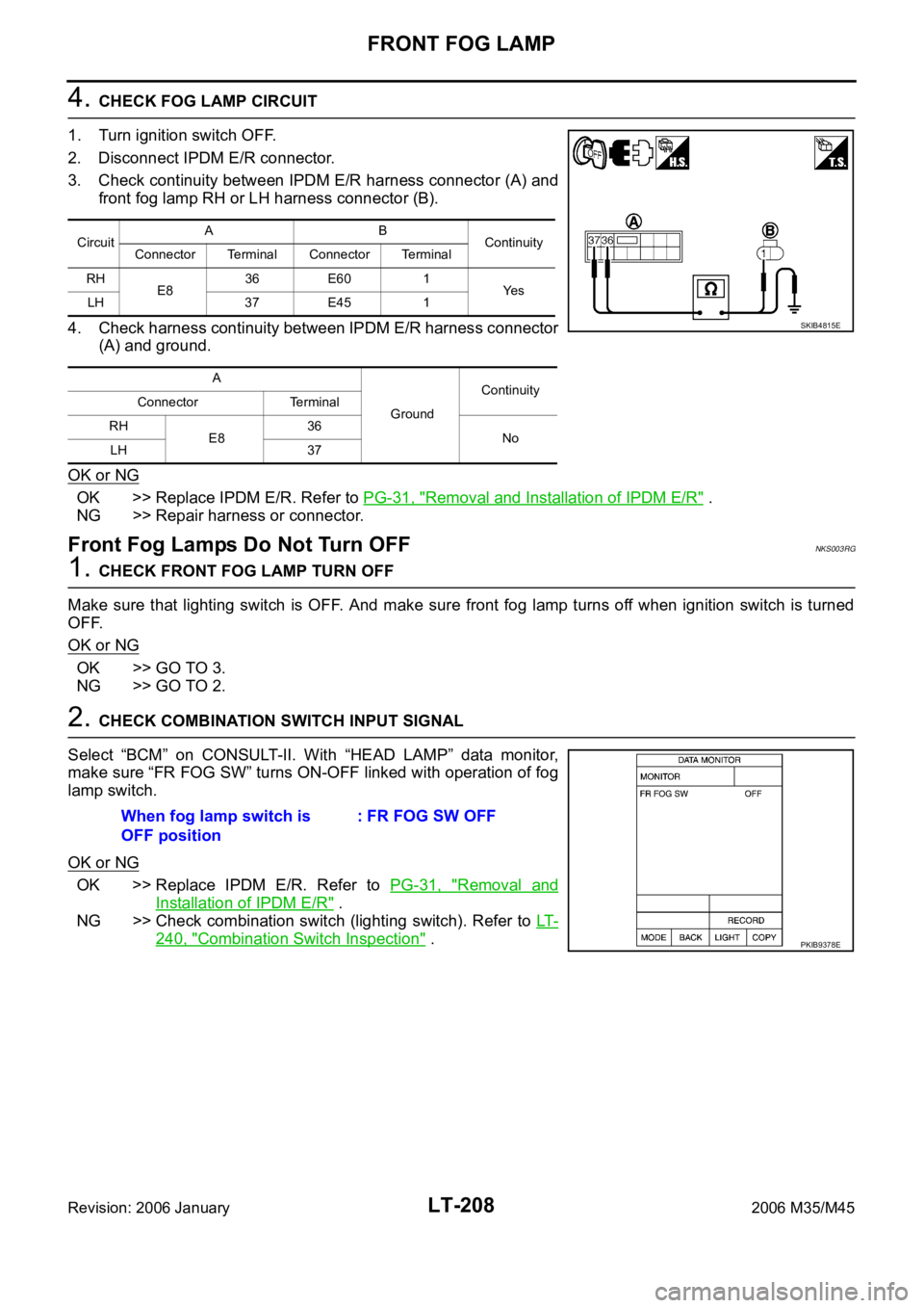
4. CHECK FOG LAMP CIRCUIT
1. Turn ignition switch OFF.
2. Disconnect IPDM E/R connector.
3. Check continuity between IPDM E/R harness connector (A) and
front fog lamp RH or LH harness connector (B).
4. Check harness continuity between IPDM E/R harness connector
(A) and ground.
OK or NG
OK >> Replace IPDM E/R. Refer to PG-31, "Removal and Installation of IPDM E/R" .
NG >> Repair harness or connector.
Front Fog Lamps Do Not Turn OFFNKS003RG
1. CHECK FRONT FOG LAMP TURN OFF
Make sure that lighting switch is OFF. And make sure front fog lamp turns off when ignition switch is turned
OFF.
OK or NG
OK >> GO TO 3.
NG >> GO TO 2.
2. CHECK COMBINATION SWITCH INPUT SIGNAL
Select “BCM” on CONSULT-II. With “HEAD LAMP” data monitor,
make sure “FR FOG SW” turns ON-OFF linked with operation of fog
lamp switch.
OK or NG
OK >> Replace IPDM E/R. Refer to PG-31, "Removal and
Installation of IPDM E/R" .
NG >> Check combination switch (lighting switch). Refer to LT-
240, "Combination Switch Inspection" .
CircuitAB
Continuity
Connector Terminal Connector Terminal
RH
E836 E60 1
Ye s
LH 37 E45 1
A
GroundContinuity
Connector Terminal
RH
E836
No
LH 37
SKIB4815E
When fog lamp switch is
OFF position: FR FOG SW OFF
PKIB9378E
Page 4638 of 5621
TURN SIGNAL AND HAZARD WARNING LAMPS
LT-211
C
D
E
F
G
H
I
J
L
MA
B
LT
Revision: 2006 January2006 M35/M45
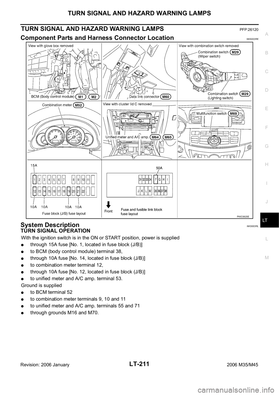
TURN SIGNAL AND HAZARD WARNING LAMPSPFP:26120
Component Parts and Harness Connector LocationNKS003RK
System DescriptionNKS003RL
TURN SIGNAL OPERATION
With the ignition switch is in the ON or START position, power is supplied
through 15A fuse [No. 1, located in fuse block (J/B)]
to BCM (body control module) terminal 38,
through 10A fuse [No. 14, located in fuse block (J/B)]
to combination meter terminal 12,
through 10A fuse [No. 12, located in fuse block (J/B)]
to unified meter and A/C amp. terminal 53.
Ground is supplied
to BCM terminal 52
to combination meter terminals 9, 10 and 11
to unified meter and A/C amp. terminals 55 and 71
through grounds M16 and M70.
PKIC0620E
Page 4639 of 5621

LT-212
TURN SIGNAL AND HAZARD WARNING LAMPS
Revision: 2006 January2006 M35/M45
LH Turn Signal Lamp
When turn signal switch is moved to left position, BCM receives input signal requesting left turn signals to
flash. BCM then supplies power
through BCM terminal 45
to front combination lamp LH (turn signal) terminal 10
to side turn signal lamp LH terminal 1, and
to rear combination lamp LH (turn signal) terminal 3.
Ground is supplied
to front combination lamp LH (turn signal) terminal 9
to side turn signal lamp LH terminal 2
through grounds E22 and E43,
to rear combination lamp LH (turn signal) terminal 4
through grounds B5, B40 and B131.
The BCM also supplies input to unified meter and A/C amp. terminals 56 and 72 across the CAN communica-
tion lines.
The unified meter and A/C amp. which received the turn indicator signal makes the left turn signal indicator
turn on in combination meter.
With power and input supplied, the BCM controls the flashing of the LH turn signal lamps.
RH Turn Signal Lamp
When turn signal switch is moved to right position, BCM receives input signal requesting right turn signals to
flash. BCM then supplies power
through BCM terminal 46
to front combination lamp RH (turn signal) terminal 10
to side turn signal lamp RH terminal 1, and
to rear combination lamp RH (turn signal) terminal 3.
Ground is supplied
to front combination lamp RH (turn signal) terminal 9
to side turn signal lamp RH terminal 2
through grounds E22 and E43,
to rear combination lamp RH (turn signal) terminal 4
through grounds B5, B40 and B131.
The BCM also supplies input to unified meter and A/C amp. terminals 56 and 72 across the CAN communica-
tion lines.
The unified meter and A/C amp. which received the turn indicator signal makes the right turn signal indicator
turn on in combination meter.
With power and input supplied, the BCM controls the flashing of the RH turn signal lamps.
HAZARD LAMP OPERATION
Power is supplied at all times
through 50A fusible link (letter F, located in fuse, fusible link and relay block)
to BCM terminal 55,
through 10A fuse [No. 21, located in fuse block (J/B)]
to BCM terminal 42
to combination meter terminal 23,
through 10A fuse [No. 19, located in fuse block (J/B)]
to unified meter and A/C amp. terminal 54.
When the hazard switch is depressed, ground is supplied
to BCM terminal 29
through multifunction switch terminal 6.
Ground is supplied
to multifunction switch terminal 14